wtw Cond 3300i User manual

ba75684e02 03/2008
Handheld meter
Cond 3300i/3400i
Operating manual
Conductivity measuring instrument
AR
S/
cm
T
ref25
nLF
0
5
2
AR
M
O
30
5
°
C
TP
RCL
STO
CAL

3300i/3400i
2ba75684e02 03/2008
Accuracy when
going to press
The use of advanced technology and the high quality standard of our instru-
ments are the result of continuous development. This may result in differenc-
es between this operating manual and your instrument. Also, we cannot
guarantee that there are absolutely no errors in this manual. Therefore, we
are sure you will understand that we cannot accept any legal claims resulting
from the data, figures or descriptions.
Warranty We guarantee the instrument described for 3 years from the date of pur-
chase.
The instrument warranty covers manufacturing faults that are discovered
within the warranty period. The warranty does not cover components that are
replaced during maintenance work, e.g. batteries.
The warranty claim extends to restoring the instrument to readiness for use
but not, however, to any further claim for damages. Improper handling or un-
authorized opening of the instrument invalidates any warranty claim.
To ascertain the warranty liability, return the instrument and proof of pur-
chase together with the date of purchase freight paid or prepaid.
Copyright ©Weilheim 2008, WTW GmbH
Reproduction in whole - or even in part - is prohibited without the express writ-
ten permission of WTW GmbH, Weilheim.
Printed in Germany.

Cond 3300i/3400i List of contents
3
ba75684e02 03/2008
1 Overview . . . . . . . . . . . . . . . . . . . . . . . . . . . . . . . . . . . . . 5
1.1 SETs of equipment . . . . . . . . . . . . . . . . . . . . . . . . . . . . . . 6
1.2 Keypad . . . . . . . . . . . . . . . . . . . . . . . . . . . . . . . . . . . . . . . 7
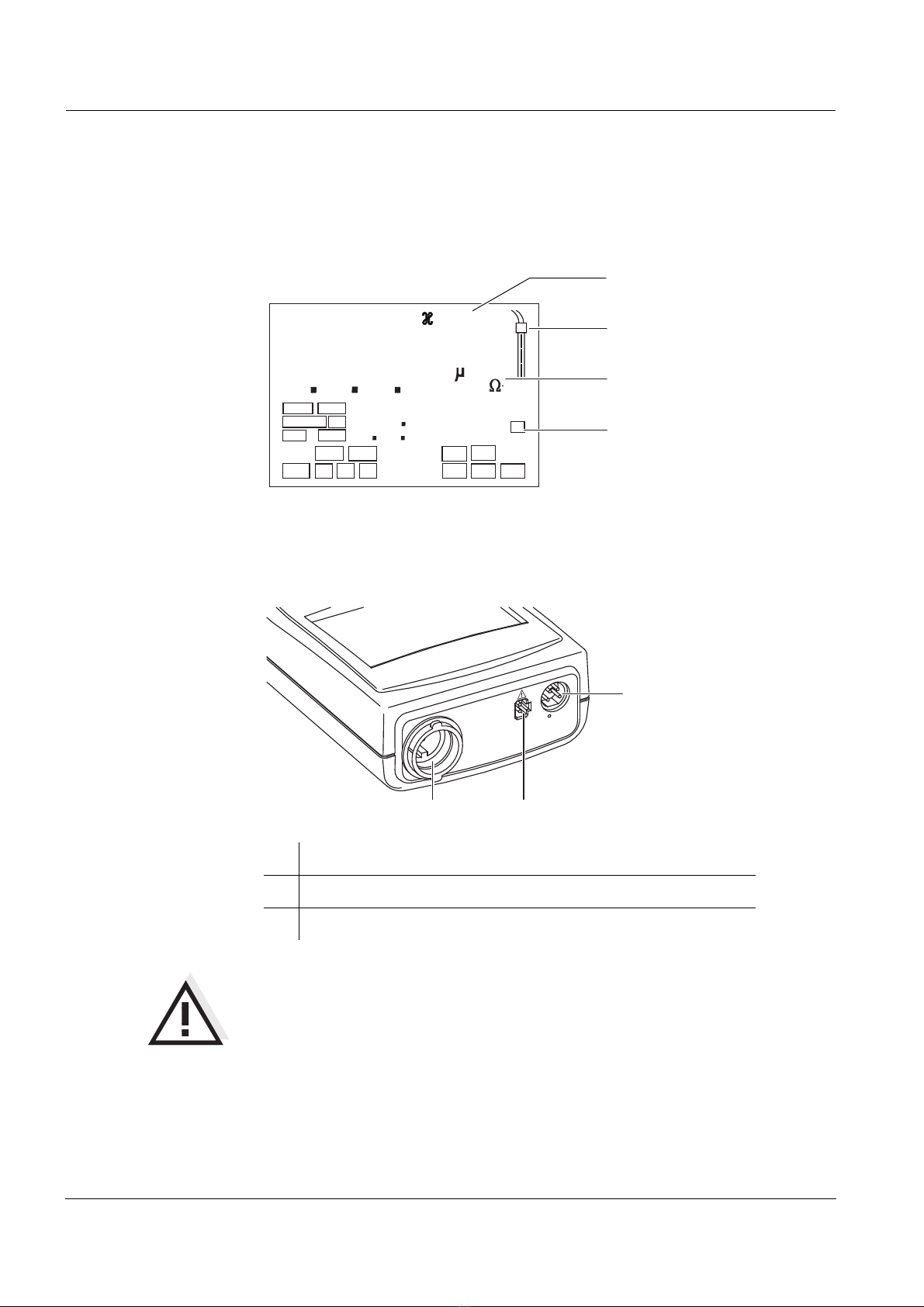
1.3 Display . . . . . . . . . . . . . . . . . . . . . . . . . . . . . . . . . . . . . . . 8
1.4 Jack field . . . . . . . . . . . . . . . . . . . . . . . . . . . . . . . . . . . . . 8
2 Safety . . . . . . . . . . . . . . . . . . . . . . . . . . . . . . . . . . . . . . . . 9
2.1 Authorized use . . . . . . . . . . . . . . . . . . . . . . . . . . . . . . . . . 9
2.2 General safety instructions . . . . . . . . . . . . . . . . . . . . . . . 10
3 Commissioning. . . . . . . . . . . . . . . . . . . . . . . . . . . . . . . 11
3.1 Scope of delivery . . . . . . . . . . . . . . . . . . . . . . . . . . . . . . 11
3.2 Initial commissioning . . . . . . . . . . . . . . . . . . . . . . . . . . . 11
4 Operation. . . . . . . . . . . . . . . . . . . . . . . . . . . . . . . . . . . . 13
4.1 Switching on the measuring instrument . . . . . . . . . . . . . 13
4.2 Measuring . . . . . . . . . . . . . . . . . . . . . . . . . . . . . . . . . . . 14
4.2.1 General information . . . . . . . . . . . . . . . . . . . . . . 14
4.2.2 Conductivity / Specific resistance . . . . . . . . . . . 15
4.2.3 Salinity . . . . . . . . . . . . . . . . . . . . . . . . . . . . . . . . 15
4.2.4 TDS (Total dissolved solids) . . . . . . . . . . . . . . . 16
4.3 Determining/setting up the cell constant [C] . . . . . . . . . . 18
4.3.1 Determining the cell constant (calibrating in the
control standard) . . . . . . . . . . . . . . . . . . . . . . . . 20
4.3.2 Setting the cell constant manually . . . . . . . . . . . 22
4.3.3 Setting the temperature compensation TC . . . . 25
4.4 Saving . . . . . . . . . . . . . . . . . . . . . . . . . . . . . . . . . . . . . . 29
4.4.1 Saving manually . . . . . . . . . . . . . . . . . . . . . . . . 29
4.4.2 Saving automatically . . . . . . . . . . . . . . . . . . . . . 31
4.4.3 Outputting the data storage . . . . . . . . . . . . . . . . 33
4.4.4 Clearing the memory . . . . . . . . . . . . . . . . . . . . . 37
4.5 Transmitting data (only Cond 3400i) . . . . . . . . . . . . . . . 38
4.5.1 Data transmission interval (Int 2, Cond 3400i) . 38
4.5.2 Recorder (analog output, Cond 3400i) . . . . . . . 40
4.5.3 PC/external printer (RS 232 interface, Cond 3400i)
41
4.5.4 Remote control (Cond 3400i) . . . . . . . . . . . . . . 41
4.6 Configuration . . . . . . . . . . . . . . . . . . . . . . . . . . . . . . . . . 42
4.7 Reset . . . . . . . . . . . . . . . . . . . . . . . . . . . . . . . . . . . . . . . 46
5 Maintenance, cleaning, disposal. . . . . . . . . . . . . . . . . 49
5.1 Maintenance . . . . . . . . . . . . . . . . . . . . . . . . . . . . . . . . . . 49
5.2 Cleaning . . . . . . . . . . . . . . . . . . . . . . . . . . . . . . . . . . . . . 50
5.3 Disposal . . . . . . . . . . . . . . . . . . . . . . . . . . . . . . . . . . . . . 50

List of contents Cond 3300i/3400i
4ba75684e02 03/2008
6 What to do if... . . . . . . . . . . . . . . . . . . . . . . . . . . . . . . . . 51
7 Technical data . . . . . . . . . . . . . . . . . . . . . . . . . . . . . . . . 53
8 Lists . . . . . . . . . . . . . . . . . . . . . . . . . . . . . . . . . . . . . . . . 57

Cond 3300i/3400i Overview
5
ba75684e02 03/2008
1 Overview
The compact precision handheld meter Cond 3300i/3400i enables you to car-
ry out conductivity measurements rapidly and reliably.
The Cond 3300i/3400i handheld meter provides the maximum degree of op-
erating comfort, reliability and measuring certainty for all applications.
The proven procedure for adjusting or setting the cell constant and the spe-
cial AutoRead function support you in your work with the conductivity mea-
suring instrument.
Note
If you need further information or application notes, you can obtain the follow-
ing material from WTW:
zApplication reports
zPrimers
zSafety datasheets.
You will find information on available literature in the WTW catalog or via the
Internet.
1Keypad
2Sample display
3Jack field
AR
S/
cm
T
ref25
nLF
0
5
2
AR
M
O
30
5
°
C
TP
R
O
A
1
2
3

Overview Cond 3300i/3400i
6ba75684e02 03/2008
1.1 SETs of equipment
The measuring instrument is also available as part of individual SETs of
equipment. You will find additional information on this and other accessories
in the WTW catalog or via the Internet.
Set (sample configuration):
1 Measuring instrument, Cond 3300i/3400i
2 Stand
3 – 50 ml control standard for conductivity measuring cells
– Beaker, 50 ml
4 Conductivity measuring cell
5 Plug-in power supply, optional (3400i only)
5
4
3
2
1

Cond 3300i/3400i Overview
7
ba75684e02 03/2008
1.2 Keypad
Key functions
RUN/ENTER
ARRCLCAL
STOM
Select the measuring mode <M>:
– Conductivity/Specific resistance
– Salinity
– Total dissolved solids (TDS)
Save a measured value
<STO>
Switch measuring instrument on/off
<ON/OFF>
– Determine or set up the cell constant
– Select temperature compensation
<CAL>
Display/transmit measured values
<RCL>
Activate/deactivate the AutoRead function
<AR>
Increase values, scroll
<▲>
Decrease values, scroll
<▼>
Confirm entries, start AutoRead
<RUN/ENTER>
M
STO
CAL
RCL
AR
RUN/ENTER

Overview Cond 3300i/3400i
8ba75684e02 03/2008
1.3 Display
1.4 Jack field
Warning
Only connect conductivity measuring cells to the measuring instrument that
cannot return any voltages or currents that are not allowed
(> SELV and > current circuit with current limiting).
Nearly all measuring cells - especially WTW measuring cells - fulfill these
conditions.
1TetraCon 325 conductivity measuring cell
2Plug-in power supply (optional) - Cond 3400i only
3Serial interface RS 232 - Cond 3400i only
S
AutoCal DIN
AutoCal TEC
%
mV/pH
Sal
°
F
mbar
OUpH
RCL
8
8.
8
88
8
°
LoBat
Cal
ARng AR
TP
1
m
S/
cm
Sal
cm
1/
C
%/K
Tref25 Tref20
Lin
nLF
Time
Baud
Day.Month No.
Ident
Year
Auto
Store
TDS
mg/l
M
cm
Status display
Meas. value display
Function and
temperature display
Sensor symbol
3
12

Cond 3300i/3400i Safety
9
ba75684e02 03/2008
2Safety
This operating manual contains basic instructions that you must follow during
the commissioning, operation and maintenance of the conductivity measur-
ing instrument. Consequently, all responsible personnel must read this oper-
ating manual before working with the measuring system. The operating
manual must always be available within the vicinity of the measuring system.
Target group The measuring instrument was developed for work in the field and in the lab-
oratory.
We assume that, as a result of their professional training and experience, the
operators will know the necessary safety precautions to take when handling
chemicals.
Safety
instructions
The individual chapters of this operating manual use safety instructions such
as the label shown below to indicate various hazards or dangers:
Warning
indicates instructions that must be followed precisely in order to avoid the
possibility of slight injuries or damage to the instrument or the environment.
Further notes
Note
indicates notes that draw your attention to special features.
Note
indicates cross-references to other documents, e.g. operating manuals.
2.1 Authorized use
The authorized use of the measuring instrument consists exclusively of the
measurement of conductivity, salinity, temperature and TDS (total dissolved
solids) in the field and laboratory.
The technical specifications as given in chapter 7 TECHNICAL DATA must be
observed. Only the operation and running of the measuring instrument ac-
cording to the instructions given in this operating manual is authorized.
Any other use is considered to be unauthorized.

Safety Cond 3300i/3400i
10 ba75684e02 03/2008
2.2 General safety instructions
This instrument is built and inspected according to the relevant guidelines
and norms for electronic measuring instruments (see chapter 7 TECHNICAL
DATA).
It left the factory in a safe and secure technical condition.
Function and
operating safety
The smooth functioning and operational safety of the measuring instrument
can only be guaranteed if the generally applicable safety measures and the
specific safety instructions in this operating manual are followed during oper-
ation.
The smooth functioning and operational safety of the measuring instrument
can only be guaranteed under the environmental conditions that are specified
in chapter 7 TECHNICAL DATA.
If the instrument was transported from a cold environment to a warm environ-
ment, the formation of condensate can lead to the faulty functioning of the in-
strument. In this event, wait until the temperature of the instrument reaches
room temperature before putting the instrument back into operation.
Safe operation If safe operation is no longer possible, the instrument must be taken out of
service and secured against inadvertent operation!
Safe operation is no longer possible if the measuring instrument:
zhas been damaged in transport
zhas been stored under adverse conditions for a lengthy period of time
zis visibly damaged
zno longer operates as described in this manual.
If you are in any doubt, please contact the supplier of the instrument.
Obligations of the
purchaser
The purchaser of the measuring instrument must ensure that the following
laws and guidelines are observed when using dangerous substances:
zEEC directives for protective labor legislation
zNational protective labor legislation
zSafety regulations
zSafety datasheets of the chemical manufacturers.

Cond 3300i/3400i Commissioning
11
ba75684e02 03/2008
3 Commissioning
3.1 Scope of delivery
zHandheld meter, Cond 3300i or 3400i
zPlug-in power supply, optional (3400i only)
zOperating manual and short operating manual
z4 batteries, 1.5 V Mignon type AA (in the instrument)
3.2 Initial commissioning
Perform the following activities:
zSet the date and time
zConnect the plug-in power supply, optional (3400i only)
Setting the date
and time 1Press the <M> key and hold it down.
2 Press the <ON/OFF> key.
The display test appears briefly on the display.
3Press the <RUN/ENTER> key repeatedly until the date appears on
the display.
4 Set the date of the current day with <▲> <▼>.
5Confirm with <RUN/ENTER>.
The date (month) flashes in the display.
6 Set the current month with <▲> <▼>.
7Confirm with <RUN/ENTER>.
The year appears on the display.
8 Set the current year with <▲> <▼>.
9Confirm with <RUN/ENTER>.
The hours flash on the display.
10 Set the current time with <▲> <▼>.
11 Confirm with <RUN/ENTER>.
The minutes flash on the display.
12 Set the current time with <▲> <▼>.
13 Confirm with <RUN/ENTER>.
The instrument switches to the measuring mode.
14 Switch the instrument off using <ON/OFF>.

Commissioning Cond 3300i/3400i
12 ba75684e02 03/2008
Connecting the
plug-in
power supply
(3400i)
You can either operate the measuring instrument with batteries or with the
plug-in power supply. The plug-in power supply supplies the conductivity
measuring instrument 3400i with low voltage (12 V DC). This saves the bat-
teries.
Warning
The line voltage at the operating site must lie within the input voltage range
of the original plug-in power supply (see
chapter 7 TECHNICAL DATA).
Warning
Use original plug-in power supplies only (see
chapter 7 TECHNICAL DATA).
Note
You can also measure without the plug-in power supply.
1Plug the jack (1) into the socket (2) of the measuring instrument.
2 Connect the original WTW plug-in power supply (3) to an easily ac-
cessible mains socket.
2
1
3

Cond 3300i/3400i Operation
13
ba75684e02 03/2008
4 Operation
4.1 Switching on the measuring instrument
Note
The measuring instrument has an energy saving feature to avoid unneces-
sary battery depletion. The energy saving feature switches the measuring in-
strument off if no key has been pressed for an hour. The energy saving
feature is not active when the AutoStore function is active.
Measuring
instrument 3400i
The energy saving feature is also not active
zif the power is supplied by the plug-in power supply,
zif the communication cable and a PC with a running communication pro-
gram are connected,
zif the recorder cable is connected,
zif the printer cable is connected (for external printers).
1Connect a conductivity measuring cell to the measuring instrument.
2 Press the <ON/OFF> key.
The display test appears briefly on the display.
Subsequently, the selected cell constant and the temperature com-
pensation that was set up appear for approx. one second one after
the other.
The measuring instrument then automatically switches to the mea-
suring mode that was last selected.

Operation Cond 3300i/3400i
14 ba75684e02 03/2008
4.2 Measuring
4.2.1 General information
Preparatory
activities
Perform the following preparatory activities when you want to measure:
Warning
When connecting an earthed PC/printer, measurements cannot be per-
formed in earthed media as incorrect values would result. The RS 232 inter-
face is not galvanically isolated.
Temperature
sensor
Only carry out measurements with a temperature sensor. The temperature
sensor is shown on the display by TP.
The WTW TetraCon 325 conductivity measuring cell has a temperature sen-
sor integrated in it.
Note
The conductivity measuring instrument automatically recognizes the type of
the temperature sensor used. This enables to connect measuring cells with
the NTC30 or Pt1000.
Temperature
compensation
The instrument has a nonlinear temperature compensation that can be
switched off (see section 4.3.3 SETTING THE TEMPERATURE COMPENSATION
TC).
Reference
temperature, Tref
The reference temperature (Tref) can be switched between 20 °C and 25 °C.
It appears on the display as Tref20 or Tref25. To switch over the reference
temperature, see section 4.6 CONFIGURATION.
1Connect the conductivity measuring cell to the measuring instrument.
2 In conjunction with the measuring cell, check or calibrate the measur-
ing instument. How to calibrate is described in section 4.3.
3Select the measuring mode with <M>.

Cond 3300i/3400i Operation
15
ba75684e02 03/2008
4.2.2 Conductivity / Specific resistance
Note
You can display measured values in the units μS/cm (conductivity) or MΩcm
(specific resistance). This setting is described in section 4.6 CONFIGURATION.
Thus, you can carry out conductivity measurements or measurements of the
specific resistance:
Conductivity
μS/cm
Specific
resistance MΩ⋅cm
4.2.3 Salinity
You can measure the salinity as follows:
1Perform the preparatory activities according to section 4.2.1.
2 Immerse the conductivity measuring cell in the test sample.
3Press the <M> key until appears on the status display. Depending
on the setting, one of the following display indicators appears on the
display:
AR
8
1
cm
1/
/
K
%
°
F
ARng RCL
Cal
Lin
Tref20
LoBat
M
m
Sal
TDS
S
Auto
Store
Sal
mbar
%
mg/l
OUpH
mV/pH
cm
AutoCal DIN
AutoCal TEC
Time
Baud
Day.Month No.
Ident
Year
0
5
2
30
5
°
TP
S/
cm
C
Tref25
nLF
4Wait for a stable measured value.
1Perform the preparatory activities according to section 4.2.1.
2 Immerse the conductivity measuring cell in the test sample.
m
%
mg/l
S/
cm
S
AR
8
cm
1/
/
K
%
°
F
ARng RCL
Cal
Lin
Tref20
LoBat
Sal
TDS
Auto
Store
Sal
mbar
OUpH
mV/pH
AutoCal DIN
AutoCal TEC
Time
Baud
Day.Month No.
Ident
Year
0
5
2
86
8
°
TP
C
Tref25
nLF
1
M
cm

Operation Cond 3300i/3400i
16 ba75684e02 03/2008
4.2.4 TDS (Total dissolved solids)
You can measure the total dissolved solids as follows:
3Press the <M> key until Sal appears on the status display. The salin-
ity value appears on the display.
4Wait for a stable measured value.
Tref25
/
K
cm
1/
°
F
%
8
mg/l
1
RCL
ARng AR
LoBat
Cal
Tref20
Lin
m
S/
cm
M
TDS
S
Auto
Store
Sal
mbar
%
OUpH
mV/pH
cm
AutoCal DIN
AutoCal TEC
Time
Baud
Day.Month No.
Ident
Year
2
1
2
23
3
°
TP
Sal
C
nLF
1Perform the preparatory activities according to section 4.2.1.
2 Immerse the conductivity measuring cell in the test sample.
3Press the <M> key until TDS appears on the status display.
The value of the total dissolved solids appears in the upper display
line. The TDS factor appears in the lower display line.
4Using <▲> <▼>, set the TDS factor (0.40 ... 1.00).
(The TDS factor has to be determined by a comparison measure-
ment before.)

Cond 3300i/3400i Operation
17
ba75684e02 03/2008
AutoRead AR
(drift control)
The AutoRead function (drift control) checks the stability of the measurement
signal. The stability has a considerable effect on the reproducibility of the
measured value.
Note
The current AutoRead measurement can be terminated at any time (accept-
ing the current value) by pressing <RUN/ENTER>.
5Wait for a stable measured value.
1Select the required measuring mode with <M>.
2 Activate the AutoRead function with <AR>.
The current measured value is frozen (hold function).
3Start AutoRead with <RUN/ENTER>.
AR flashes until a stable measured value is reached.
4If necessary, start the next AutoRead measurement with <RUN/EN-
TER>.
5 To terminate AutoRead: Press the <AR> key.
8
1
cm
1/
/K
%
°
F
ARng RCL
Cal
Lin
Tref20
LoBat
M
m
Sal
TDS
S
Auto
Store
Sal
mbar
%
mg/l
OUpH
mV/pH
cm
AutoCal DIN
AutoCal TEC
Time
Baud
Day.Month No.
Ident
Year
0
5
2
30
5
°
AR
TP
S/cm
C
Tref25
nLF

Operation Cond 3300i/3400i
18 ba75684e02 03/2008
4.3 Determining/setting up the cell constant [C]
Why determine/set
up the cell
constant?
Aging slightly changes the characteristics of the cell, e. g. by coatings. As a
result, an inexact measured value is displayed. The original characteristics of
the cell can often be restored by cleaning the cell. Calibration determines the
current cell constant and stores it in the instrument.
Thus, you should calibrate at regular intervals (we recommend: every 6
months).
Procedure The cell constant is determined in the control standard, 0.01 mol/l KCl.
You can determine the actual cell constant of the conductivity measuring cell
by calibrating with the control standard in the following ranges:
z0.450 ... 0.500 cm-1
(e.g. TetraCon, nominal cell constant 0.475)
z0.800 ... 1.200 cm-1
(cells with a cell constant of approx. 1)
Besides, you can set the cell constant manually in the following ranges:
z0.090 ... 0.110 cm-1
z0.250 ... 2.500 cm-1
The fixed cell constant, 0.010 cm-1 can also be selected. It is not necessary
to calibrate or adjust it.
Cell constants outside the above mentioned ranges cannot be calibrated.
Printing the
calibration
record (3400i)
The calibration protocol contains the calibration data of the current calibration.
You can transmit the calibration protocol to a printer via the serial interface
(see page 36).
Note
You can automatically print a calibration protocol after the calibration. To do
so, connect a printer to the interface according to section 4.5.3 before cali-
brating. After a valid calibration, the record is printed.

Cond 3300i/3400i Operation
19
ba75684e02 03/2008
Sample printout:
Calibration
evaluation
After the calibration, the measuring instrument automatically evaluates the
current status of the calibration. The evaluation appears on the display.
CALIBRATION PROTOCOL
14.04.01 11:37
Device No.: 99990000
Calibration Conductivity
Cal time: 14.04.01 / 11:37
Cal interval: 180d
Cal Std.: 0.01 mol/l KCL
40.0 °C
Conduct./Tref25: 1413µS/cm
Cell Const : 0.478 1/cm
Probe : +++
Display Cell constant [cm-1]
0.450 ... 0.500 cm-1
0.800 ... 1.200 cm-1
E3
Eliminate the error according to
chapter 6 WHAT TO DO IF...
outside the ranges
0.450 ... 0.500 cm-1
or
0.800 ... 1.200 cm-1

Operation Cond 3300i/3400i
20 ba75684e02 03/2008
4.3.1 Determining the cell constant (calibrating in the control
standard)
Note
This method of automatically determining the cell constant by calibration with
the 0.01 mol/l KCL standard solution can only be used for measuring cells
with cell constants in the range 0.450 ... 0.500 cm-1 or 0.800 ... 1.200 cm-1.
This is how you can determine the cell constant:
1Press the <CAL> key until CELL appears on the display.
2Press the <RUN/ENTER> key.
3 Press the <CAL> repeatedly, until the calibrated cell constant ap-
pears on the display: CAL appears on the display.
4The displayed value is the current, calibrated cell constant. You can:
– accept this setting for measuring with <M> or
– continue with step 5 and start a new calibration.
5 Immerse the measuring cell in the control standard solution,
0.01 mol/KCl.
OUpH
LF
Sal
Store
RCL
AR
Auto
AutoCal DIN
AutoCal TEC
LoBat
Cal
ARng
Tref25 Tref20
Lin
nLF
Sal
%
mg/l
mV/pH
cm
°
°
TP
m
S/
cm
cm
1/
FC
%/
K
M
TDS
8
1
S
mbar
Time
Baud
Day.Month No.
Ident
Year
L
CL
E
AL
C
S
1
LoBat
Lin
nLF
Tref20
RCL
ARng AR
°
°
TP
FC
%/
K
M
%
mg/l
mV/pH
m
S/
cm
Sal
TDS
Auto
Store
Sal
mbar
OUpH
cm
AutoCal DIN
AutoCal TEC
Time
Baud
Day.Month No.
Ident
Year
5
07
4
Cal
cm
1/
Tref25
Other manuals for Cond 3300i
1
This manual suits for next models
1
Table of contents
Other wtw Measuring Instrument manuals

wtw
wtw Oxi 330i User manual

wtw
wtw Cond 3310 IDS User manual

wtw
wtw inoLab pH/ION 735 User manual

wtw
wtw Multi 350i User manual

wtw
wtw LF 538 Manual

wtw
wtw Oxi 320 Manual

wtw
wtw Multi 9420 User manual

wtw
wtw photoLab 6100 VIS User manual

wtw
wtw inoLab pH/Oxi Level 1 User manual

wtw
wtw inoLab Oxi Level 2 User manual

wtw
wtw VWR MU 6100 H User manual

wtw
wtw 2F30-100 User manual

wtw
wtw PROTOC 200 User manual

wtw
wtw P 700 IQ User manual

wtw
wtw EcoLine pH 170 User manual

wtw
wtw MULTILINE 1000 User manual

wtw
wtw CR 3000 User manual

wtw
wtw Multi 197i User manual

wtw
wtw IQ SENSOR NET System 2020 XT User manual

wtw
wtw pHotoFlex STD User manual