Wylie MAX-LITE II Programming manual

Express Combo Trailer
Express Water
Distribution Trailer
Express Generator Trailer
Printed In The USA — Specications & Design Subject To Change Without Notice!
4-1-15 14-04R1
Operator’s & Parts Manual

This is a limited warranty. It covers products manufactured by WYLIE Mfg. Co. The Warrantor is WYLIE Mfg. Co., 702 E.
40th St., Lubbock, TX 79404 USA. The duration of the warranty for WYLIE manufactured equipment and products (excluding
polyethylene tanks) is for one year from date of delivery to the carrier. The Warrantor warrants to the Buyer that the product(s)
sold hereunder are free from defects to material and workmanship, under normal use and service, in the hands of the original
buyer.
If goods are defective, the defective goods will be replaced with identical goods. If identical goods are not available, the Buyer
may elect to receive a refund of the purchase price for the defective goods, or the Buyer may order similar goods. The damage
for defective goods shall not exceed the purchase price of the defective goods. No allowance shall be made for labor
or expense or repairing goods without prior approval in writing by the Warrantor. The Buyer’s remedy under this warranty
does not include incidental or consequential damages.
For products not manufactured by the Warrantor, the Warrantor warrants these products to the extent of the warranties of their
respective manufactures. There are no warranties which extend beyond this limited warranty, including the implied
warranty of merchantability. Dealers or representatives shall not make any representation in regard to particular goods except
as authorized by the Warrantor through a written warranty accompanying those particular goods.
WYLIE Mfg. Co., and its divisions, “Wylie Spray Centers,” in each location, requires as a condition of sale and coverage by its
LIMITED WARRANTY that all equipment sold by it be used in accordance with the instructions and specications of the Warrantor.
This requirement is in addition to the LIMITED WARRANTY.
Polyethylene and berglass tanks – These tanks are warranted for the storage and transport of water, herbicide solutions
(on farm), liquid fertilizer and liquid feed. Such tanks should not be used for the storage of any bulk herbicide (undiluted). Any
such use will render this warranty void.
In addition, the Warrantor makes no warranty with regard to bulkhead tank ttings used in connection with tanks containing bulk
herbicides and the use of any such ttings sold by the Warrantor or any WYLIE dealer in connection with tanks containing bulk
herbicides is improper.
Chemical Incompatibility – The Warrantor does not make any recommendations or warranties regarding chemical compatibility.
WYLIE shall not be liable for any damages due to chemical incompatibility, and any Buyer or user should rely solely on written
information furnished by the chemical manufacturer regarding chemical compatibility.
No employee of WYLIE Mfg. Co., or its representatives, agents or dealers, is authorized to vary the terms of this limited
warranty.
This equipment was carefully designed and manufactured to give you dependable service. To insure efcient operation of
this equipment, please read this operator’s manual carefully. Check each item and acquaint yourself with the adjustments
required to maintain optimum performance and operation. Remember, this equipment’s performance depends on
how you operate and care for it!
At the end of each season, thoroughly clean and inspect your equipment. Preventive maintenance saves time and pays
dividends. Your nearest Wylie Spray Center has original equipment parts which assure proper t and best performance.
Record your equipment’s model and serial numbers and the date you purchased this equipment in the space below.
Have this information available when you order parts or attachments.
Model Number:
Serial Number:
Date Purchased:
Limited Warranty
Disclaimer of Warranty
Warranty Information

Wylie Manufacturing Company
702 E. 40th St.
Lubbock, TX 79404
Ph. 888-788-7753
Express Combo Trailer, Water Distribution Trailer,
Generator Trailer
Type of Trailer:
Combo Trailer
Water Distribution Trailer
Generator Trailer
Owner Registration
-- Or Register Online --
Go to: www.wyliesprayers.com
Date of Purchase
Model Number
Tank Serial Number
Trailer Serial Number
Generator Serial Number
Wylie Invoice Number
Owner’s Name
Address
City State Zip
Phone
Email
Dealer
Owner’s Signature
Must be returned within 10 days to validate the warranty.

.

1
Table of Contents
Table Of Contents
Safety Issues ...........................................................................................................................................................2 - 3
Reporting Safety Defects.............................................................................................................................................. 3
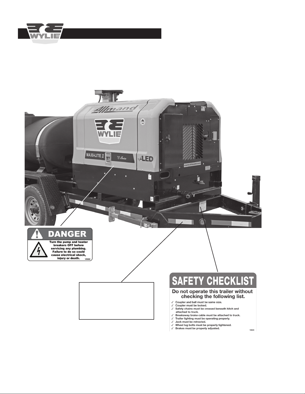
Safety Decals & Placement .....................................................................................................................................4 - 6
Express Combo Trailer
Introduction ................................................................................................................................................................... 7
Inspection & Setup ..................................................................................................................................................8 - 9
Operation ............................................................................................................................................................10 - 16
Lubrication .................................................................................................................................................................. 16
Express Water Distribution Trailer
Introduction ................................................................................................................................................................. 17
Inspection & Setup ..............................................................................................................................................18 - 19
Operation ............................................................................................................................................................20 - 25
Lubrication .................................................................................................................................................................. 25
Express Generator Trailer
Introduction ................................................................................................................................................................. 26
Inspection & Setup ..............................................................................................................................................27 - 28
Operation ............................................................................................................................................................29 - 34
Lubrication .................................................................................................................................................................. 35
Troubleshooting Guidelines ................................................................................................................................. 36 - 38
Tire Safety Information ........................................................................................................................................39 - 49
Notes ...................................................................................................................................................................... 50
Repair Parts .......................................................................................................................................................51 - 70
Express Combo Trailer Parts
Combo Trailer ................................................................................................................................52
Fuel Tank .......................................................................................................................................53
Pump Plumbing .............................................................................................................................54
Tank Plumbing ...............................................................................................................................55
Lights and Brake System...............................................................................................................56
Express Water Distribution Trailer Parts
Water Distribution Trailer ...............................................................................................................57
Pump Plumbing .............................................................................................................................58
Tank Plumbing ...............................................................................................................................59
Freeze Protection Box ...................................................................................................................60
Lights and Brake System...............................................................................................................61
Express Generator Trailer Parts
Generator Trailer ........................................................................................................................... 62
Pump Plumbing .............................................................................................................................63
Tank Plumbing ...............................................................................................................................64
Electrical Connection Box..............................................................................................................65
Fuel Tank .......................................................................................................................................66
Lights and Brake System...............................................................................................................67
All Trailers
Tires & Axles .................................................................................................................................. 68
7,000 lb Axle Assembly.................................................................................................................. 69
Wiring Schematic...........................................................................................................................70

2
Safety Issues
Safety Precautions
Be alert when you see the above symbol in the manual. It warns of a hazard
which might lead to injury. It means: Attention! Become alert! Your safety is
Involved!
Three (3) words (Danger, Warning, and Caution) are associated with this symbol.
DANGER – Indicates a hazardous situation, which, if not avoided, will result in death or serious injury. This signal word
is to be limited to the most extreme situations.
WARNING – Indicates a hazardous situation, which, if not avoided, could result in death or serious injury.
CAUTION – Indicates a hazardous situation, which, if not avoided, may result in minor or moderate injury.
NOTICE – Indicates information considered important, but not hazard-related (e.g., messages relating to property damage).
SAFETY INSTRUCTIONS - Indicates a type of safety sign where specic safety-related instructions or procedures are described.
Before Use
Do not operate trailer until this manual has been read and understood!
• Thoroughly read and understand all instructions before operating this trailer. If you have questions,
please contact Wylie Manufacturing, 702 E. 40th St., Lubbock, TX 79404, (888) 788-7753.
You can also contact your nearest Wylie Spray Center.
• Make sure that the trailer is properly attached to the tow vehicle, including lights, safety chains, hitch and
breakaway brake cable.
•Check lug bolts for tightness and tires for wear.
•Adjust hitch height as needed to assure that trailer is level when fully loaded.
•Read and understand the generator manufacturer owner’s manual for instructions to safely operate the generator
and/or light tower.
During Use
•Do not allow anyone to ride on trailer during transport. Falling can cause injury or death.
•Reduce speed when crossing uneven or rough terrain.
•Always turn off tow vehicle engine before making adjustments or repairs to an attached trailer.

3
Safety Issues
• Inspect trailer for wear or damage.
• Ensure that all fasteners and ttings are tight.
• Drain water from tanks and lines to prevent freezing if unit is not being used.
• Carry out maintenance and/or lubrication procedures as outlined in this manual.
• Keep hands, feet and clothing away from moving parts.
• Hammer grounding rod into the soil when generator is running.
• Assure that the hitch is attached to the proper size ball.
• Attach the safety chains and breakaway brake cable to the tow vehicle.
• Plug the lights into the tow vehicle.
• Be aware that all the components of this non-certied trailer are rated for potable water.
• When possible, avoid operating the tow vehicle near ditches, embankments and holes.
• Reduce speed when turning, crossing slopes and on rough, slick or muddy surfaces.
• Do not permit others to ride.
• Operate tow vehicle smoothly – no jerky turns, starts and stops.
• Hitch only to the hitch points recommended by the tow vehicle manufacturer.
• When tow vehicle is idle, engage brakes and park lock securely.
• Tighten lug bolts before transporting the rst time and maintain proper torque.
• Check lights and wiring daily. Service and replace to maintain proper operation.
• Do not store or transport any petroleum based or ammable liquid in the polyethylene tank.
After Use
Always
Operator’s Instructions
Wylie Manufacturing, 702 E. 40th St., Lubbock, TX 79404
Reporting Safety Defects
If you believe that your vehicle has a defect which could cause a crash or could cause injury or death, you should
immediately inform the National Highway Trafc Safety Administration (NHTSA) in addition to notifying Wylie
Manufacturing.
If NHTSA receives similar complaints, it may open an investigation, and if it nds that a safety defect exists in a
group of vehicles, it may order a recall and remedy campaign. However, NHTSA cannot become involved in indi-
vidual problems between you, your dealer, or Wylie Manufacturing.
To contact NHTSA you may either call the Auto Safey Hotline toll-free at 1-888-327-4236 (TTY: 1-800-424-9153);
go to http://www.safercar.gov; or write to:
NHTSA
U. S. Department of Transportation
12000 New Jersey SE
Washington, DC 20590
You can also obtain other information about motor vehicle safety from the http://www.safercar.gov.

4
Safety Decals & Placement
Safety Issues
Express Combo Trailer
to order safety decal or manual replacements.
Red & White
Reective Tape
Decal #TMP-3M-980-02
Decal #V9029
Decal #V9060
(inside)

5
Safety Issues
to order safety decal or manual replacements.
Red & White
Reective Tape
Decal #TMP-3M-980-02
Decal #V9029
Safety Decals & Placement
Express Water Distribution Trailer
Decal #V9060

6
Safety Issues
to order safety decal or manual replacements.
Red & White
Reective Tape
Decal #TMP-3M-980-02
Decal #V9029
Safety Decals & Placement
Express Generator Trailer
Decal #V9060

7
The Wylie Express Combo Trailers are the result of years of testing and eld proven experience. They are built of the
nest materials and expert workmanship to provide you with years of reliable service. The Express Combo Trailer is
equipped with a 500 gallon polyethylene tank, a pressurized water distribution system, and a 13.5 kW Allmand generator
with 25’ LED light tower. An optional factory installed freeze protection kit is available. The Express Combo Trailer is a
DOT approved trailer that come standard with lights, surge brakes and heavy duty walkway fenders.
The Wylie Express Combo Trailers are designed to supply water, power and light to RV’s and mobile ofces at oil eld
or construction sites.
This manual explains how to safely and properly operate and maintain your Express Combo Trailer. A separate manual
is included with operating instructions for the Allmand generator. Thoroughly read and understand the contents of this
manual before operating your trailer. If you have questions or do not understand particular items, contact your nearest
Wylie Spray Center or call Wylie Manufacturing at (888) 788-7753. Please keep this manual handy to answer questions
you may have as they arise.
Pay Particular Attention To All Safety Suggestions – Their purpose is to assure safe operation of the trailer and
prevent injury or damage to yourself or the unit.
Combo Introduction
Introduction
500 Gal. Express Combo Trailer

8
Combo Inspection & Setup
Inspection & Setup - Express Combo Trailer
Express Combo Trailer
Your Express Combo Trailer is delivered ready for op-
eration. However, it is suggested that you check lug nuts
and other fasteners for proper torque. Check the motor
to assure that it has the proper oil level (see the motor
operator’s manual for details). Make a visual inspection
to assure that nothing was damaged in shipping. Report
any problems to your dealer or to Wylie Manufacturing.
The owner’s manual should be stored in the manual stor-
age sleeve located inside the engine compartment.
Attaching Trailer To Truck
The Wylie Express Combo trailer requires a 2 5/16” ball.
Make sure that the ball and hitch are the same size.
Remove the lock pin from the hitch and slide the lock
collar back until the hitch opens. Lower the hitch onto
the ball. Close the hitch. The spring loaded lock collar
will slide forward into place. Insert and fasten the lock
pin in place.
Attach the safety chains to the eyelets. DOT regulations
require that the safety chains cross as they are at-
tached.
The surge brake system is equipped with an emergency
cable that activates the brake system if the trailer becomes
unhitched during transport. The emergency cable should
be clipped to the tow vehicle.
Plug the light cable into the truck light socket. Check the
lights to make sure that the clearance, turn, brake and tail
lights are working properly.
The Combo Trailer is equipped with a drop-leg jack. Once
the trailer is attached to the truck, rotate the jack handle
to raise the jack pad to the highest point. Remove the lock
pin and raise the drop-leg to the highest setting and insert
the lock pin. (See Fig. A4)
Figure A1
Manual Storage Sleeve
The ball and hitch must be the same size. Attaching
a 2 5/16” hitch to a 2” ball could allow the
trailer to become unhitched during transport.
Serious bodily injury could follow. Figure A3
Connections to Truck
Manual Storage >
Sleeve
Figure A2
Hitch in Open Position
The Combo Trailer should be pulled by a ¾ ton or
larger truck. Pulling with a smaller truck could cause
loss of control and serious injury or death.
< Lock Collar
< Lock Pin
Crossed >
Safety
Chains
< Emergency
Brake Cable
< Electric Cable
Open Hitch >

9
Fill the fuel tank with low sulphur diesel through the ll cap
on the right front corner of the tank.
Setting the Ground Rod
See the Allmand generator owner’s manual for more de-
tailed instructions. The ground rod is stored in the engine
compartment.
1. Drive the ground rod (provided) fully into the ground
using a heavy hammer, such as a single jack.
2. Attach the grounding cable (provided) to the rod and
then to the grounding lug on the trailer. Make sure that
the cable connections are tight.
Figure A5
Adjust Hitch Height for Level Trailer
The Wylie Express Combo trailer is equipped with a height
adjustable hitch. The trailer should travel level when the
tank is full. To level the hitch, lower the jack to support the
tongue, remove the hitch bolts, adjust the tongue height
as needed, and reinsert the hitch bolts.
Setting Up Trailer for Operation
Position the trailer in a relatively level area. Lower and set
the jack drop-leg, then rotate the handle to raise the trailer
and unhook from the towing vehicle.
Rotate the outrigger jacks. Extend the jacks so that the
trailer is level or lowered by ½” on the hitch end (for full
fuel usage in the fuel tank).
Figure A6
Set Outrigger Jacks to Stabilize Trailer
Figure A7
Diesel Tank Fill Cap
< Drop-Leg Jack
< Lock Pin
Figure A4
Drop-Leg Jack Operation
< Height Adjustable
Hitch
< Outrigger Jacks
Outrigger Jacks >
Diesel Tank Fill Cap >
Figure A8
Set and Connected Ground Rod
Ground Rod >
< Grounding Lug
< Drop Leg
Inspection & Setup - Express Combo Trailer, cont’d.
Combo Inspection & Setup

10
Operation - Express Combo Trailer
The Express Combo trailer is designed to provide water,
power and light to portable ofces, RV’s, or work trailers
at temporary job sites. All the uid components of this
non-certied trailer are rated for potable water.
Filling the Water Tank
The 500 gallon water tank can be lled through the llwell
or the quick-ll tting. To ll through the llwell, remove
the tank lid by rotating counterclockwise and insert the
customer supplied ll hose. Make sure the hose is clean
and free of any foreign matter. The hose end should stay
above the water level.
The water tank is equipped with a “bottom load” three
way valve. This valve allows ow to either PUMP or FILL/
DRAIN with a center OFF position which closes the valve.
The valve and hose may be wrapped with freeze protec-
tion insulation and heat cord. See more information on this
system on page 13.
To ll the tank through the quick-ll valve, place tank valve
to OFF position before removing quick-ll cap. Remove
quick-ll Cap, attach the ll line 2” coupler and move valve
to FILL-DRAIN position for lling.
If the tank is being lled from a municipal water supply,
it is recommended that an optional anti-siphon ll kit
(W1440FILL) be mounted on the fender.
When tank is full, rotate 3-way valve to the OFF position
before disconnecting the ll hose from the quick-ll valve.
Replace the cap. Rotate the 3-way valve to the PUMP
position.
Connection to the Water System
The water pump and pressure tank are located in the en-
gine compartment. If the trailer is equipped with the freeze
protection kit, the water pump and pressure tank are inside
an insulated metal box. Unscrew the wing nuts and remove
the top of the box. In warm weather the top should be re-
moved for pump cooling. The top can be stowed between
the insulated box and the engine compartment cover.
Combo Operation
Figure A9
Filling Tank Through Fillwell
Figure A10
Filling Tank Through Quick-Fill Fitting
Figure A12
3-Way Valve in PUMP Position
Fill Hose >
Valve in FILL >
Position
< Fill Hose
Valve in PUMP >
Position
Figure A11
Optional Anti-Siphon Fill
< Anti-Siphon Fill
< Fill Hose From Municipal Supply
Quick-Fill Cap >
< 2” Quick-Fill Coupler

11
Combo Operation
Route the distribution hoses through the slot on the front of
the generator housing and through the insulated holes (if
equipped) in the front of the pump box. Connect distribu-
tion hose ttings to the two output hoses from the pump.
The distribution hoses may need freeze protection which
is not included in the freeze protection kit.
Water System Electrical Connections
The Allmand Generator Operator’s Manual should be read
and understood.
The Wylie Express Combo trailer has additional circuits
specic to the water supply and freeze protection system.
There are two dual GFCI outlet boxes mounted above the
pump box in the generator cabinet. They are protected by
two circuit breakers, one for each of the dual outlets. The
2 dual outlets provide power for the water pump (1½ Amps),
two heat cords (3 Amps total) and the tank heater (12½
Amps). These circuit breakers are protected by the Main
Circuit breaker (90 Amps) in the front generator control panel.
This main circuit breaker on the front generator
console should be turned OFF before shutting down
the diesel engine/generator. Failure to turn off this
circuit breaker (and the lights) can damage the
generator circuit and is not covered by warranty.
Water System Operation
With Water Tank valve positioned to PUMP and the two
hose bibs in the pump box turned off, plug in the water
pump cord to one of the free outlets in the dual GFCI out-
let box above the pump box inside the generator cabinet.
(Do not use either of the dual outlets on the plug-in “Ther-
moCube” socket receptacle which is solely used for the
freeze protection circuits). There is no “Off/On” switch, the
water system uses a demand pump that cycles on and off
according to water pressure; ON at 25 psi, OFF at 45 psi.
The generator must be running to provide power to the wa-
ter pump. Refer to the Allmand generator owner’s manual
for operating instructions of the generator.
Figure A13
Distribution Hose Connection
Figure A14
Electrical Connections
Figure A15
Pump Electrical Connections
< Distribution Hose
< Insulated Box Top
< GFCI Outlet Box
Breaker Box >
Hose Bib >
Pump Plug >
< ThermoCube
< GFCI Outlet
DANGER
Turn the pump and heater breakers OFF or unplug
the pump and heaters before servicing any
plumbing. Failure to do so could cause
electrical shock, injury or death.
Operation - Express Combo Trailer, cont’d.

12
Possible Problems
1. If the pump is not operating, the system may be pressur-
ized and the pump’s internal pressure switch is activated.
The pump will resume operation when sufcient water is
drawn from the system to lower the pressure in the tank.
2. The electrical GFCI outlet into which the pump is plugged
can trip. Push the button in the middle of the outlet to reset.
3. There are also two circuit breakers which protect the
two electrical outlets which may need to be reset. These
circuit breakers are located on the back of the main panel
in the engine compartment.
4. If the pump is mistakenly plugged into the ThermoCube
(see below), the internal thermostat will shut off the outlets
in temperatures above 45°F. The pump should only be
plugged into the GFCI electrical outlets.
5. There is a line strainer in the garden hose adapter just
upstream of the pump. If the lter is clogged, ow will
be diminished or shut off completely. Turn the main tank
valve off and unplug the pump before loosening this garden
hose adapter.
Combo Operation
The water supply system includes a pressure tank which
provides steady water ow and reduced pump cycling.
The tank is pressurized (air) at the factory to 25 psi. The
pressure can be checked in the eld using a standard tire
pressure gauge. A protective cap covers the air valve on
the rear of the pressure tank. Check the air pressure when
the tank is empty.
With the pump running, open the gate valves on the output
hose bibs. Allow several minutes for the tank to ll and to
purge air from the distribution hoses.
Figure A18
Line Strainer
The ThermoCube is a thermostatically controlled
electrical outlet. Only the heat cords should be
plugged into the ThermoCube.
Figure A16
Pressure Tank Air Valve
Air Valve >
Figure A17
Water Pump Connections
Distribution Hose >
Gate Valve >
< Line Strainer
< Supply Line
Gate Valve >
Operation - Express Combo Trailer, cont’d.

13
Tank Heater:
There is a 110 VAC, 1500 W, thermostatically controlled
tank heater mounted in the water tank. The internal ther-
mostat turns on at 38° F and off at 45° F. The tank heater
power cord reaches from the tank forward into the genera-
tor cabinet and should be plugged into one of the spare
outlets in the dual GFCI outlet above the pump box. It
should not be plugged into the ThermoCube.
This heater is mounted in one of the tank bulkheads slightly
above and to the side of the main tank water valve. In cold
weather the water level should not be allowed to fall below
the height of the tank heater.
The tank heater cord should be unplugged in non-freezing
weather.
Supply Line Insulation:
Foam wrap tubing and foam tees surround the supply line,
3-way valve and heat cord. These connections should
remain intact unless necessary for repairs, etc. Care
must be taken when reassembling that the cord and foam
components are placed in their original locations to assure
proper freeze protection.
Optional Freeze Protection System
Your Express Combo Trailer may have been equipped with
an optional factory installed freeze protection system. This
system utilizes a variety of components to protect the water
system on the Express Combo Trailer.
Heat Cords:
There are two heat cords that protect the pump supply
line and the water tank and components in the pump box.
These two heat cords should plug into the ThermoCube
which in turn plugs into the GFCI electrical receptacle
inside the engine compartment. The ThermoCube has a
thermostatically controlled switch which turns on at 35°F
and goes off at 45°F. One heat cord wraps around the
supply line while the other wraps around the pressure tank
components. They are internally self-regulating and will
supply heat according to the temperature in the compo-
nents they protect. In warmer weather, these heat cords
should be unplugged.
These heat cords conduct 110 VAC and should be handled
with caution. They are shielded with an external, braided
wire which acts as a physical shield and are also safety
grounded. Should the heat cord be cut or damaged, the
cord should be unplugged from the ThermoCube and re-
placed. Call the factory for replacement parts.
Combo Operation
Figure A19
Heat Cord Connections
Figure A20
Outside Tank Heater Inside
Figure A21
Foam Insulation
Pump Plug >
< ThermoCube
< GFCI Outlet
< Tank Heater Plug
Heat Cord Plug >
Heat Cord Plug >
< Foam Tee
Foam Insulation >
Heater cords carry 110 VAC. Unplug cords if cut
or damaged. Failure to do so could cause
electrical shock and injury.
Foam Tee >
Operation - Express Combo Trailer, cont’d.

14
2. Remove the drain hose and open the gate valves
to drain any remaining water into the pump box.
3. With the pump supply hose disconnected at the
swivel, remove the poly plug and brass cap from the tank
plumbing as shown in Figures A23 and A24. The water in
the supply line will gravity ow out of the line.
4. Reconnect the supply line and install the cap
and plug to prevent any foreign matter from getting in the
line.
Combo Operation
Water System Drainage:
The supply line leading from the water tank to the pump
is heated in cold weather when the generator is running.
During transport or periods of inactivity, it may need to be
protected. Running the generator during transport is a
simple method of protecting the tank and supply lines. If
the generator is not available or if the unit will not operate
for an extended period, the water tank, supply line, pump/
pressure tank and hose bib components need to be drained.
There are two generations of plumbing on the Express
Combo Trailer i.e. before Serial Number 051695 and after
Serial Number 051695 (inclusive). Draining the tank is
universal across all trailers. Draining the supply line to the
pump is specic to the particular generation of plumbing.
Tank Drainage: Turn the valve to OFF. Remove the
quick-couple cap and connect a drain line to the quick-
couple tting at the main tank valve. Turn the valve to
DRAIN and empty the tank. Disconnect the drain hose and
reattach the quick-couple cap. Turn the valve back to OFF.
Pump System Drainage on Combo Trailers
above Serial Number 051695 (inclusive)
1. With the main tank valve turned to OFF, discon-
nect the supply hose from the pump inlet. Connect a drain
hose to a pressure tank hose bib and release the pressur-
ized water which will empty the pressure tank. In addition,
run the pump until it runs dry. Unplug the pump.
Figure A22
Draining Tank
Valve in DRAIN >
Position
< Drain Hose
Quick-Fill Cap >
Figure A24
Draining Supply Hose on Units Above
Serial Number 051695
< Valve in OFF
Position
Poly Plug >
< Clamp
Drain Hose >
Gate Valve >
< Pump Inlet
< Hose Bib
< Supply Line
Gate Valve >
Figure A23
Draining Pressure Tank and Hoses on Units Above
Serial Number 051695
< Brass Cap
Box Lid >
Operation - Express Combo Trailer, cont’d.

15
Trailer Operation
Towing a loaded trailer requires added care and concentra-
tion for safe operation.
(1) Loaded trailers require a longer stopping distance.
Maintain an increased following distance.
(2) Trailers turn a shorter radius than the tow vehicle.
Swing wide on turns to prevent colliding with other vehicles
or structures.
(3) Loaded trailers require more time to attain highway
speeds. Take extra care when merging with trafc.
(4) Make sure that the tow vehicle is sized to properly
tow the trailer at maximum load. The hitch must also be
rated to handle the maximum trailer load.
(5) Make sure that the tow vehicle is properly equipped
to safely tow the trailer. The tow vehicle should be equipped
with functional light and brake equipment, safety chain
anchors, and correctly sized and anchored ball.
(6) Check the following components regularly:
Tires: Check and maintain proper ination daily.
Lights: Inspect lights, wiring and plug daily. Replace dam-
aged or worn components.
Brake system: Check uid level in brake actuator.
Hitch: Before each trip, make sure that the hitch is properly
locked on the ball. Replace the hitch if it becomes worn
or inoperable.
(7) The trailer is equipped with a step, handholds and
slip resistant treads to allow access to the light tower mast.
Combo Operation
Add only non-toxic RV Antifreeze to the system.
Adding toxic automotive antifreeze will cause
sickness and death.
Additional Freeze Protection:
If the Combo Trailer needs freeze protection for an extend-
ed period, the system can be protected with RV antifreeze.
Drain the tank as described above, add enough RV an-
tifreeze to ll the system. Open outlets at the pump and
allow the pump to run long enough to ll the system with
RV antifreeze.
When the Combo Trailer is to be used again, thoroughly
ush the system with clean water, then drain before rell-
ing tank with water.
Additional Information:
The box lid should be secured on the box in cold weather
to retain heat inside the box. During warm weather, remove
the lid to keep the pump of overheating. The lid can be
stowed between the box and the generator cabinet.
Diesel Tank
The diesel tank is a rectangular steel tank located beneath
the 500 gallon water tank. The diesel tank supplies fuel to
the generator engine. An un-level trailer can substantially
affect the amount of fuel available to the engine.
The trailer should be level or 1/2” lower in the front to
maximize fuel availability.
Any trash or foreign matter in the fuel will accumulate in the
fuel line lter at the engine. The lter should be replaced
when necessary.
The tank can be drained by opening the drain plug located
at the right rear corner of the tank bottom. Always be care-
ful when draining the tank to retain the fuel collected for
proper disposal.
Use only low sulphur diesel fuel as specied by Allmand
generator owner’s manual.
Operation - Express Combo Trailer, cont’d.
Figure A25
Diesel Tank
< Diesel Tank

16
Chemical Compatibility
The polyethylene tank is designed to hold water. Wylie
polyethylene tanks are not designed to hold petroleum
based chemicals or petroleum fuels.
The steel fuel tank should only be lled with low sulphur
diesel.
Other Operations
All set-up, operating and maintenance instructions for
the generator and light tower are included in the Allmand
Generator Operator’s Manual.
Figure A26
Accessing Light Tower
< Handhold
< Handhold
Step >
Lubrication
The wheel bearings should be serviced every 6 months
or every 6,000 miles (whichever comes rst). Lubrication
may be needed more often if the trailer is used in severe
conditions. The wheel hubs should be checked regularly for
excess heat. Heat buildup is an indication that the bearings
need grease and may soon fail.
The axles are equipped with Accu-Lube hubs. Remove
the rubber boot and attach grease gun to the grease zert.
Replace the rubber boot after the hub is serviced.
Combo Operation
Operation - Express Combo Trailer, cont’d.
Figure A27
Accu-Lube Hub
Rubber Boot >
< Grease Zert
Table of contents
Other Wylie Farm Equipment manuals
Popular Farm Equipment manuals by other brands

Checchi & Magli
Checchi & Magli UNITRIUM owner's manual

Grouser Products
Grouser Products 770HD Steiger T4B Wheeled Owner's manual & parts book

Trebro
Trebro Quadlift QL016 Owner's/operator's manual

SKY Agriculture
SKY Agriculture Easy Drill W Series Original instructions

HARVEST
HARVEST T1036 Operator's manual

Seppi
Seppi MIDIPIERRE Operating and maintenance manual