
www.xa.com 9
Quick start guide
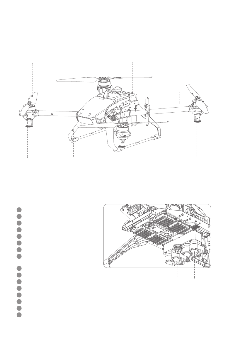
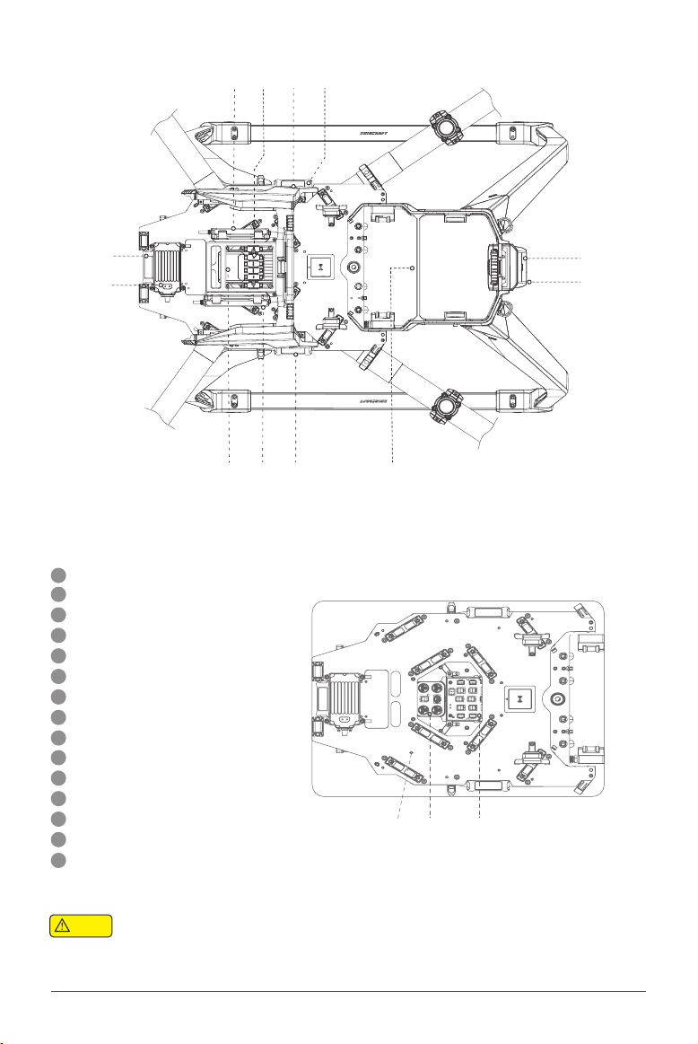
Arms installation
5. Dismantle the fixed
sliders of No.1 and No.2 arm
Dismantle the screws (4 screws on 2
sliders) on limiting stopper of No.2 arm top
sliders; and, then pull out the sliders.
6. Install No.1 and No.2 arm
Insert the No.2 short arm from designated
position of airframe plate, and then install
the top slider back to its original position to
complete assembling of No.2 arm. (The removal/
installation of No.1 arm is the same as that of
No.2 arm)
SliderBuckle
Dismantle the screws (4 screws on 2 sliders)
on limiting stopper of No.3 arm top sliders;
and, then pull out the sliders and Dismantle
the carbon framed fasteners (2 screws on 1
fastener) of side arms.
7. Dismantle the fixed slider
of No.3 and No.4 arm
8. Install No.3 and No.4 arm
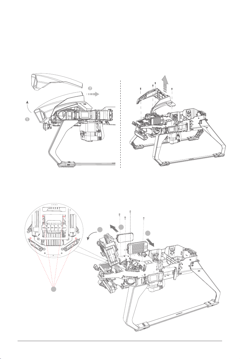
Insert RTK feeder and 2.4/5.8GHz feeder into
the No.3 short arm first, insert the arm from
designated position of the airframe, and then
install top slider and arm fasteners back to their
original position to complete the assembling of
No.3 arm. (The removal/installation of No.3 arm
is the same as that of No.4 arm)
馈线
Feeder


 user manual")


