SHOCKS
Shocks, or shock absorbers, are
a part of the suspension that
allow the wheels to keep as
much contact with the running
surface as possible. Damping,
mounting position, spring
tension, and spring preload
are all characteristics that
determine how the shock
performs.
SShhoocckk sseettttiinnggss::
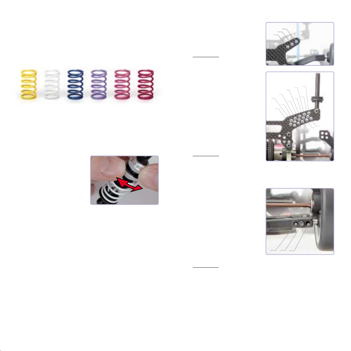
The T EVO2 features unique 4-step externally adjustable racing shocks that
do not require you to change pistons or change the oil to alter the damping.
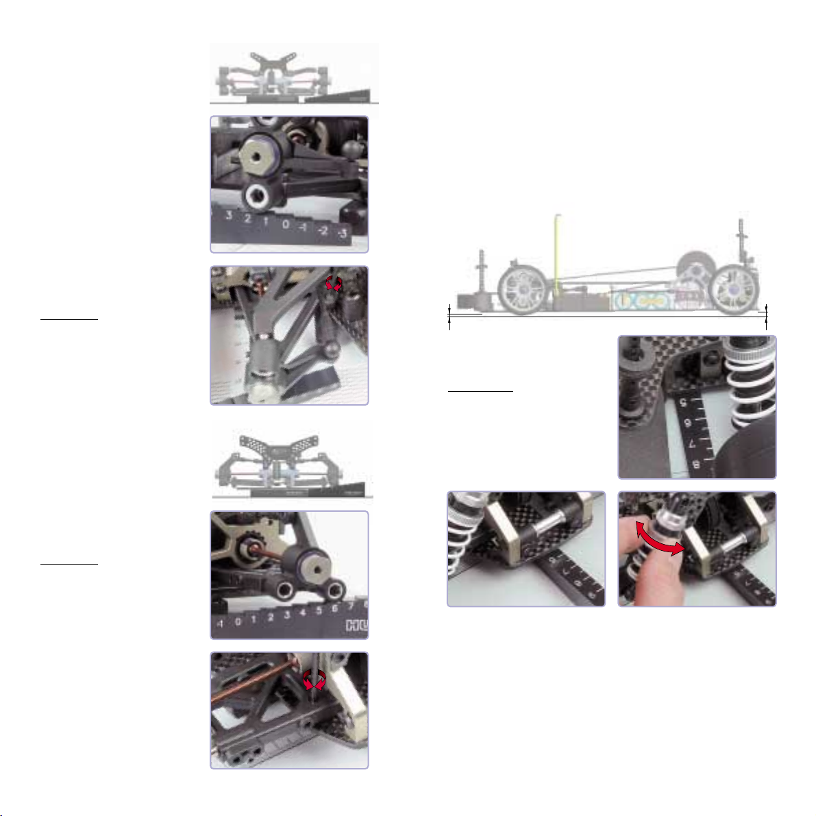
Initially, the damping should be set separately for the front and the rear so
that the car quickly settles when dropped from approximately 5 cm (2"). For
our initial settings, if it bounces before settling, it is too stiff. If it slaps the
table, it is too soft.
•• SSoofftt ddaammppiinnggwill produce most grip (both front and rear) through chassis
roll, but this will also decrease the cornering speed.
•• HHaarrdd ddaammppiinnggwill make the car break traction more easil , but with less
chassis roll and higher cornering speed.
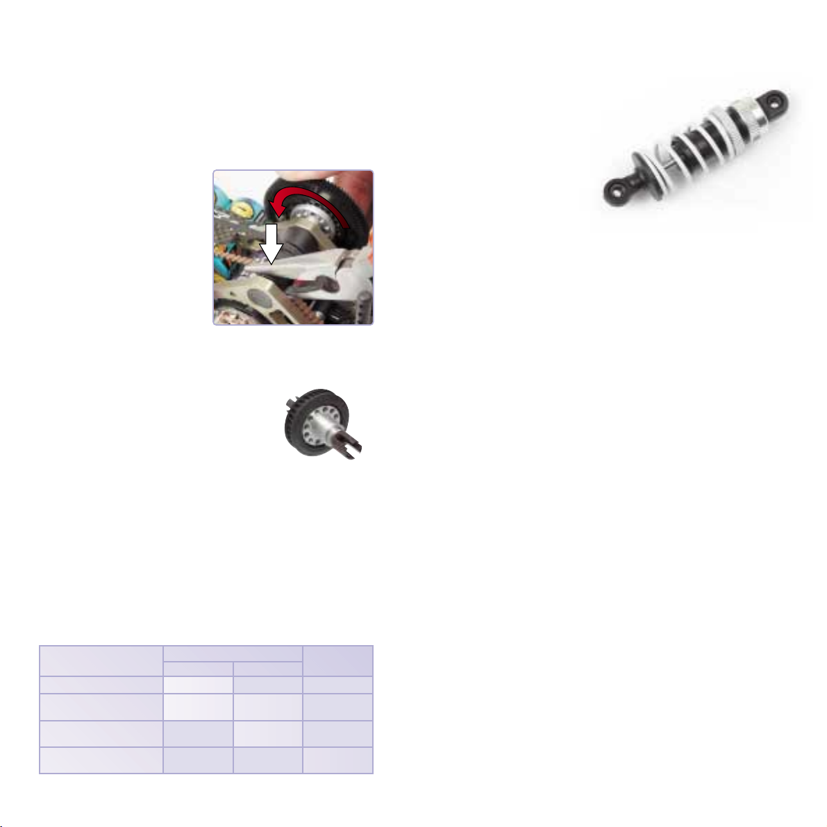
SSpprriinnggss::
The shock springs support the weight of the car. Different spring tensions
determine how much of the car's weight is transferred to the wheel relative to
the other shocks. The spring tension also influences the speed at which a
shock rebounds from compression.
Spring selection depends on the whether the track is fast or slow, or has
high or low traction.
••SSttiiffffeerr sspprriinnggss::Makes the car feel more responsive, more direct. The car will
react faster to driver input. Stiff springs are suited for tight, high-traction
tracks that aren't too bump . Usuall when ou stiffen the whole car, ou
lose a small amount of steering. Stiffer springs reduce chassis roll.
••SSoofftteerr sspprriinnggss::Better for bump and ver large and open tracks. The can
also make the car feel as if it has a little more traction in low-grip
conditions. Springs that are too soft make the car feel sluggish and slow.
Softer springs allow more chassis roll.
••SSttiiffffeerr ffrroonntt sspprriinnggss::The car will be more stable, but will have less front
traction and less steering. It will be harder to get the car to turn, the turn
radius will be bigger. The car will have a lot less steering exiting corners.
On ver high-grip tracks, if the track itself feels tack or stick , ver stiff
springs are preferred.
••SSoofftteerr ffrroonntt sspprriinnggss::The car will have more steering, especiall in the middle
and exit of the corner. Front springs that are too soft can make the car
oversteer.
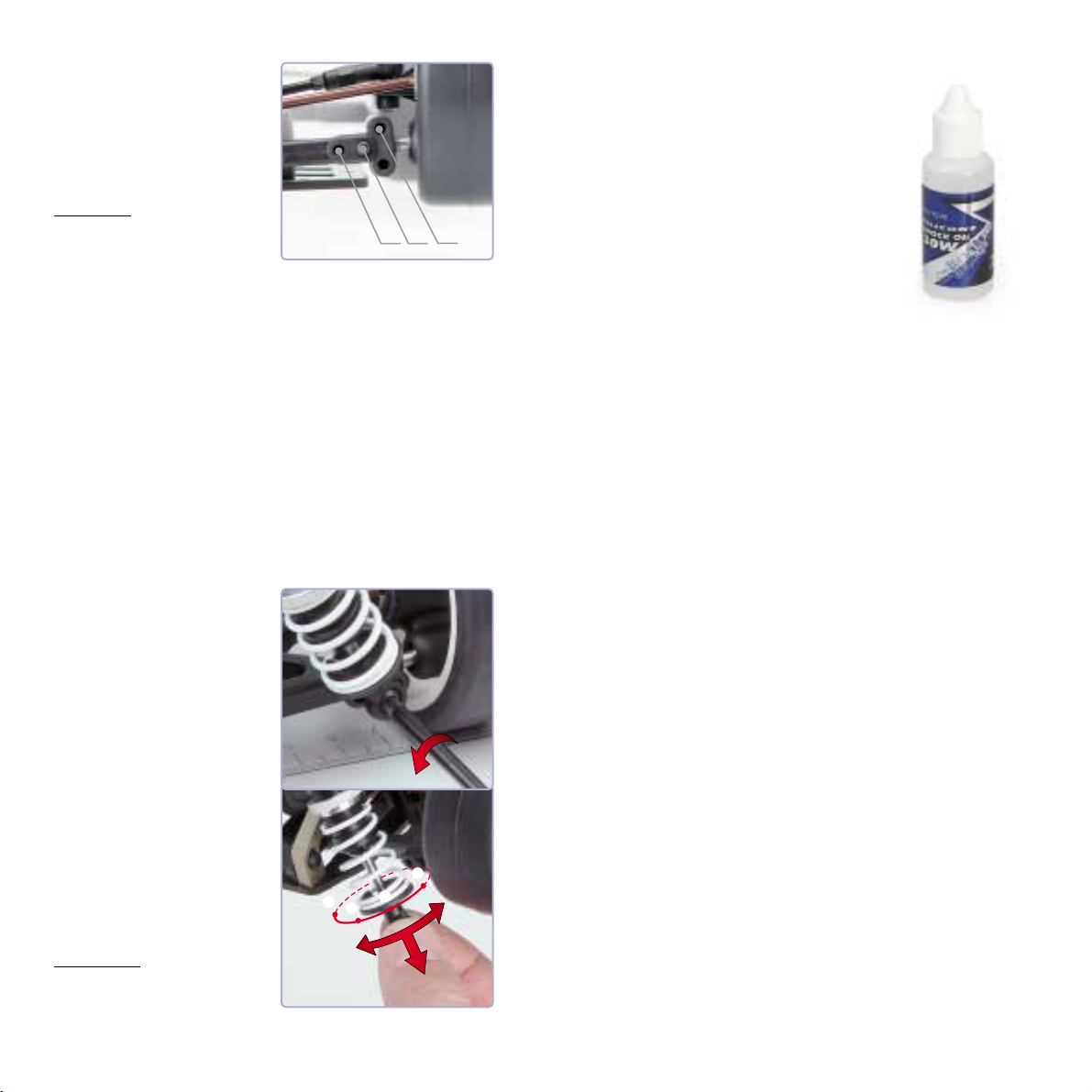
Final Adjustments
To let the front wheels freewheel, hold the locknut securely with pliers, then
rotate the spur gear backwards. The locknut will back away from the fixed
pulley and move towards the left bulkhead.
NOTE: Pull the fixed pulley away from the one-way pulley to let the front belt
move freely without binding.
22.. TTiigghhtteenneedd oonnee--wwaayy ppuulllleeyy
The pulley should be tightened under
slippery conditions, if you need to
lessen steering, or if heavy braking is
needed.
To tighten the one-way pulley, hold the
locknut securely with pliers, then rotate
the spur gear forwards. The locknut
will tighten the fixed pulley and move
towards the right bulkhead.
ONE-WAY FRONT DIFFERENTIAL (available option)
What is the difference between the one-way pulley
and the optional one-way diff?
The one-way pulley allows differential action under
acceleration. That means that when going through a
turn on throttle, if the inside wheel breaks traction, it
can still "unload" and prevent the outer wheel from
getting any power. The optional front one-way
differential (#30 5 00) gets around this problem by giving each wheel its
own independent one-way bearing. This way, the two wheels can rotate at
different rates, like with a regular differential, but on throttle, if one wheel
looses traction, the other one still gets power to pull the car through the turn.
Keep in mind that when using the one-way pulley with a loose setting or
when using the one-way differential, no drag brake should be used. Most
racers will also find it more convenient to set their radio to give less braking
action (use the throttle EPA setting); this will prevent the rear tires from
locking unexpectedly.
Use table below as a general guideline for the use of the one-way pulley and one-way differential.
TRACK SURFACE ONE-WAY PULLEY ONE-WAY FRONT
LOCKED LOOSENED DIFFERENTIAL
Low tra tion
Medium tra tion
(slow, tight orners)
High tra tion
(slow, tight orners)
High tra tion
(fast, sweeping orners)
✔
✔✔
✔✔
Final Adjustments
10
9