Xtracycle SWOOP User manual

-
Swoop assembly Manual

02
Record the serial number and the Shimano key number
which can be found on the label on the side of the box. Keep
these numbers in a secure place since they might be needed
in case somethig happens to your bike or you lose your
Shimano key. The serial number is the number under the bar
code next to "Frame No:". For the Swoop, this will start with
SWP (the barcode show here is for a Stoker). The key number
is the number under the bar code next to "Key No:".
01 - Open the bike box
Look over the box for signs of shipping damage. If damage
is present, please take pictures in case a shipping damage
report needs to be filed.
Assembling the
xtracycle swoop
2
Tools needed
3 mm Allen wrench
4 mm Allen wrench
5 mm Allen wrench
6 mm Allen wrench
Snippers / scissors
10 mm socket wrench
Pedal wrench or 15 mm wrench
Bicycle grease
Electrical tape
Needlenose pliers (optional)
03
Cut away the yellow banding straps holding the box closed.

3
04
Open the box.
05
Inspect the contents and look again for any signs of
shipping damage.
06
Remove and set aside the small parts box, the KickBack 3
and the seat with post.
07
Cut the string attaching the rear of the bike to the end of
the box.

4
10 - Charge the battery
Remove the battery keys secured to the handlebars.
11
Unlock your battery and remove it by rotating it away from
the bike.
08
With a friend, lift the bike out of the box and set it on your
work surface.
09
Remove the zip-ties holding the front wheel to the frame and
set it aside.

5
12
Find the battery charger and domestic power cable in the
small parts box. Locate the charging port on the drive side
of the battery. Pull back the rubber cover and plug in the
charging cable.
13
Make sure the charge indicator lights begin to blink green.
A full charge will take a few hours but you will be able to use
the battery with a partial charge by the time you are done
setting up your bike.
Please note: It is also possible to charge the battery while
it is installed on the bike, but for the initial assembly you
will need the extra room.
Also note that the battery will not supply power while it
is charging.
14 - Install the KickBack 3
Remove the KickBack3 packaging and locate the included
hardware kit consisting of two U-bolts, a rectangular
mounting plate, four M6 washers & nuts, and an M5
set-screw.
15
Under your bike find the kickstand mounting shelf and the
threaded set-screw hole.

6
17
Install the first U-bolt on the drive side of the bike. Fit an
M6 washer and nut onto the forward threads, until just
finger-tight.
Place another washer and nut on the other end of the U-bolt,
and secure both nuts with a 10 mm socket tool, being
mindful to tighten each end of the U-bolt evenly.
18
Place the second U-Bolt on the non-drive side and position
the small mounting mounting plate in place on the forward
threads. Secure it with an M6 washer and nut.
Secure the other end of the U-bolt with the remaining M6
washer and nut.
19
Go back to all four nuts and tighten everything with the
10 mm socket tool.
16
Rest the back of the kickstand mounting plate on the
mounting shelf and use a 3 mm Allen wrench to thread the
M5 set screw in order to hold the kickstand in place.

7
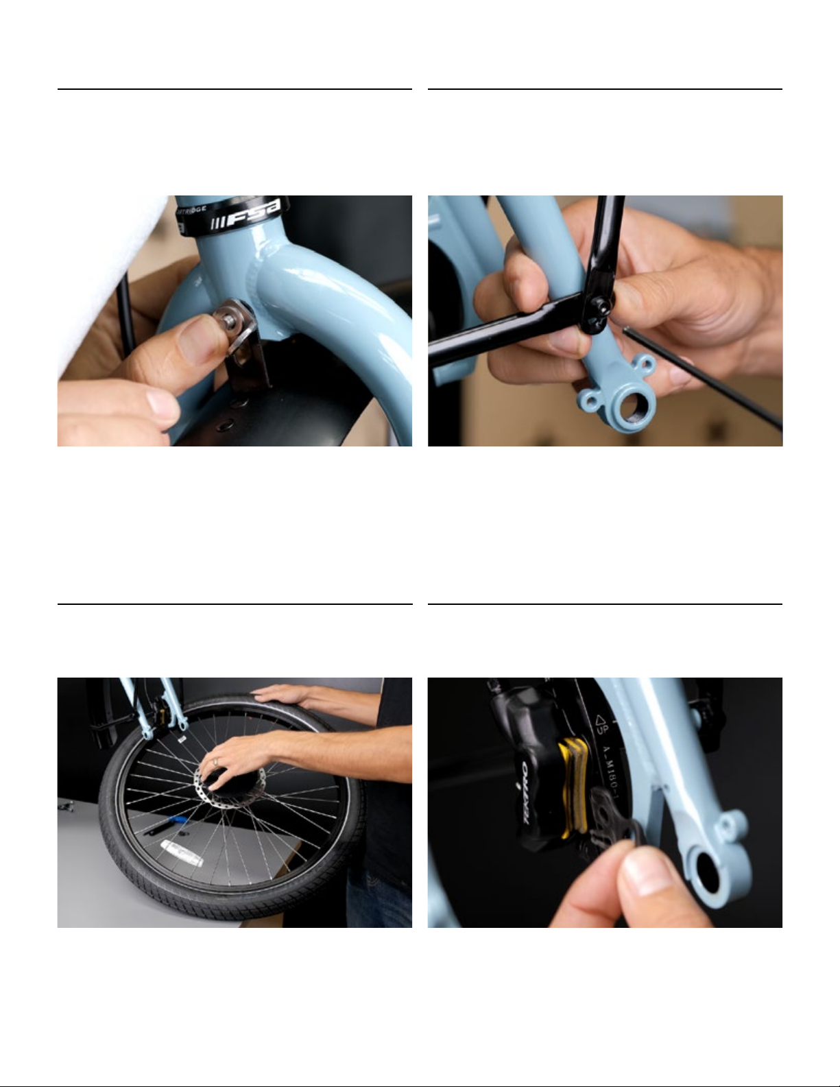
21
Remove the packaging around the fork and fender. Remove
the thru-axel with a 6 mm Allen wrench.
22
From the smal-parts box, locate the fender mount L-bracket,
M6 x 50 mm bolt, two M6 washers, M6 nyloc nut and two
M5 bolts.
23
Insert the M6 x 50 mm bolt and one M6 washer in the upper
fork hole.
20 - Install the front fender & wheel
Carefully lift the front of the bike and deploy the kickstand.
8
25
Usa a 4 mm Allen wrench to attach the outer support arms
of the fender to the lower fork-mounting points with the two
M5 bolts.
26
Remove the packaging from the front wheel.
27
Remove the disc brake-pad spacer.
24
Bring the front fender into position by hanging the mounting
tab from the M6 x 50 mm bolt and holding it in place with
the L-bracket, M6 washer & M6 nyloc nut. You will tighten this
in a moment.

9
30
Returning to the fender, tighten the upper bolt with a 4 mm
Allen wrench and an 8 mm socket tool.
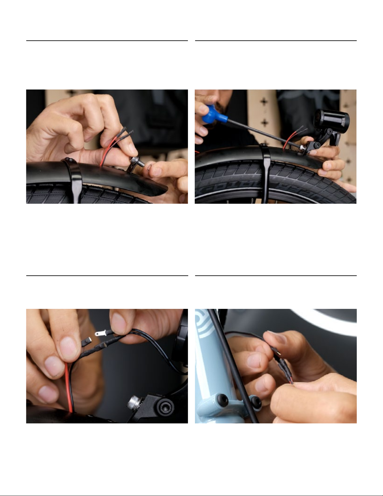
31 - Mount the front light
The fender-mounted headlight is secured with an M6 nut, M6
bolt, flat washer and spider washer.
Slide the nut into the slot on the front of the mounting arm of
the headlight.
29
Re-insert your thru-axel, and tighten with a 6 mm
Allen wrench.
28
Rotate your front wheel into position. Be mindful to seat the
disc brake rotor neatly between the brake pads.
10
34
Connect the fender headlight leads by matching black to
black and red to black-with-gray stripe.
35
Connect the leads at the top of the fork by matching black to
black and red to red.
33
Use a 5 mm Allen wrench to thread the bolt into the nut
through the light mounting arm.
32
Place the flat washer over the M6 bolt and insert the bolt
through the light mounting tab on the fender.
Then place the spider washer on the bolt.
Table of contents
Other Xtracycle Bicycle manuals

Xtracycle
Xtracycle RFA User manual

Xtracycle
Xtracycle STOKER User manual

Xtracycle
Xtracycle RFA Sport User manual

Xtracycle
Xtracycle RFA 2021 User manual

Xtracycle
Xtracycle RFA User manual

Xtracycle
Xtracycle STOKER User manual

Xtracycle
Xtracycle Swoop 4ST1000 User manual

Xtracycle
Xtracycle Freeradical User manual

Xtracycle
Xtracycle Swoop 2021 User manual

Xtracycle
Xtracycle EdgeRunner Swoop User manual


