XTRONIC 5040-XR3 User manual


- 1 -
TABLE OF CONTENTS
Product Specifications......................................................2
Package Contents .............................................................3
Safety Precautions ............................................................4
Initial Set-up.......................................................................5
Unit Interface......................................................................6
Operating Instructions......................................................8
Features............................................................................10
Celsius / Fahrenheit Conversion ...................................10
Automatic / Manual Mode..............................................10
Calibration Function ......................................................11
Maintenance.....................................................................14
Unit ................................................................................14
Soldering Tip Preparation & Care..................................14
Changing the Soldering Tip ...........................................15
Install/Remove Hot Air Nozzles .....................................15
Replacing the Soldering Iron Heating Element .............16
Replacing the Hot Air Gun Heating Element .................17
Troubleshooting ..............................................................18
Warranty ...........................................................................20
Contact Information ........................................................22

- 2 -
PRODUCT SPECIFICATIONS
MODEL #5040-XR3
Power Consumption 1270 Watts ± 5%
Dimensions 8.7 x 3.1 x 12.6 in / 22.1 x 7.9 x 32.0 cm
Weight 6.6 lbs / 3.0 kg
Working Environment 32°F ~ 122°F / 0°C ~ 50°C
Storing Environment -68°F ~ 176°F / -20°C ~ 80°C
HOT AIR REWORK
Airflow Type Brushless Fan (Spiral Wind)
Airflow Volume 31 L/min
Temperature Range 212°F ~ 896°F / 100°C ~ 480°C
Temperature Stability ± 1°C
Cord Length ≥ 39.4 in / 100 cm
SOLDERING IRON
Temperature Range 392°F ~ 896°F / 200°C ~ 480°C
Temperature Stability ± 1°C
Grounded Tip Voltage < 2 mV
Tip Impedance < 2Ω
Cord Length ≥ 39.4 in / 100 cm
PREHEATING STATION
Temperature Range 122°F ~ 752°F / 50°C ~ 400°C
Temperature Stability ± 2°C
Heating Area 4.7 in x 4.7 in / 12 cm x 12 cm

- 3 -
PACKAGE CONTENTS
1 – X-Tronic #5040-XR3 Multifunction Main Unit
1 – X-Tronic Soldering Iron with 900M-T-I Tip Installed
1 – X-Tronic Hot Air Gun
1 - Soldering Iron Holder
1 - Blue Wet Cleaning Sponge
1 - Solder Roll Holder
1 – Stainless Steel, Anti-static Tweezers
1 – Wick De-soldering Braid
1 - IC Popper
4 – Hot Air Nozzles (Assorted Sizes & Shapes)
9 – Soldering Iron 900M Tips Variety Pack
• 900M-T-I
• 900M-T-B
• 900M-T-K
• 900M-T-1C
• 900M-T-2C
• 900M-T-3C
• 900M-T-1.2D
• 900M-T-1.6D
• 900M-T-2.4D

- 4 -
SAFETY PRECAUTIONS
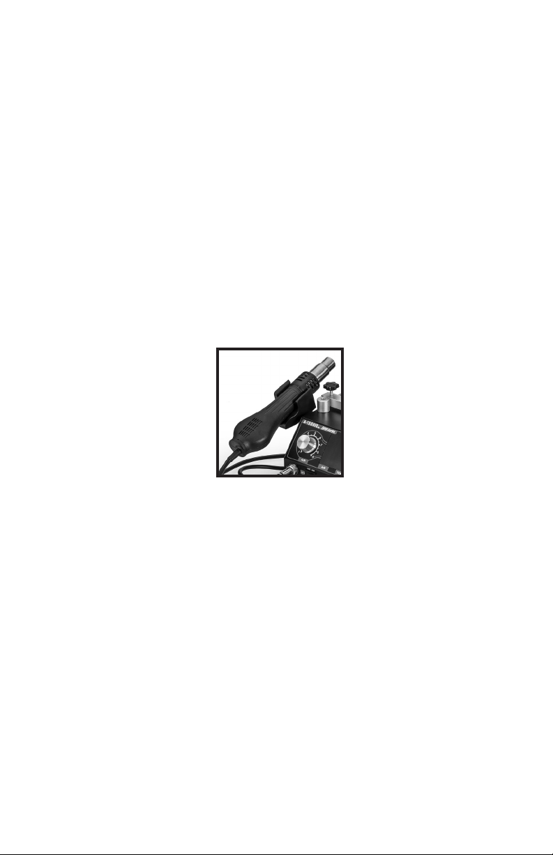
1. When initially powering on the unit and when powering down, the
hot air gun should ALWAYS be in the side holder. It should NEVER
be in the vertical position when the unit is initially turned on. If it is
used vertically with the appropriate air flow, it MUST be returned to
the side holder for cool down.
2. When using the hot air gun in the vertical holder the air flow MUST
be turned up to at least 4 or higher the entire time the hot air gun is
in this position. If the air flow is not sufficient the life of the heating
element will be greatly reduced.
CAUTION! IF #2 IS NOT FOLLOWED
The hot air gun will overheat and may cause the polymer on the front of
the hot air gun to melt and get red hot from the intense heat.
3. Never use the soldering iron or the hot air gun near any flammable
substance, material, or gas.
4. Never touch the metallic components of the soldering iron or the
hot air gun while they are in use. They are extremely hot and will
cause serious burns instantly. Allow the unit to properly cool to
room temperature before attempting to touch them.
5. Never point the hot air gun towards human skin. The air exiting the
hot air gun is VERY HOT and WILL cause serious burns.
6. Do not use pliers or any other tool to manipulate hot air nozzles.
7. Do NOT try to reform nozzle attachments into other shapes.
8. Never place anything flammable on or near IR Preheating Plate.
9. Never Touch the IR Preheating Plate or surrounding chassis while
in operation.
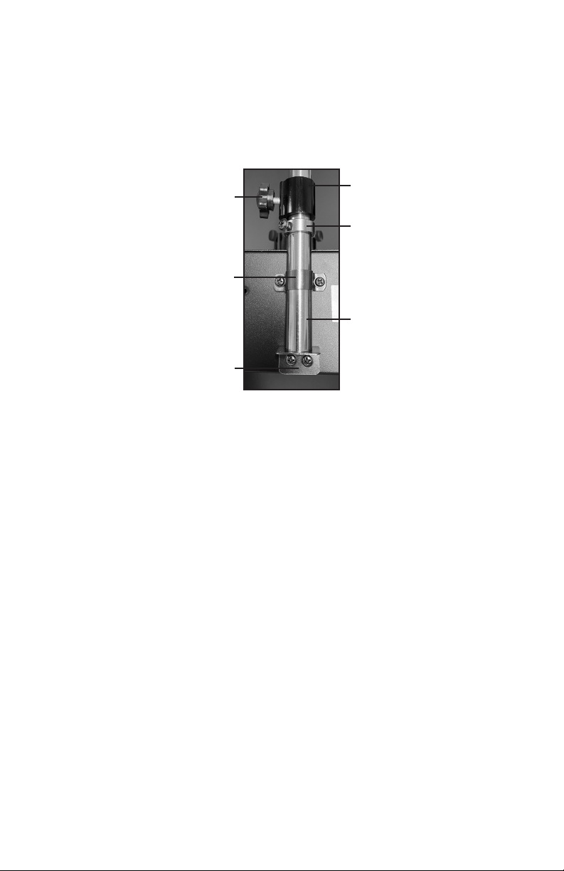
10. Ensure a minimum distance of 2mm while using the hot air gun in
the hands-free telescopic hot air gun holder.
11. Always keep the hot air gun moving, unless reflowing large chips.

- 5 -
INITIAL SET-UP
1. Unpack all of the contents of the X-Tronic #5040-XR3 kit.
2. Inspect the unit and accessories for any damage. If damage is
detected, please contact X-Tronic immediately.
3. Assemble the hands-free telescopic hot air gun holder
Thumb Screw
U-Shaped Bracket
L-Bracket
Silver Retaining
Collar
Vertical Hot Air
Gun Holder
Metal Rod
Note: The Vertical Hot Air Gun Holder and Silver Retaining Collar will be
further up on the Metal Rod when fully assembled.
a. Slide the silver retaining collar onto the metal rod. Install one of
the small dark gray screws into the hole on the silver retaining
collar to secure its placing on the metal rod.
b. Attach the L-bracket to the bottom of the metal rod using the
large silver screw.
c. Attach the L-bracket and rod assembly to the back of the unit
using the 2 holes in the lower center and 2 of the smaller dark
gray screws.
d. Secure the rod to the back of the unit using the U-shaped
bracket and the last two of the smaller dark gray screws.
e. Slide the vertical hot air gun holder assembly over the rod
and secure it with the included thumb screw. Adjust the silver
retaining collar so it is just below the hot air gun holder assembly
to provide additional support.
f. Insert the 4 black thumb screws into the adjustable rail system
around the IR Preheating Plate.
4. Attach the soldering iron to the unit using the soldering iron
connection.
5. Place the soldering iron into the soldering iron holder.

- 6 -
6. Attach the hot air gun holder to the side of the unit using the 2
screws that are in the side of the unit.
7. Place the hot air gun into the hot air gun holder.
8. Ensure all of the connections are secure and correct before
applying power to the unit.
9. Ensure the safety fuse (found on the back of the unit above the
power receptical) is installed and in good working order before
applying power to the unit.
10. Plug the power cord into a GROUNDED AC wall outlet.
11. Turn on the main power switch located on the back of the unit.
12. Power on the unit.
a. Soldering Iron
i. Attach the desired tip to the soldering iron.
ii. Power on the soldering iron with the Iron power switch.
iii. Adjust the soldering iron temperature by pressing the
soldering iron ꜛ and ꜜ buttons.
b. IR Preheating Station
i. Power on the preheating plate with the IR Preheating Plate
switch.
ii. Adjust the preheating plate temperature by using the IR
preheating Plate ꜛ and ꜜ buttons.
c. Hot Air Gun
i. Attach the desired nozzle to the hot air gun and place the
hot air gun in the side holder.
ii. Turn on the hot air gun by with the Hot Air power switch.
iii. Adjust the hot air temperature by using the hot air gun
ꜛ and ꜜ buttons.

- 7 -
USER INTERFACE
MODEL#5040-XR3
1. X-Tronic #5040-XR3 Main Unit
2. Hot Air Gun Receptical (Hardwired)
3. Soldering Iron Receptical
4. Power Switches
a. Soldering Iron
b. Hot Air Gun
c. IR Preheating Plate
d. Main - Located on back of unit (Not Pictured)
5. Temperature Displays
6. Adjustment
a. Soldering Iron Temperature
b. Hot Air Temperature
c. IR Preheating Plate Temperature
d. Air Speed

- 8 -
OPERATING INSTRUCTIONS
SOLDERING IRON
• Before turning on the unit, ensure that the soldering iron is in the
soldering iron holder and the hot air gun is in the hot air gun holder
on the side of the unit.
• When using the soldering iron for the first time, be sure to allow the
iron to come to the proper temperature then clean and tin the tip to
provide longer life expectancy.
• Do not use excessive force when installing/removing soldering iron
tips.
HOT AIR GUN
• Before turning on the unit ensure that the hot air gun is in the hot
air gun side holder. The hot air gun needs to be in this position
EVERY TIME the unit is powered on.
Hot Air Gun
Side Holder
• Upon first use, the tube on the soldering iron may discolor a bit due
to the combination of the material composition and high heat. This
is perfectly normal and expected behavior.
• Upon first use, white smoke may be visible from the hot air gun and
will go away shortly after heating. If the unit keeps smoking, refer
to troubleshooting section or contact X-Tronic International
(contact information is on the back cover of this manual).
• When “---” is displayed on the LED display, the outlet temperature
of the hot air gun is below 100°C, the handle has been properly
replaced into the side holder, and the unit is in standby mode.
• Do not use excessive force when installing/removing hot air
nozzles Do not over tighten the bolt on the hot air attachments.
• When using the small nozzle attachment for the hot air gun, set
airflow to the maximum value to keep the hot air heating element
from overheating and breaking.

- 9 -
HOT AIR GUN IN HANDS-FREE TELESCOPIC ASSEMBLY
NOTE: The hot air gun should NEVER be in the vertical position when
the unit is initially turned on. It can be used vertically with the
appropriate air flow and then should be returned to the side holder
for cool down.
Hot Air Gun in Hands-Free
Telescopic Assembly
1. Attach the cord to the side of the machine using the attached clip.
2. With the nozzle pointing down, insert the hot air gun into the hot air
gun holder.
3. Adjust the bottom silver screws first to center the hot air gun nozzle
in the center of the holder.
4. Adjust the black thumb screws to snuggly hold the plastic just
above the metal area of the hot air gun to center and secure it in
the assembly
• When using the hot air gun in the vertical holder, the air flow must
be turned up to at least 4 or higher the ENTIRE TIME the hot air
gun is in this position. If the air flow is not sufficient the unit will
be damaged and the life of the heating element will be greatly
reduced.
CAUTION! IF THIS IS NOT FOLLOWED the hot air gun will
overheat and may cause the polymer on the front of the hot air gun
to melt and get red hot from the intense heat.
• After using the hot air gun, place it back into the side holder, and
allow the unit to initiate the cool down cycle until the display reads
“---”. Then power can be turned off.
• Always shield the surrounding components while using the hot air
gun. Failure to do so could cause other components to become
unsoldered and blow off of the board.

- 10 -
FEATURES
CELSIUS / FAHRENHEIT CONVERSION
1. Turn on the power switch(es) for the component(s) that require
temperature unit conversion.
2. Press and hold the Hot Air and Iron $buttons simultaneously for 3
seconds, the Hot Air display will show A1.
3. Press the Iron $button and the “C” or “F” will show in the Hot Air
and Iron displays.
4. Press the Hot Air $button to change to “F” or the Hot Air #button
to change to “C”.
5. Once the desired temperature unit is selected, let the unit stand for
5 seconds. The unit will automatically store the selection.
AUTOMATIC VS. MANUAL MODE FOR HOT AIR GUN
The hot air gun has a built in safety feature where every time the
hot air gun is placed in the side holder it will go into Cool Down and
Standby Mode. This ensures that the hot air gun is not left running
for long periods of time causing undo wear on the unit. This is
called Automatic Mode and is enabled for your safety.
The unit does have the option to go into Manual Mode so that the
hot air gun will NOT go into Cool Down and Standby Mode when
placed in the side holder.
ATTENTION: This unit should ALWAYS be used in Automatic mode for
safety purposes. It is very rare that manual mode is needed.
Using Manual mode will also greatly reduce the life of the heating
element in the hot air gun.
1. Turn on the power switches to the component(s).
2. Press and hold the Hot Air and Iron $buttons simultaneously for 3
seconds, the Hot Air display will show A1.
3. Press the Hot Air $button to change to “0” (Manual Mode) or the
Hot Air #button to change to “1” (Automatic Mode).
4. Once the desired conversion is selected, let the unit stand for 5
seconds. The unit will automatically store the selection.

- 11 -
TEMPERATURE CALIBRATION FUNCTION
When is it time to Calibrate your Soldering & Hot Air Station?
All X-Tronic Stations come with a high quality heating element
in the soldering iron and hot air gun that are calibrated to within
±1.8°F/1.0°C of the temperature that is shown on the LED Display.
While calibrating to the exact temperature is the ultimate goal,
this heating element and tip/nozzle design are as close as can be
achieved with this technology.
The age of the heating element, the hours of use, and the
temperature at which the soldering iron/hot air gun are regularly
used will affect the life of the heating element and can cause
fatigue. When a heating element begins to fatigue, the heat that
is transferred to the tip/blowing air from the heating element will
begin to drop. If the typical temperature used to solder/desolder
is not working as well as when it was new, then it might be time to
calibrate the unit.
Notes:
• The heating elements are a consumable part for soldering
irons and hot air guns. There will come a time when the
heating element stops working due to age and/or too much
deterioration. At this point, it will need to be replaced and
cannot be calibrated. Heating elements for this unit can be
found on our website (XTronicUSA.com).
• For best results, you should only calibrate the temperature for
one component at a time.

- 12 -
CALIBRATION INSTRUCTIONS FOR SOLDERING IRON
1. Turn on the power switch for the soldering iron.
2. Set the desired temperature for the soldering iron on the unit.
3. Let the set temperature stabilize.
4. Measure the heat at the soldering tip using a high quality and
well calibrated soldering tip tester. If the temperature shown on
the unit’s display does not reflect the temperature shown on the
tester, continue with steps 5-7.
5. Press and hold the up and down buttons for the soldering iron,
three decimal points will appear in the temperature display to
indicate the soldering iron is in calibration mode.
6. Press the up or down buttons to select the temperature the
soldering iron is actually measuring when tested.
7. When the calibrated temperature is set, press the up and down
buttons simultaneously to secure the adjusted temperature in
memory and exit this mode.
IMPORTANT - PLEASE READ
Infrared (IR) Thermometers should NOT be used to measure the
temperature of the soldering tip as they often provide inaccurate
readings. All IR Thermometers are different and the capability
depends on the Distance to Spot (D:S) ratio of the model being
used. Many IR thermometers have a D:S ratio of 8:1 or 12:1 which
means that the thermometer needs to be a distance of 8” or 12” in
order to read a 1” spot size.
The tip of a soldering iron is approximately 2 to 3 mm (.07-.11”),
requiring the thermometer to be 0.8” or 1.2” away from the tip.
However, the IR thermometer also has a minimum distance it
needs to be away from the object.
Most IR thermometers will not be capable of measuring such a
small spot size and will provide disappointing calibration results.

- 13 -
CALIBRATION INSTRUCTIONS FOR HOT AIR GUN
Before measuring the temperature or calibrating the unit, ensure all
nozzles have been removed from the hot air gun.
1. Turn on the power switch for the hot air gun.
2. Set the desired temperature for the hot air gun on the unit.
3. Let the set temperature stabilize.
4. Measure the heat of the hot air using a high quality and well
calibrated hot air tester or an infrared thermometer.
(If using the infrared thermometer, aim it approximately three
inches away from the end of the hot air gun.) If the temperature
shown on the unit’s display does not reflect the temperature shown
on the tester, continue with steps 5-7.
5. Press and hold the up and down buttons for the hot air gun, three
decimal points will appear in the temperature display to indicate
the hot air gun is in calibration mode.
6. Press the up or down buttons to select the temperature the hot air
gun is actually measuring when tested.
7. When the calibrated temperature is set, press the up and down
buttons simultaneously to secure the adjusted temperature in
memory and exit this mode.

- 14 -
MAINTENANCE
UNIT
1. Keep the unit plugged into a grounded outlet at all times while
operating.
2. Keep the unit and all of the components free from dirt, debris, and
liquid at all times.
3. Make sure the power cord is plugged in correctly into a ground
outlet and safely off the floor to prevent accidents.
4. Avoid letting any of the cords hang off the side of the table or
workbench keeping them in the immediate workspace.
5. Wipe the unit down, as needed, with a dry, static-free cloth.
SOLDERING TIP PREPARATION & CARE
1. Keep the soldering tip properly tinned. Always use solder with
sufficient rosin flux or the tip will degrade. A well tinned tip will be
bright all over when hot, with no dull or discolored spots.
2. To tin the iron, do the following:
a. Plug in the iron and allow it to reach solder melt temperature.
b. Flood the tip with solder and let it stand for one minute.
c. Apply more solder to the tip, allow it to idle for one or two more
minutes, wipe it lightly on the sponge. Do not remove all of the
solder, but use the sponge to remove excess solder and wipe
solder onto non-tinned areas.
3. Do not file or attempt to reshape the tip. This will destroy the
plating and shorten tip life. Do not use chloride and acid fluxes;
they will also shorten tip and heater life.
4. For maximum tip life, always apply solder to the heated
connections or joints. Repeated application of solder directly to the
tip will shorten the tip life.
WARNING: Do NOT use anti-seize or any other lubricant on the tip
retainer or heater of the soldering iron.

- 15 -
CHANGING THE SOLDERING TIP
1. Turn off the soldering station, unplug the power cord from the
power source and allow the soldering iron to cool down to room
temperature. Never attempt to remove the tip while the iron is
hot.
2. Unscrew the larger metal tip retaining screw ring at the bottom of
the soldering irons metal shaft. Slide off or remove the soldering tip
retaining collar. Now, remove the tip by sliding it forward.
3. Slide a new tip over the exposed ceramic heating element, slide
the metal retaining collar over the new soldering tip back onto the
soldering iron.
4. Tighten the metal tip retaining screw ring to snug the tip into place.
Do not over tighten the tip retaining screw
5. Plug the soldering iron AC cord into a grounded outlet to resume
soldering.
INSTALL/REMOVE HOT AIR NOZZLES
1. Turn the power off to the unit and unplug it from the power source.
2. Allow the hot air gun and attachment to reach room temperature
before proceeding.
3. Do not use excessive force when installing/removing hot air
attachments. Loosen the screw and nut from the attachment
by holding the nut with a pair of pliers and turning the screw
counterclockwise.
4. Slide the attachment off of the metallic shaft of the hot air gun.
5. Repeat in the reverse order for installation. Do not overtighten the
screw and nut on the hot air gun.

- 16 -
REPLACING THE SOLDERING IRON HEATING ELEMENT
Cord
Soldering Tip
Collar
Metal Tip
Retaining
Screw Cap
Bakelite Screw Cap Spring
Heating
Element
Ergonomic
Grip
Handle
1. Turn off the unit and unplug it from the outlet. Allow the soldering
iron to cool down to room temperature.
Never attempt to handle the tip while the iron is hot.
2. Unscrew the Black Bakelite Screw Cap and slide off the full tip
assembly.
3. Push the Cord through the bottom of the soldering iron while
simultaneously pulling gently on the heating element to expose the
heating element circuit board.
4. De-solder the 2 Thin (red or white) wires and the 2 Thick (blue)
wires that have heat shielding on them from the circuit board and
pull the heating element away from the board.
Please take note of the location of the wire thickness/color for
installation of new heating element (see diagram below).
5. On one side of the circuit board solder a thin wire to 1and a thick
wire to 2(see diagram below).
6. Flip the circuit board over and solder a thin wire to 3and a thick
wire to 4(see diagram below).
7. Pull the cord back gently and align the circuit board to the slots on
the iron so the cord can be pulled back to its original position.
8. Replace black Bakelite Screw Cap and screw back on and hand
tighten - Do NOT over-tighten.
9. Install the soldering tip, slide the metal soldering tip retaining collar
and hand tighten it. Plug the AC cord back into a grounded outlet.
SIDE A SIDE B
1 2 3 4
NOTE: The wires on the heating element can be soldered onto either
side of the circuit board, as there is no polarity for the element.

- 17 -
REPLACING THE HOT AIR GUN HEATING ELEMENT
Handle Cover -
Side 1
Heating
Element
Handle
Cover -
Side 2
Mica Paper
Discharge Tube
Nozzle
Retaining Cap
Circuit
Board
Fan
Reducer
Fan
1. Turn off the unit and unplug it from the outlet. Allow the hot air gun
to cool down to room temperature.
Never attempt to handle the gun while it is hot.
2. Slide the ergonomic grip up and unscrew the retaining cap, pull the
ergonomic grip down off the handle.
3. Unscrew both of the screws at the base of the handle and separate
the two handle sides.
4. Pull the heating element out of the Mica Paper and Discharge
Tube, being careful not to disconnect grounding wire.
5. Unscrew the two screws holding the circuit board in place.
6. Desolder the four wires to the circuit board - Please take note of
the location of the 4 wires thickness/color for installation of new
heating element.
7. Solder the new heating element into place.
8. Reassemble the hot air gun.

- 18 -
TROUBLESHOOTING GUIDE
Nothing appears to
happen when turning on
the unit
• Check to ensure that the power cord is
securely plugged into the back of the
unit and that the unit is plugged into a
grounded, working outlet.
• Ensure the main power switch on the
back of the unit is switched to the on
position.
• Ensure the appropriate component’s
power switch is turned on (front of unit).
• Check for a blown fuse on the main
power input and replace it if needed.
• Contact X-Tronic (info on back cover).
Soldering Iron “Rattles” • This is expected behavior. The “rattle” is a
small ball that allows the unit to determine
when the soldering iron is not in use and
it should go into Sleep Mode.
S-E Error • The unit is no longer sensing the element
- the heating element may be cracked
or worn out and needs to be replaced.
Replacements can be purchased on our
website: www.XTronicUSA.com.
Soldering tip is not
heating up as expected
• Ensure the soldering iron is not damaged
and in good working condition.
• The soldering tip could be oxidized, it is
important to always tin the tip and keep it
clean. See Soldering Tip Preparation on
page 5.
• The heating element may need to
be replaced. Replacements can be
purchased on our website: www.
XTronicUSA.com.
Soldering iron is not
heating as expected
• Ensure the soldering iron is securely
attached to the unit.
• Soldering tip may need to be tinned
• Soldering iron may need to be
calibrated.
• The heating element may need to be
replaced.
• Contact X-Tronic (info on back cover).
Table of contents
Other XTRONIC Soldering Gun manuals

XTRONIC
XTRONIC 6040-PRO-X User manual

XTRONIC
XTRONIC 3060-PRO User manual

XTRONIC
XTRONIC 8020-XTS User manual

XTRONIC
XTRONIC 4040-PRO-X User manual

XTRONIC
XTRONIC 3060-XTS User manual

XTRONIC
XTRONIC 9070-XR3 User manual

XTRONIC
XTRONIC 4008-PRO-X User manual

XTRONIC
XTRONIC 3050-PRO-X User manual

XTRONIC
XTRONIC 3090-PRO-X User manual

XTRONIC
XTRONIC 4010-PRO-X User manual