XTRONIC SX-90 User manual


- 1 -
PLEASE READ THESE INSTRUCTIONS BEFORE USING YOUR
NEW X-TRONIC MODEL #SX-90 MIRCO SOLDERING STATION
TABLE OF CONTENTS
Product Specifications......................................................2
Package Contents .............................................................2
Safety Precautions ............................................................3
Unit Diagram ......................................................................4
Initial Set-up.......................................................................4
User Interface.....................................................................5
Operating Instructions......................................................6
Features..............................................................................6
Celsius / Fahrenheit Conversion .....................................6
Mute/Unmute Function ....................................................6
Memory Preset Channels................................................6
Sleep Function ................................................................7
Temperature Kicker Bar...................................................7
Calibration Function ........................................................7
Maintenance.......................................................................9
Soldering Tip Care...........................................................9
Replacing the Fuse .......................................................10
Troubleshooting ..............................................................11
Warranty ...........................................................................12
Contact Information ........................................................14

- 2 -
PRODUCT SPECIFICATIONS
Model XTR-SX-PRO-X
Dimensions 6.5 x 5.25 x 10.0 in / 16.5 x 13.3 x 25 cm
Weight 4.0 lbs / 1.8 kg
Working Environment 32°F ~ 104°F / 0°C ~ 40°C
Storing Environment -4°F ~ 176°F / -20°C ~ 80°C
Storage Humidity 35% - 45%
Temperature Range 392°F ~ 932°F / 200°C ~ 500°C
Temperature Stability ± 1.8°F / 1.0°C (Static)
Grounded Tip Voltage < 1 mV
Tip Impedance < 1Ω
Display Type LED - Bright White
Cable Length (Material) ≥ 56 in / 144 cm (Silicone)
PACKAGE CONTENTS
• Main Power Unit
• 85 Watt Soldering Iron with Ergonomic Grip
• 56” Silicone Cord on Soldering Iron (Virtually NO Memory)
• Soldering Iron Holder - Attached to Main Unit
• Soldering Cord Extension Holder
• Anti-Static Grounding Wire
• Fuse Replacement (1) - (In the Fuse Holder in the Back of the Unit)
• Silicone Base Mat for Soldering Station & Holding Tools/Parts
• Brass Sponge Tip Cleaner - Inside Soldering Iron Holder
• Wet Sponge Tip Cleaner
• Power Cord

- 3 -
SAFETY PRECAUTIONS
1. Always use a grounded outlet for the unit.
2. Always turn the power off and unplug the unit when not in use.
3. Never use the soldering iron near any flammable substance,
material, or gas.
4. Never touch the metallic components of the soldering iron while
the unit is on. They are extremely hot and will cause serious burns
instantly.
5. Always turn the power off, unplug the unit, and let it fully cool down
before attempting to replace any parts (tips, heating element, etc.)
6. Use only genuine replacement parts for this unit.
7. Do not use the unit for any application other than soldering.
8. Do not tap the soldering iron against the work bench to remove
residual solder.
9. Do not modify the unit in any way.
10. When replacing consumable parts, only use approved
manufacturer parts.
11. Do not get the unit wet or use when your hands are wet.
12. The soldering process will produce smoke - ensure the area is well
ventilated.

- 4 -
UNIT PARTS
1. Soldering Cord Extension Holder
2. Soldering Iron
3. Soldering Iron Holder
4. Temperature Kicker Bar
5. Bright White LED Display
6. Preset Memory Buttons
7. Temperature Control Buttons
8. Wet Sponge Holder
9. Brass Sponge Holder
INITIAL SET-UP
1. Open the package and check that all parts are present and are
not damaged. If anything is missing or damaged, please contact
X-Tronic immediately for assistance (see back cover for contact
information).
2. Remove everything from the packaging.
3. Place the soldering cord extension holder in the bracket on the
right hand side (see #1 in drawing above).
4. Plug the soldering iron into the back of the unit and place the
soldering iron in the soldering iron holder (see #2 in drawing
above). Secure the core in the extension holder (optional).
5. The brass sponge is in the silicone opening right below the
soldering iron (see #9 in drawing above).
6. Wet the blue sponge and place in the space at the base of the
soldering iron holder (see #8 in drawing above).
7. Plug the 3-prong AC cord into the back of the unit and then into a
grounded outlet to prevent electric shock or injury.
2
78
9
1
6
4
5
3

- 5 -
USER INTERFACE
1
3
4
5
6
7
8
2
1. Celsius / Fahrenheit Indicator
2. Actual Temperature of the Soldering Iron Heating Element
3. Sound Indicator
4. Temperature Kicker Bar
5. 3 Preset Memory Channels
6. Temperature Setting Buttons
7. Set Temperature
8. PID (Proportional-Integral-Derivative) Self Correcting Indicator
Light
1
2
3
5
4
1. Soldering Iron Socket
2. Ground Wire Socket
3. Power Cord Socket
4. Fuse
5. Power Switch
FRONT
BACK

- 6 -
OPERATING INSTRUCTIONS
1. Place the soldering iron in the holder.
2. Turn the unit on with the power switch on the back of the unit.
3. Set the desired temperature using the TEMP UP and DOWN
buttons on the unit or by pressing one of the Preset Memory
Channels. This temperature will show in the lower right corner of
the display.
4. Wait for the unit to stabilize at the desired temperature. The actual
temperature of the heating element/soldering tip is displayed on
the top of the display. See page 5 for a detailed diagram of the
display screen.
5. Remove the iron from the holder and flood the tip with a good
quality rosin core solder-preferably 63/37 or 60/40 grade solder.
6. Wipe the tip across the moist sponge or dip the iron into the brass
sponge to remove excess solder. The tip should then be shiny.
7. The soldering iron is now ready to solder. Proceed according to
your standard working practice.
FEATURES
CELSIUS / FAHRENHEIT CONVERSION
To switch between displaying the temperature in Celsius or
Fahrenheit, press both the ▲ and ▼ and hold for 3 seconds. The
display will toggle between °C / °F.
MUTE / UNMUTE FUNCTION
The unit beeps when buttons are pushed or when the temperature
kicker bar is activated. To toggle between Mute and Unmute Mode,
press and hold the CH1 and CH2 buttons for 3 seconds. When the
unit is Muted a Red speaker with a line through it will appear, when
the unit is Unmuted a White speaker will appear.
SET MEMORY PRESET CHANNELS
Turn the unit on, set the desired temperature by pressing the
Temperature ▲ or ▼ arrows on the unit. Wait for the unit to
stabilize at the desired temperature. Then to set a Channel
Preset, press and hold the channel button to be programmed for 5
seconds. The unit will beep 3 times and the channel has been set.

- 7 -
SLEEP FUNCTION
When the soldering iron is placed in its soldering iron holder Sleep
Mode will be automatically be activated. The screen will switch
to “---”, “Sleep” will appear on the screen and the soldering iron
will cool down to 200°C (392°F). When the soldering iron is taken
out of the soldering iron holder, it will automatically come out of
sleep mode and will heat the iron up to the set temperature in
approximately 3 seconds.
TEMPERATURE KICKER BAR FUNCTION
The Temperature Kicker Bar, located above the LED display, will
kick the temperature up 72°C (162°F) for 15 seconds when any
part of the tip/heating element cartridge or metal circle on the
soldering iron briefly touch the kicker bar.
{
Note: Do NOT use the tip to activate the kicker bar, as it may damage
the tip.
This feature can be turned off so the Temperature Kicker Bar will
not activate when touched by pressing and holding the CH2 and
CH3 buttons for 3 seconds. The display will indicate OFF or ON.
CALIBRATION FUNCTION
When is it time to Calibrate your Soldering Station?
All X-Tronic Soldering Stations come with a high quality ceramic
heating element in the soldering iron that is calibrated to within
±1.8°F/1.0°C of the temperature that is shown on the LED Display.
While calibrating to the exact temperature is the ultimate goal, this
heating element and tip design is as close as can be achieved with
this technology.

- 8 -
The age of the heating element, the hours of use, and the
temperature at which the soldering iron is regularly used will affect
the life of the heating element and can cause fatigue. When a
heating element begins to fatigue, the heat that is transferred to
the soldering tip from the heating element will begin to drop. If the
typical temperature used to solder is not working as well as when it
was new, then it might be time to calibrate the unit.
Note: Heating elements are consumable parts for soldering stations.
There will come a time when the heating element stops working
due to age and/or too much deterioration. At this point, it will need
to be replaced and cannot be calibrated. Heating elements for this
unit can be found on our website (XTronicUSA.com).
Calibration Instructions
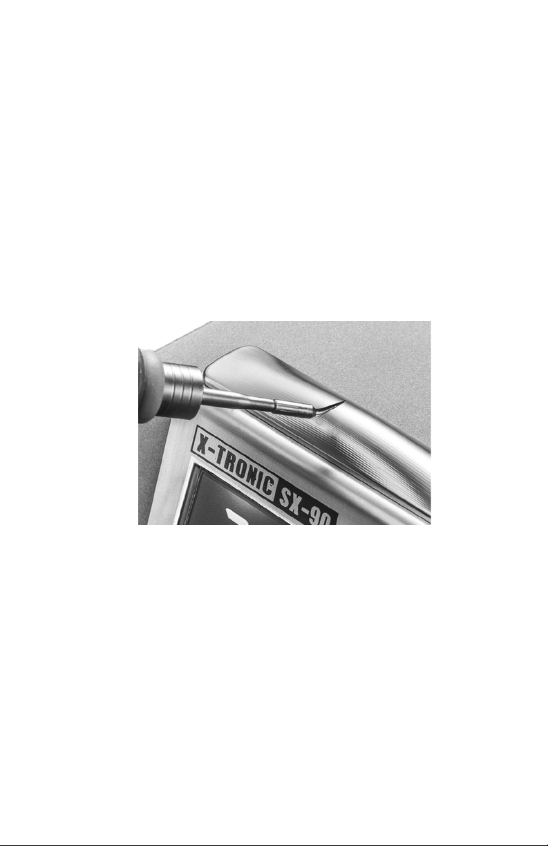
Once the desired temperature has been set and the temperature
of the unit stabilizes, measure the heat at the soldering tip using
a high quality and well calibrated soldering tip tester. If the
temperature shown on the unit’s display does not reflect the
temperature shown on the tester, the unit can be calibrated by
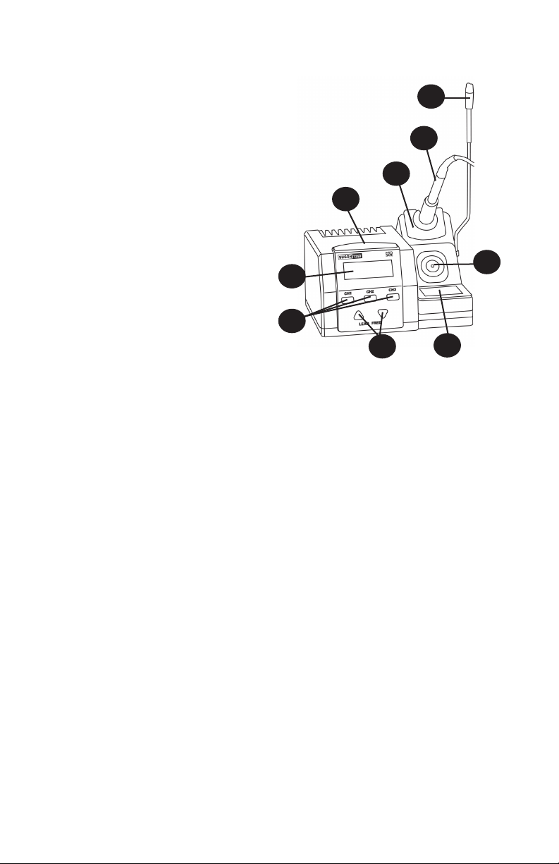
pressing and holding the CH1 and CH3 buttons for 3 seconds.
The Real Temperature will flash and the temperature offset will
show in the bottom right of the display. Press the ▲ and ▼buttons
on the unit to compensate for the degrees of variance. The unit
temperature can be calibrated ±99°. Once the offset has been set,
press the CH2 button to save the setting.
IMPORTANT - PLEASE READ
Infrared (IR) Thermometers should NOT be used to measure the
temperature of the soldering tip as they often provide inaccurate
readings. All IR Thermometers are different and the capability
depends on the Distance to Spot (D:S) ratio of the model being
used. Many IR thermometers have a D:S ratio of 8:1 or 12:1
which means that the thermometer needs to be a distance of 8”
or 12” in order to read a 1” spot size. The tip of a soldering iron is
approximately 2 to 3 mm (.07-.11”), requiring the thermometer to
be 0.8” or 1.2” away from the tip. However, the IR thermometer
also has a minimum distance it needs to be away from the object.
Most IR thermometers will not be capable of measuring such a
small spot size and will provide disappointing calibration results.

- 9 -
MAINTENANCE
SOLDERING TIP CARE
1. For first use, allow the tip to rise to a stable temperature. Clean the
tip on the damp sponge and tin the tip (apply a small amount of
fresh solder to the tip).
2. The soldering iron should be run in the 330°C ~ 360°C range
for regular use, which is the normal temperature range for most
soldering applications. The heating element should last for 6 to 12
months depending on hours of use when the unit is regularly used
within this range.
3. Never hit the soldering iron or tip on anything when trying to
remove excess solder.
4. Do not use extreme temperatures with the soldering iron tips,
doing so will shorten the life span of the tip.
5. Clean the tip before each use, using the brass cleaning sponge for
better temperature stability during use.
6. Always clean and tin the tip after each use. This will aid in the
prevention of oxidation on the tip and help extend its life span.
7. Do not allow the soldering iron or the tips to sit idle at high
temperatures for extended periods of time.
8. Never use a file or other abrasive materials to remove oxidation
from the tips.
9. To remove oxidation, simply flood the tip with fresh solder and wipe
it clean on the damp sponge or copper cleaning pad. This may
need to be repeated several times for badly oxidized tips.
10. To remove the yellowing on the tip shaft (which is perfectly normal,
especially after first use) clean with 90% Isopropyl alcohol.
WARNING: Do NOT use anti-seize or any other lubricant on the tip
retainer or heater of the soldering iron

- 10 -
REPLACING THE FUSE
Fuse
Extra Fuse
Compartment
Fuse Clip
Fuse
Compartment
1. Unplug the power cord from the outlet.
2. Remove the fuse compartment by pressing a flat head screwdriver
into the divot just inside the power socket under the fuse
compartment.
3. The fuse that is in use will be in the fuse clip, the extra fuse is
below it. If the fuse is damaged, replace it with the new fuse.
4. Insert the fuse compartment back into the unit.

- 11 -
TROUBLESHOOTING
ISSUE POSSIBLE SOLUTIONS
Unit does not
have power
• Ensure the power cord is securely attached to both
the unit and the outlet and that the unit is powered
on at the back of the unit.
• Ensure that the outlet is functional.
• Check the fuse in the back of the unit to see if it is in
good working condition. If not, replace fuse.
S-E Error • Ensure the soldering iron is securely plugged into
the back of the unit.
• Ensure the heating element/tip cartridge is securely
seated into the soldering iron.
• The heating element/tip cartridge may need to be
replaced
Tip is not
heating up as
expected
• Ensure the soldering iron is securely plugged into
the back of the unit.
• The soldering tip could be oxidized, it is important
to always tin your tip and keep it clean. See Tip
Maintenance section of manual.
• The heating element/tip cartridge may need to be
replaced
• Unit may need to be calibrated - see Calibration
section of manual

- 12 -
THIS LIMITED WARRANTY GIVES YOU SPECIFIC LEGAL RIGHTS. YOU
MAY ALSO HAVE OTHER RIGHTS, AS THEY VARY FROM STATE TO STATE.
THIS LIMITED WARRANTY CAN ALSO BE FOUND ON OUR WEBSITE AT
WWW.XTRONICUSA.COM/SUPPORT/WARRANTY.
WE WARRANT THAT DURING THE WARRANTY PERIOD, THE PRODUCT
WILL BE FREE FROM DEFECTS IN MATERIALS AND WORKMANSHIP.
WE LIMIT THE DURATION AND REMEDIES OF ALL IMPLIED
WARRANTIES, INCLUDING WITHOUT LIMITATION THE WARRANTIES OF
MERCHANTABILITY AND FITNESS FOR A PARTICULAR PURPOSE TO THE
DURATION OF THIS EXPRESS LIMITED WARRANTY.
SOME STATES HAVE DIFFERENT LIMITATIONS ON HOW LONG AN
IMPLIED WARRANTY LASTS, SO THE ABOVE LIMITATION MAY NOT APPLY
TO YOU.
OUR RESPONSIBILITY FOR DEFECTIVE GOODS IS LIMITED TO REPAIR,
REPLACEMENT OR REFUND AS DESCRIBED BELOW IN THIS WARRANTY
STATEMENT.
WHO MAY USE THIS WARRANTY?
X-Tronic International Inc. located at 2159 Magnum Circle, Lincoln, Nebraska
68522 (“we”) extend this limited warranty only to the consumer who originally
purchased the product in the United States, the District of Columbia or Canada
(“you”). It does not extend to (a) any subsequent owner or other transferee of
the product, (b) any product shipped outside of the United States, the District of
Columbia or Canada, or (c) anyone who may have purchased it from someone
other than X-Tronic International Inc.. Proof of purchase is required for in-
warranty service. We recommend you promptly register this product on our
website (www.XTronicUSA.com) to facilitate verification of the date of the original
purchase. Keep the product manual and your sales receipt together for future
reference.
WHAT DOES THIS WARRANTY COVER?
This limited warranty covers defects in materials and workmanship of the product
for the Warranty Period as defined below. In addition, during the Initial Warranty
Period, this limited warranty also covers defects occurring in the initial shipment
of the product to you.
3-YEAR LIMITED
WARRANTY

- 13 -
WHAT DOES THIS WARRANTY NOT COVER?
This limited warranty during the Warranty Period does not cover any damage due
to: (a) improper use; (b) failure to follow the product instructions or to perform any
preventive maintenance; (c) modifications; (d) unauthorized repair; (e) normal
wear and tear that comes with household use; or (f) external causes such as
accidents, abuse, or other actions or events beyond our reasonable control. It
also does not cover consumable parts.
WHAT IS THE PERIOD OF COVERAGE?
This limited warranty starts on the date of your purchase and lasts for 3 years
(“The Warranty Period”), which shall be divided into two periods: (1) the first
30 days from the date of your purchase (“Initial Warranty Period”); and (2) the
remainder of the 3 year period after the Initial Warranty Period has expired (the
“Remainder Warranty Period”). The Warranty Period is not extended if we repair
or replace the product. We may change the availability of this limited warranty at
our discretion, but any changes will not be retroactive.
WHAT ARE YOUR REMEDIES UNDER THIS WARRANTY?
With respect to any defective product during the Initial Warranty Period, we will,
in our sole discretion either (a) replace such product (or the defective part) free of
charge, or (b) refund the purchase price of such product.
With respect to any defective product during the Remaining Warranty Period,
we will repair such product free of charge and provide a full-service inspection
of your product. You will be responsible for all shipping and handling fees to and
from our facility.
HOW DO YOU OBTAIN WARRANTY SERVICE?
To obtain warranty service, you must call 844-861-4762 or email us at Info@
XTronicUSA.com during the Warranty Period to open a service request. Proof of
purchase will be required to open a service request.
LIMITATION OF LIABILITY
THE REMEDIES DESCRIBED ABOVE ARE YOUR SOLE AND EXCLUSIVE
REMEDIES AND OUR ENTIRE LIABILITY FOR ANY BREACH OF THIS
LIMITED WARRANTY. OUR LIABILITY SHALL UNDER NO CIRCUMSTANCES
EXCEED THE ACTUAL AMOUNT PAID BY YOU FOR THE DEFECTIVE
PRODUCT, NOR SHALL WE UNDER ANY CIRCUMSTANCES BE LIABLE FOR
ANY CONSEQUENTIAL, INCIDENTAL, SPECIAL OR PUNITIVE DAMAGES OR
LOSSES, WHETHER DIRECT OR INDIRECT.
SOME STATES HAVE DIFFERENT LIMITATIONS OF LIABILITY AND
EXCLUSIONS, SO THE ABOVE LIMITATION OR EXCLUSION MAY NOT
APPLY TO YOU.

QUESTIONS, PROBLEMS
OR COMPLIMENTS?
Thank You for purchasing this
X-Tronic International Product!
We are grateful for your business!
All of our X-Tronic International Products are inspected
then sealed with our NEW Product Seal prior to
shipment. Our goal is to ensure Quality, Completeness,
and Satisfaction for your order.
For Any Questions, Problems, or
Compliments please call or email us.
If you would like to shop for other X-Tronic International Products
Please visit our website
www.XTronicUSA.com
Toll Free: 844-861-4762
Info@XTronicUSA.com
Our Business Hours are:
Monday - Thursday: 8am - 4pm CST
Friday: 8am - Noon CST
This manual suits for next models
1
Table of contents
Other XTRONIC Soldering Gun manuals

XTRONIC
XTRONIC 4008-PRO-X User manual

XTRONIC
XTRONIC 3020-XTS User manual

XTRONIC
XTRONIC 3050-PRO-X User manual

XTRONIC
XTRONIC 9070-XR3 User manual

XTRONIC
XTRONIC PX-70 User manual

XTRONIC
XTRONIC 6040-PRO-X User manual

XTRONIC
XTRONIC 3090-PRO-X User manual

XTRONIC
XTRONIC 3060-XTS User manual

XTRONIC
XTRONIC 5040-XR3 User manual

XTRONIC
XTRONIC 4010-PRO-X User manual