manuals.online logo
Brands
  1. Home
  2. •
  3. Brands
  4. •
  5. Xytronic
  6. •
  7. Soldering Gun
  8. •
  9. Xytronic IR860 User manual

Xytronic IR860 User manual

IR860
SMD/BGA Rework System
Operating Manual
„ Thank you for choosing XYTRONIC IR Solderlight. This appliance is specially designed
for SMD/BGA rework and also very convenient for re-balling smaller BGA components.
When used in conjunction with our Infra-Red Preheater, the system will achieve
remarkable improvements in quality and efficiency of SMD/BGA rework operations.
Please read this manual carefully to maximize the advantages of using your new
SMD/BGA rework system and keep this manual readily accessible for reference.
C a t a l o g u e
●Introduction (Warning & Caution)……………………………….P. 3-4
●Installation and Specifications ………..……………………..P. 5-6
●Features…….……………………………..….…….…………….P. 7-9
●Principle of operation and Preparation.…………………….…..P.9-13
●Soldering ………………………………………………………...P. 15
●Desoldering………………………………………………………P. 15
●Q & A…………………………..………………………..….…P. 16-17
INTRODUCTION
:【WARNING 】and【CAUTION 】 【ELECTRICAL SHCOK 】
Warning and caution are positioned at critical points in the manual to
draw the user’s attention to significant safety concerns. Be sure to comply
with the following warnings and cautions for your safety.
11. Ensure the voltage rating of the unit and your power supply are identical prior to
use.
22. Check carefully of any damage during transportation.
33. Put the products on a safe and stable working table. Table surface should be
consisted of fire and heat resistant material due to the unit can reach very high temperature
and potentially dangerous.
44. During the operation, the heater is extremely hot, and will cause serious burns if
contacted exposed skin. Use gloves and/or any heat resistant tools to pick up the PCB
assembly to eliminate the possibility of burns.
55. Do not use the product near combustible gases or flammable materials.
66. Turn the power switch OFF and allow the heater to cool before checking or
replacing heater and other parts, or prior to storing the unit.
77. Keep the appliance clean especially the quartz heater. This may be used with a
damp cloth using small amount of liquid detergent. Never submerse the unit in liquid or
allow any liquid to enter the station. Never use any solvent to clean the case.
88. Quartz heater is fragile, be slightly moving the station if necessary.
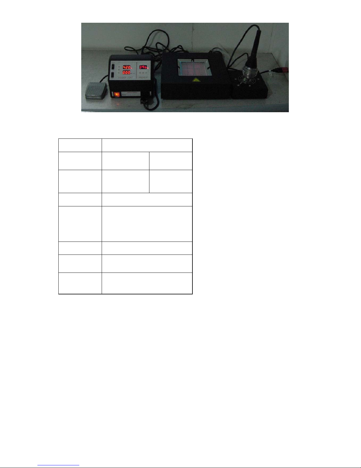
99. This unit is designed for SMD rework, BGA re-balling and pre-heating PCB
assembly and should not be used for any other purpose without first consulting the
manufacturer or its authorized agent.
10 10. Keep the unit out of the reach of children. Young Children should be supervised
to ensure that they do not play with the appliance.
To prevent electrical shock, be sure to take the following precautions:
1Make sure the unit is grounded. Always connect power to a grounded receptacle.
2Do not pressure the AC power cord. Be sure the work area is well ventilated.
3Do not bump, hit, pour water/liquids or otherwise subject the heating surface to
physical shock. This may damage the quartz heater.
4To isolate the equipment from the mains before commencing repairs or making any
maintenance to avoid electric shock. This may result in Death or serious injury.
5Do not expose the unit to moisture nor use the unit with wet hands.
6Turn the power switch off and remove the AC power cord by pulling the plug (not
the cable) when the unit will remain unused for a longer period of time.
7Do not modify the unit.
Warnings
ٛThis system is designed to be used for soldering/desoldering SMDs and should
not be used for any other purpose without consulting manufacturer or its agents.
ٛThe IR hand tool is designed for intermitted use only. It is not designed to be
used continuously without being allowed to cool. It should be used a maximum of 5 minutes
before cooling. After using the IR hand tool, ensure that it is placed back in its cooling stand
to cool down between rework operations. Also, do not switch the IR Hand tool on while it is
in the cooling stand. Fail to comply with there instructions may result in damage to the
IR hand tool or the cooling stand.
ٛDo not aim the IR hand tool at your eyes. Do not allow the IR spot from the IR
hand tool (either directly or via mirror) to shine into the eyes as serious eye damage may
occur.
ٛThe system can produce a lot of heat. Do not allow the IR spot from the IR hand
tool or IR from the PCB pre-heater, to contact exposed skin as burning may occur. To
eliminate the possibility of burns, allow time for the equipment to cool before commencing
maintenance.
ٛDeath or serious injury may result from electric shock. It is therefore essential to
isolate the equipment from the mains before commencing repairs.
ٛDo not allow the spillage of any liquid to fall on the quartz emitter (pre-heater)
as damage may result. Due to the use of glass optical components, the IR hand tool should
be handled with reasonable care.
Installation
The equipment must be sited on a firm surface at least 1.2M x 0.75M and at a height to suit
the operator. The location should be chosen to suit the flow of work.
Place the controllers on the left or right of the main system and arrange the system as in the
picture (A) as below. The immediate areas must be free from draughts that may reduce the
heating efficiency. A mains electricity supply, free from R.F. interference, other noise,
glitter etc. must be readily available.
(A) Standard package for IR860 SMD/BGA rework system
IR810 Infra red SMD/BGA rework station
Specifications for IR860
SOLDERLIGHT CONTROL
Power rating 220-240Vac
50Hz
100-120Vac
60Hz
Fuse T2A (Slow
type)
T3.15A
(Slow type)
Output 15Vac 150W
IR Lamp
temp. range 45℃-450℃ (113℉-842℉)
Time setting 0 – 900sec
Size (W*H*
D) 170 x 100 x 200mm
Net weight 3.3Kg
Specifications for Preheater
Preheater
Rating 230Vac 115Vac
Fuse (Delay type) T5A T10A
Output 650W
Temperature range 30℃-350℃ (86℉
-662℉)
Controller
Dimensions
170x100x200mm
(W x H x D)
Weight (w/o AC
power cord) 1.4Kg
Pre-heater
Dimensions
280x90x257mm (W
x H x D)
Weight (w/o AC
power cord) 2.8Kg
Features of IR860 Front panel
ٛ1. Timer switch
ٛ2. Power Switch for Solderlight
ٛ3. “Down” key - Time counting & temperature decrease
ٛ4. “Up” key - Time counting & temperature increase
ٛ5.“SOLDER LIGHT” - Temperature display (3 segment) IR hand tool intensity
(power)
ٛ6. Celsius (℃) temperature light for Solderlight
ٛ7. Fahrenheit (℉) temperature light for Solderlight
ٛ8.“RESET”- Offset frontward counting
ٛ9. “TIMER”- Time counting display (3 segment)
Process timer
ٛ10. “ALARM”- Time setting
ٛ11. Temperature up pad (increase numerals) for PREHEAT
ٛ12. Temperature down pad (decrease numerals) for PREHEAT
ٛ13. MODEL: Temperature offset pad
ٛ14. Fahrenheit (℉) temperature light for PREHEAT
ٛ15. Celsius (℃) temperature light for PREHEAT
ٛ16. Temperature setting display (3 segment)
IR810 Back panel
ٛ1. Foot switch socket (4 pin)
ٛ2. DC12V Cooling fan socket (3 pin)
ٛ3..Output to PREHEATER
ٛ4. Fuse Holder Solderlight connector
ٛ5. AC power inlet
Infra red pre-heater back panel
1Quartz heater gets faster heat-up time.
2The efficient pre-heat height is 45mm from quartz surface to the bottom of the PCB
assembly.
3The temperature of back heater setting at 220℃ can get apparent preheating (75%
energy is provided by the back heater and 25% of the energy provided by the top heater) get
efficient preheating performance and prevent the bent of bigger PCB and/or damage the
components just heating from the top heater.
Principle of Operation
Overview
The principle of operation of IR rework system is that whilst being heated from above and
below, a single SMD is subjected to similar temperature/time profile during rework as it
experiences during reflow in the original production process.
À Temperature setting range:45℃~450℃(113℉~842
℉) Original temperature setting: 45℃ (113℉) À
Timer setting range: 0 - 900sec
Time counting: Forward counting starts from 000S (UP/DOWN switch flip to “UP”
position). Backward counting commences from 015S (UP/DOWN switch to “DOWN”
position).
IR hand tool operation:
¢Flip the “IR/TIMER” switch on to the IR position.
¢Reset IR Lamp temperature: By pressing “▲” or “▼” Temperature forward counting: If
pressing “▲” key one time, the digital will be increased “1” numeral. If pressing “▲” key
over 2 seconds then the digital numerals will be forwarded continuously till the
temperature you set and then depressing the “▲” key off.
Temperature backward counting: If pressing “▼” key one time the digital will be
decreased “1” numeral. If pressing “▼” key over 2 seconds then the digital numerals
will be down continuously till the temperature you set and then depressing the “▼”
key off.
¢Step “footswitch” the IR lamp commence to warm up, release the “footswitch”, IR lamp
will be stop operating.
IR lamp operating with positive numeral module
¢Flip the “TIMER/IR” switch to “TIMER” position and “UP/DOWN” switch to “UP”
position, then IR lamp will be operating with positive numeral digit. (See picture on
right side)
¢Please note: The feature of positive counting is to calculate the IR lamp heat up time and
it is not able to be adjusted. Time counting can be calculated automatically by stepping
“footswitch”.
À Press the “RESET” then the positive counting will be off and numeral shown
“0”. ¢If released the footswitch then positive numeral time counting will be
stopped, step again then the timing will be calculated continuously. ¢The IR
lamp and positive numeral counter will be commenced counting when
footswitch being stepped. The vise-versa.
IR lamp operating with negative numeral module
¢Flip the “TIMER/IR” switch to “TIMER” position and “UP/DOWN”
switch to “DOWN” position, then IR lamp will be operating with
inverse counting. (See picture on right side)
¢Please note: The feature of positive counting is to calculate the IR lamp
heat up time and it is not able to be adjusted. Time can be calculated
automatically by stepping “footswitch”.
¢Press the “RESET” then the negative counting will be off and numeral
shown “0”.
¢If released the footswitch then positive numeral counting will be stopped, step again then
the timing will be calculated continuously.
¢The IR lamp and positive numeral counter will be commenced counting when footswitch
being stepped, the vise-versa.
¢To check a reflow time of new component, there are two ways to get the negative numeral
counting, one by using positive numeral counting data converse to negative numeral
counting and the second way by adjusting
OPERATION FOR PREHEATER
1Flip the “POWER” switch to “ OFF ” position.
2Insert the female plug into the AC power receptacle (Mains inlet) on the back of the
unit.
3Insert the connector/receptacle cord from the back output of controller to back of
pre-heater inlet.
4Plug the AC power cord and flip the mains illuminated switch to the “ ON ” position.
5The PREHEATER is ready to use.
Temperature parameter value setting
Temperature setting range: 30℃~350℃ (86℉~662℉)
Temperature compensation range: +99℃~ -99℃ (+99℉ ~ -99℉)
Preset temperature: 30℃ (86℉)
Temperature adjustment: “00” or “-00”
À Pre-heater temperature setting: By pressing “▲” or “▼” pad to increase or
decrease the temperature. Would suggest set temperature at “220℃ (430℉approx.) for
better performance.
Temperature forward counting: If pressing “▲” pad one time, the digital will be
increased “1” numeral. If continuous pressing “▲” pad then the digital numerals will
be forwarded till the temperature you would set or adjust and then depressing the “▲”
pad off.
Temperature backward counting: If pressing “▼” pad one time the digital will be
decreased “1” numeral. If continuous pressing “▼” pad then the digital numerals will
be backward till the temperature you would set or adjust and then depressing the “▼”
pad off.
1. Check actual temperature compensation value:
Press “MODEL” pad until digital display show “- - -“, then release the “MODEL” pad,
the display will show the actual temperature compensation value automatically after 4
seconds. After 2 seconds the display will be back to preset temperature.
2. Actual temperature adjustment: Press “MODEL” pad until digital display show “- -
-“ ,then press the “MODEL” pad again within 4 seconds, the display will show the actual
temperature compensation value automatically and twinkling. Now it is ready to adjust by
using “▲”and “▼” pads. Press “▲” pad the temperature will be up and press “▼” pad
the temperature will be down. If there is no need to adjust the temperature, after 2 sec. the
display will become normal situation. For example: Assume the temperature set at 200℃ and
actual temperature being measured 190℃, then the temperature to be needed to adjust +10℃
and the parameter value shows “00 or -00"then temperature compensation value is“10"[00
+ 10=( increase 10℃)]. If the parameter value shows -20 then temperature compensation value
is 10 (-20+10=10℃). If the parameter value shows 20 then the compensation value is 30 [20
(20)+10 (10)=30 (30℃)].
CAUTION:To avoid burning your skin, do not touch the heater or PCB directly,
please use clips or tweezers for pick up.
CAUTION:Do not allow water/liquids/solvents to touch the heater surface to avoid temperature drop
cracks while the unit is still hot. Such cracks can lead to electrical shorts or failure of the
heater.
CAUTION:Do not touch the PCB holder to avoid burning your skin during preheat!
Preparation
The procedure while preparing to rework SMT/BGA components as follows:
ٛSwitch on and warm up.
ٛSet ‘control settings’ required for PCB/component
ٛSort tools and fluxes required.
Switch on and warm up The following simple procedure will warm the system up
ٛSwitch on the IR 810 controller
● Set control settings
- Set IR hand tool power setting between 220-380℃ (normal = 240℃)
-Set Pre-heater power setting between 200-290℃ (normal = 240℃)
ٛAllow system to warm up – switch pre-heater on and wait 5 minutes.
Tools and fluxes required
The following are required for use in soldering/desoldering operations:
ٛSMT Tweezers, fine tipped
ٛFlux dispenser bottle
ٛLow solids and gel/paste flux
When using IR 860 rework system it is vital to use correct materials for successful rework.
We use two types, a low solids liquid flux for general rework and a gel/paste flux for
QFP/DGA rework. The above tools/fluxes are available as kits.
Temperature Profile
In operation the component is first put through a preheat stage, followed by a reflow stage.
The system is designed for rework single/double side and mixed technology PCB. The top
heat is derived from a 150W short wave IR lamp focused through a reflective chamber
system. The bottom heater delivers a maximum of 650W medium wave IR.
In normal use, approximately 25% of the energy is proved by the top heater, and 75% of the
energy is provided by the back heater (pre-heater). Figure below shows how the energy is
applied to a component.
Soldering
ٛPREPARATION - Place PCB in the PCB holder, positioning the component site to
be reworked over the center of the PCB pre-heater. For BGAs, apply a very small amount of
gel flux (approx. 0.1 - 0.15mm) thickness). Place and align component. ( note – depending
on the application, y0ou may be required to apply solder paste to the PCB before placing
component.)
ٛ(A) PREHEAT – the fluxed component/PCB to approximately 120℃(as measured
by the IR sensor).
ٛ(B) REFLOW – use the IR hand tool (operated by pressing the footswitch) for the
reflow phase to heat the component up to reflow temperature (200-225℃). It is not so easy
to measure temperature during the reflow phase so therefore we use the timer on the IR 810
controller to limit the reflow phase time (normally 30-45 seconds for a small PCB).
ٛ(C) SOAK – for a short period to soak (about 10 seconds) the component allowing
the joints to fully bond.
ٛ(D) COOL – allow the component to cool to below 180℃before moving the PCB.
Desoldering
ٛPREPARATION - Place PCB in the PCB holder, positioning the component site to
be reworked over the center of the PCB pre-heater. Apply a very small amount of flux
under/around the component.
ٛ(A) PREHEAT – the fluxed component/PCB to approximately 120℃(as measured
by the IR sensor).
ٛ(B) REFLOW – use the IR hand tool (operated by pressing the footswitch) for the
reflow phase to heat the component up to reflow temperature (200-225℃). It is not so easy
to measure temperature during the reflow phase so therefore we use the timer on the IR810
controller to limit the reflow phase time (normally 30-45 seconds for a small PCB).
ٛ(C) SOAK – for a short period to soak (about 10 seconds) the component allowing
the joints to fully bond.
ٛ(D) COOL – allow the component to cool to below 180℃before moving the PCB.
Aftercare
ٛClean flux residue off PCB if necessary
ٛCheck solder joints
ٛTest
Q & A
What Top Heat setting should you use ?
Between 220-380℃. Normal setting is 240℃
What’s the working distance of the IR Hand tool and how do I move it for rework?
Approximately 5 – 10 mm when reworking and move up to 30mm when removing
Component – move the hand tool in a scanning motion to heat leads, taking about one
second for each scan of the component.
What pre-heater setting should I use?
Between 200-290℃. Normal setting is 240℃
How long do I preheat the PCB?
Always preheat the PCB (up to 120℃or between 45 – 90 seconds) to allow the heat to
conduct through to the component before introducing the Top Heat. With the 700W
pre-heater the top of a small PCB will reach 120℃in approximately 45 – 90 seconds.
Larger PCBs will take longer to pre-heat. To check the PCB/component temperature, use the
hand-held IR temperature sensor to ‘look’ down at the PCB/component from about 60mm
away and at about 45° angle.
How long does it take to reach reflow temperature?
After preheating the PCB up to 120℃, it should normally take about 30 – 45 seconds of
heating with the IR hand tool to reach reflow (200-220℃). It is not so easy to measure
temperature during the reflow phase so therefore we use the electronic process timer to warn
us when the reflow phase time is over.
TROUBLE SHOOTING
WARNING:
1Unless otherwise stipulated, carry out these procedures with the power switch OFF
and the power UNPLUGGED before the trouble is cleared.
2If the unit is damaged, it should be repaired by the manufacturer or its authorized
repairing centers to preclude damage to either the unit or injury to personnel.
3Be sure the unit has been cooled to room temperature before beginning work.
Item Problem Remedy
1. No Power when
Power switch
“ON”
a. Check the AC power
cord and receptacle. b.
Mains switch no good. c.
Fuse blown out.
1. Re-insert the plug. 2. Replace
the switch. 3. Investigate why the
fuse blew then replace a new fuse.
(If the cause can not be
determined, just replace the fuse.
If the fuse blows again, send the
unit to repair.)
2. Heater no
temperature
a. Quartz heater open. b.
Check connector /
receptacle cord
connecting in good
condition or not c.
Check the controller
PCB assembly failed or
not d. Check the display
PCB assembly
1. Replace the quartz heater
assembly. 2. Re-insert the cord. 3.
Replace a new PCB assembly 4.
Replace a new display PCB
assembly
3.When mains
switch is in “ON”
position but
display not shown
a. Check the AC power
cord inlet. b. Check the
AC power transformer
output is AC12V for
IR810 and AC9V for IR
610. c. Check the
controller PCB has
DC5V output d. Display
burnt
1. Reconnect. 2. Replace a new
transformer if burnt. 3. Replace
the PCB assembly if failed. 4.
Replace the display PCB
assembly.
4. IR Lamp not
light
a. Check the IR lamp b.
Check the 15A fuse on
IR810 c. Check the AC
power transformer has
AC15V output. d. Forget
to step foot switch
1. Replace the IR lamp if burnt. 2.
Investigate why the fuse blew
then replace a new fuse (If the
cause can not be determined, just
replace the fuse. If the fuse blows
again, send the unit to repair.) 3.
Replace a new transformer if
burnt. 4. Step foot switch. Replace
the foot switch if no function.
5. Cooling fan no
function
a. Check the cooling fan
b. Check back panel has
DC12V output.
1. Replace the cooling fan if
burnt. 2. Replace control board if
no output. 3. Re-inset the cord, if
there is output.
6. IR lamp keep
light
a. The foot switch short
b. The receptacle and
connector short. c. Keep
light on after main
switch off and re-on.
1. Check the foot switch if short.
2. Re-solder it if short. 3. Replace
the control or display PCB.

Other Xytronic Soldering Gun manuals

Xytronic LF- 8800 User manual

Xytronic

Xytronic LF- 8800 User manual

Xytronic LF-1600 User manual

Xytronic

Xytronic LF-1600 User manual

Xytronic LF-1700 User manual

Xytronic

Xytronic LF-1700 User manual

Xytronic LF-3500 User manual

Xytronic

Xytronic LF-3500 User manual

Xytronic LF-3200 User manual

Xytronic

Xytronic LF-3200 User manual

Xytronic LF-853D User manual

Xytronic

Xytronic LF-853D User manual

Xytronic LF-2000 User manual

Xytronic

Xytronic LF-2000 User manual

Xytronic LF-855D User manual

Xytronic

Xytronic LF-855D User manual

Xytronic LF-988D+ User manual

Xytronic

Xytronic LF-988D+ User manual

Xytronic LF-8000 User manual

Xytronic

Xytronic LF-8000 User manual

Xytronic LF-1000 User manual

Xytronic

Xytronic LF-1000 User manual

Xytronic T 1976 User manual

Xytronic

Xytronic T 1976 User manual

Xytronic LF-1680 User manual

Xytronic

Xytronic LF-1680 User manual

Xytronic LF-389D User manual

Xytronic

Xytronic LF-389D User manual

Popular Soldering Gun manuals by other brands

Rebel LUT0043 user manual

Rebel

Rebel LUT0043 user manual

Weller LR 21 operating instructions

Weller

Weller LR 21 operating instructions

Duratool D00674 quick start guide

Duratool

Duratool D00674 quick start guide

Weller WXD 2 operating instructions

Weller

Weller WXD 2 operating instructions

jbc SF manual

jbc

jbc SF manual

Draper SG100 instructions

Draper

Draper SG100 instructions

aoyue 2738 instruction manual

aoyue

aoyue 2738 instruction manual

ersa DIGITAL 2000 A operating instructions

ersa

ersa DIGITAL 2000 A operating instructions

Duratool D03325 quick start guide

Duratool

Duratool D03325 quick start guide

Edsyn 981C-230 instruction manual

Edsyn

Edsyn 981C-230 instruction manual

jbc PHXLE-K instruction manual

jbc

jbc PHXLE-K instruction manual

Weller WLC200 operating instructions

Weller

Weller WLC200 operating instructions

Velleman VTSSC71 user manual

Velleman

Velleman VTSSC71 user manual

jbc JT-SD user manual

jbc

jbc JT-SD user manual

SUN EAST PEAK-350 user manual

SUN EAST

SUN EAST PEAK-350 user manual

Cooper Tools Weller WSM 1 operating instructions

Cooper Tools

Cooper Tools Weller WSM 1 operating instructions

Velleman HRJA100 user manual

Velleman

Velleman HRJA100 user manual

HSGM ENGEL 60 S operating instructions

HSGM

HSGM ENGEL 60 S operating instructions

manuals.online logo
manuals.online logoBrands
  • About & Mission
  • Contact us
  • Privacy Policy
  • Terms and Conditions

Copyright 2025 Manuals.Online. All Rights Reserved.