Xytronic LF-8000 User manual

Instruction Manual
for
LF-8000 Soldering/Desoldering Station
(Forleadfreeoperations)
Congratulations on selecting Xytronic’s – the best solution for all your soldering/
desoldering equipment needs especially for the lead free soldering works! We believe
you will be more than satisfied with the many features and the versatility of your new
soldering/desoldering station. Xytronic’s products have been serving the electronics
industry for over 25 years and with its many special features have proven to be the
ultimate in a soldering/desoldering instrument. Please carefully read the instruction
manual to maximize the advantages of using your new soldering/desoldering station.
IMPORTANT: The LF-8000 operates basically the same as the standard 988D but
with the high power 32V/100W for soldering/desoldering irons which are specially
designed for lead-free soldering/desoldering works to meet RoHS requirement.
Please refer the attached 988/988D instruction manual for desoldering operations.

1
KEY FEATURES
EXTERNAL CALIBRATION PORT: The LF-8000 has two calibration ports on the
front panel for both soldering/desoldering for quick and convenient precision
temperature adjustments.
DELAYED SUCTION: To eliminate the problem of solder clogging up the tip, a
delayed switch feature has been incorporated for the unit that allows the pump to
continue sucking for 1.5 seconds after the actuator switch is released.
*LIGHTWEIGHT SOLDERING IRON: Ergonomic mini handle that stays cool and
prevents operator fatigue.
*OPTIONAL TWEEZERS: This additional feature is specially designed for SMD
chips, SOT, Flat pack ICs’etc. rework. Tweezers TWZ100 is equipped with 32V/50W
x 2 conventional nichrome heater, which can be interchangeable with soldering iron
210ESD as an option.
*ENERGY SAVER: After the station has been idle for more than 15 minutes, this new
feature will automatically knick in. When the “Pause” LED is lit, the energy saver
feature has engaged, decreasing tip temperature by 1/3 which cuts power consumption
and extends tip life.
* CELSIUS/FAHRENHEIT SWITCH: To address the global market place, a
convenient switch has been incorporated to easily convert from one common measure
to another.
PRODUCT DESCRIPTION
LF-8000 operates basically the same as the standard digital readout 988D but with the
high power 32V/100W soldering and desoldering irons which are specially designed
for lead-free soldering works to meet RoHS requirement.
This unit built in a self-contained, oil free, maintenance free, and quiet running
vacuum pump which is electronically controlled and will not overload with
continuous use, eliminating the need for additional shop air. The vacuum pump
provides up to 50cm/Hg (20in/Hg) suction power, activated by a push button
switching circuit located on the desoldering iron housing. Internal solder collector in
handpiece is quickly and easily removed for cleaning. The inside mesh aluminum
cooling strip has better solder chip adherence. Also the ventilation slots makes for a

2
cooler handle, improving operator comfort.
LF-8000 incorporates electronic circuitry which enables the user to fine tune
soldering tip temperature from 200℃(392℉) through 450℃(842℉) and
desoldering tip temperature from 300℃(572℉) through 450℃(842℉) without
changing tips or heating elements. Both soldering and desoldering irons are equipped
with a precision would nichrome heating elements, both offer 32V/100W output.Also
there is an optional fume extraction kit can be equipped easily on the soldering iron.
The temperature is maintained within +/-3℃(+/-6℉) of its operating temperature by
a thermocouple sensor to ensure maximum temperature as close to the working
surface of the tip as possible. This results in both a rapid heat up, fast recovery and
exacting temperature control with minimal overshoot. The ergonomic and slender
soldering iron design with a comfortable silicone rubber grip prevents operator
fatigue.
The revolutionary “Zero Voltage” electronic switching design also protects voltage
and current sensitive components (CMOS devices etc.) against damaging current and
transient voltage spikes commonly produced by less efficient, mechanically switched
stations. The power unit is isolated from the A.C. line by a transformer and allows
32Vac for soldering and desoldering to drive the heating elements. Both soldering and
desoldering are constructed with an individual calibration port locating under the
digital display on the face of the unit for quick and convenient precision temperature
adjustments.
The new LF-8000 has been developed to meet the present and future needs of the
electronic production industry and is ideal for use at any AC outlet. Engineered to
meet the demanding needs of the hobbyist, service & repair technician as well as
production people alike.
WORKING TEMPERATURE
To meet RoHS requirements, the common 60/40 lead solder alloys are not allowed in
the production process. Lead free solder alloys require a working temperature of 30℃
(54℉) higher than previous generation electrical soldering. The working temperature
of solder is detailed below and can vary from manufacture to manufacture.
Meltingpoint 220℃(428℉)

3
Normal operation 300-360℃(572-680℉)
Production line operation 360-410℃(680-770℉)
When the soldering iron’s working temperature is set within the parameters suitable
for the type of soldering being used, a good joint assured. Too low of a temperature
will slow the rate of solder flow while a high temperature setting might burn the flux
in the solder and emit a heavy, white smoke resulting in a dry joint or permanent
damage to the printed circuit board (P.C.B) and may also shorten tip life.
IMPORTANT: The temperature above 410℃(770℉) is not recommended for
normal soldering functions, but can be used for short periods of time when high
temperatures are required.
OPERATING INSTURCTIONS
OPERATING PROCEDUCRES FOR LF-8000:
1. Ensure that the working voltage matches your power supply before beginning use.
2. Check carefully for any damage during transportation.
3. This unit contains:
A: DIA80: Desoldering iron assembly with tip.
B: 210ESD: Soldering iron assembly with tip.
C: Two iron holders with tip cleaners for both soldering and desoldering.
D: AC Power cord with plug.
Accessories included:
a. One cleaning brush
b. One cooling strip
c. One 0.7∮ probe
d. 4pcs of filters
4. Optional parts:
A) TWZ100: 32V/100W Tweezers can be interchangeable with 210ESD soldering
iron.
B) Fume extraction kit: For soldering iron only
C) HAP80: 32V/80W Hot air blow pencil can be interchangeable with DIA80.
OPERATING PROCEDUCRES
1. Ensure that the base unit’s power switch is in the ‘OFF” position.
2. Plug in “Solder and Desolder” wands, connect “Vacuum tube” to “VAC”.
3. Connect AC power cord to mains “In-Let”.

4
4. Set “Temperature control knobs” to “MIN”.
5. Switch “Mains power switch” to “ON” position, then switch both “SOLDER &
DESOLDER” switches to “ON” position, both pilot lamps will be “ON”.
6. Tin the surface of both soldering and desoldering tips by applying a new covering
of solder to protect it.
7. Set both “Temperature control knobs” to the desired temperature about 3 minutes
after being warmed. The unit will be ready for use once it reaches preset
temperature – indicated by the pilot light going off.
8. A slide switch below the digital display allows the operator to toggle between
Fahrenheit and Celsius temperature readout.
9. You can preset the temperature setting by pushing the slide switch to “SET”
position. Use the temperature controlled knob to set the desired temperature.
Then slide the switch to “READ”. The temperature will then maintain a +/-3℃
(+/-5℉) with the display showing actual tip temperature.
PLEASE NOTE:
1. Both soldering, desoldering irons can be used at same time.
2. If LF-8000 is idle for more than 15 minutes, an energy saving feature will
automatically engage (evident by the green “PUASE” indicator light), reducing
idle temperature by 1/3 and extending your tip life.Activating he red suction
button on the desolder handle will disengage the power saving feature and the unit
will immediately ramp up to the preset temperature.
CUATION: Do not touch any of the irons at any time while the unit is on or while it’s
cooling as they will still be hot.
NEW FEATURE FOR LF-8000
There is a calibration port on the front panel for both soldering and desoldering under
the digital readout. This calibration is to be used in conjunction with an external
thermometer. Place the tip on the thermometer, if the actual tip temperature reads
higher or lower than the display on the thermometer temperature, then using a
2mm precision screwdriver to calibrate the temperature. Both soldering and
desoldering sides if turning clockwise that the actual tip temperature will be up
(+). Counter clockwise will let the tip temperature down (-).

DRAWING OF LF-8000
IMPORTANT
DESOLDERING
1. Only activate the vacuum after the solder has completely melted. Melting is
accomplished by moving the hot tip around the lead leaving visible melted
solder on the component side of the P. C. B.
See Fig. 1 & 2.
2. Release the vacuum switch only alter the solder on the tip has been removed,
otherwise the tip may clog.
3. Add solder to the joint of the component and allow the solder to melt completely
for improved desoldering.
4. Remove the solder collector and clean it after no more than 200 applications.
However, daily cleaning is strongly recommended.
5. Replace the cotton pad in the solder collector and the in-line filter when they
begin to turn yellow.
6. If there is insufficient vacuum, use the spring wire included to clean the tip and
also check he in-line filters.
7. Be sure that all filters are in place during operation or damage to the vacuum
5

6
pump may occur.
8. Follow the steps outlined in the OPERATIOING PROCEDURE section of this
manual if a new tip is to be installed.
SOLDERING
1. Temperature above 410℃(770℉) should not be used for normal soldering
purposes. However, irons can be used for short periods of time when occasion
demands, but should be used with caution.
2. See the OPERATING PROCEDURES section of this manual for tip replacement.
COMMON CAUSES FOR TIPFAILURES
1. Tip temperatures higher than 410℃(770℉).
2. The tip working surfaces are not tinned while the iron idling.
3. Lack of flux in soldering, wicking, repair, and touch-up operations.
4. Wiping the tip on a high sulfur content, dirty or dry sponge.
5. Contact with organic substances such as plastic, resin, silicone, grease and other
chemicals.
6. Impurities in the solder and/or low tin content.
CARE OF TIPS
CAUTION: The soldering, desoldering irons can reach very high temperature. Be
sure to turn the unit off prior to carrying out any maintenance or trouble shooting
steps listed below!
IMPORATNT:
Remove the tip and clean after each moderate to heavy use or daily for light usage.
Remove any loose build up in the tip retaining assembly to prevent tip freezing.
Both solder, desolder tips supplied are iron clad copper and if used properly should
maintain optimum life.
1. Always tin the tip before returning it to the holder, turning off the station, or storing
it for long periods of time. Wipe the tip on a wet sponge or our tip cleaner 460 prior
to use.
2. Keeping the iron set at high temperatures (more than 400℃or 750℉) will shorten
tip life.
3. Do not use excessive pressure on the tip or rub the joint with the tip while
soldering and/or desoldering, it does not improve the heat transfer and may
damage the tip.
4. Never clean the tip with a file or abrasive materials.

7
5. Do not use fluxes which contain chloride or acid. Use only rosin or resin activated
fluxes.
6. If an oxide film forms, it can be removed by careful buffing with 600-800 grit
emery cloth, isopropyl alcohol or equivalent and then the tinned areas with
rosin-core solder after the resin-core has melted.
NEW TIPS
Applying the following steps give the tip optimum life.
1. Set both temperature to min. then turn the main power switch to the “ON”
position.
2. Set soldering tip temperature to 250℃(500℉approx.) and desoldering tip
temperature to min. Coat the tinned surfaces with rosin-core solder after reaching
250℃.
3. Set to the desired temperature about 3 minutes after being warmed that the station
will be ready for sue once it reaches preset temperature.
IMPORTANT: Remove and clean the tip daily. If a new tip is installed, remove any
loose build up ion the tip and barrel assembly, otherwise the tip may fuse to the
heating element or retaining barrel.
METHOD TO CHECK FOR LOSS OF SUCTION
The following procedures should be used on LF-8000 to check whether loss of
suction is due to the tip, solder collector, tube or in-line filter.
CAUTION: THE DESOLDER SWITCH MUST BE “OFF” AND ALLOW THE
IRON TO COLL BEFORE ATTEMPTING THE FOLLOWING PROCEDURES:
1. Disconnect vacuum tube form the fitting on the front panel, place finger over the
hole of the fitting, depress vacuum switch and you should have a strong vacuum.
If not, send back to your nearest service center for pump repair.
2. Disconnect the inline filter from the iron assembly, depress vacuum switch,
replace filling of the in-line filter if there is little vacuum pressure or the filters are
discolored.
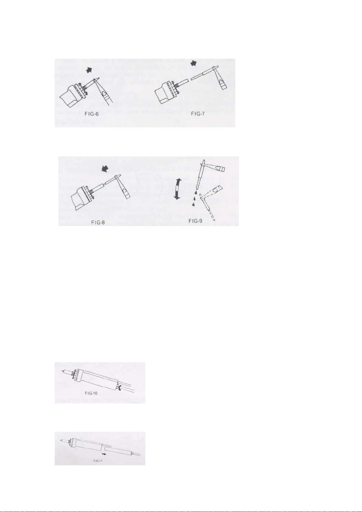
3. Remove solder collector from desolder iron assembly, place finger over the hole
of the collector, depress vacuum switch. There is little suction clean or replace the
collector tube.
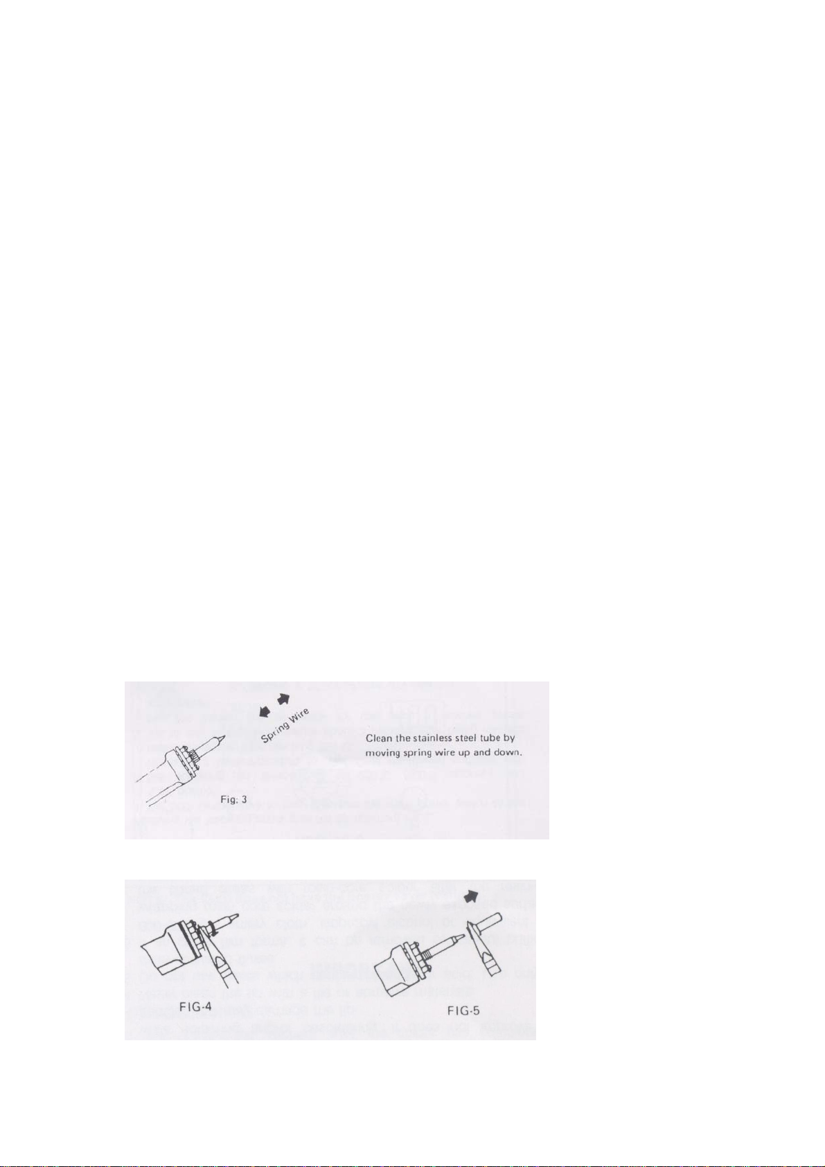
4. Depress vacuum witch, clean the tip tube with spring wire provided if there is no
suction per the “Procedure for Cleaning Clogged Tip” section below.

MAINTENANCE
DESOLDER TIP REPLACEMENT AND DRESSING
Desolder tips can be changed or replaced simply unscrewing the barrel nut assembly.
The station must be turned off and allowed to cool before this operation. If the system
Page.7
is left on without a tip in place, damage to the iron assembly may occur!
After removing the tip, blow out any oxide dust that may have formed in the tip
receptacle. Be careful not to get dust in your eyes. Replace the tip according to
Figures 3-9 and hand tighten the securing screw for the barrel nut assembly. Pliers can
be used to avoid contact with hot surfaces BUT SHOULD BE USED WITH
CAUTION because over tightening may cause damage to the element or fuse the tip
to the element.
PROCEDURE FOR CLEANING CLOGGED TIPS
CAUTION: This procedure is to be working in high temperature. Be careful to avoid
burning your fingers during this operation.
1. Be sure that the spring wire (included) will not go through the nozzle of the
desolder tip.
2. Adjust the heating element to a higher temperature allowing the clogged solder to
melt. Clean the tip by sliding the spring wire up and down until the passage is
clear. (See Fig. 3)
3. Unscrew the barrel nut assembly as in Figures 4 & 5.
8

4. Remove the tip by using a pliers as in Figures 6 & 7.
5. Insert the stainless tube of the tip back in the barrel to melt the solder in around 5
seconds as in Figure 8.
Page.8
6. Remove again and shake out any loose melted solder in the tip per Figure 9, the
tip should now be unclogged. Replace the tip and screw back the retaining barrel
nut assembly but care should be taken not to over tighten!
PROCEDURESFORCLEANINGTHESOLDER
COLLECTOR
CAUTION: The desolder switch must be turned “OFF” and the iron allowed to cool
before this operation.
1. Hold iron as in Figure 10. Press and turn the red knob at the butt of the iron.
2. Slide out the solder collector as in Figure 11. (CAUTION: The solder collector is
glass and thus retains heat, handle with care!)
9

3. Point the collector down while shaking slightly (see Figure 12.) and the waste
solder will fall out. This task must be carried out periodically for proper operation
of the station.
4. Remove cooling strip with a pair of long nose pliers or tweezers.
(see Figures 13 & 14)
5. Clean the cooling strip and glass collector with wire brush (included).
Page.9
PROCEDURE FOR REPLACING FILTERS
SOLDER COLLECTOR FILTERS
1. Be sure the iron/filter assembly have cooled.
2. Hold iron as in Figure 10, press/turn red knob on the butt of iron.
3. Remove solder collector (see Figure 11).
4. Disassemble the solder collector into 2 pars (see Figures 15 & 16).
10

5. Remove old cotton filter and replace (see Figures 17 & 18).
IN LINE FILTERS
1. Unscrew in line filter (see Figure 19) and then pull apart (Figure 20).
INTERCHANGEABLE TIPS FOR LF-8000
11

SMD TWEEZERS OPERATION
Heater operation voltage V.ac 32Vac
Heater power consumption Watt 100W (50Wx2)
ºC 150-430ºC
Temperature range ºF 300-800ºF
Standard tip ﹡46-060102
SMD TIPS FOR TWZ100
TIP TYPES SUITABLE COMPONENTS
*Flat pack IC`s
*Small outlet 8-24 pins
*Flat package tunnel
types
*Dip IC`s
46-060110 (10mm)
46-060115 (15mm)
46-060120 (20mm)
46-060130 (30mm)
*Chip resistors
*Chip capacitors
*SOT
46-060102 (2mm)
46-060103 (3mm)
46-060105 (5mm)
12

13

IMPORTANT: Maintenance note for DIA80 Desoldering Iron
Heater operation voltage V.ac 32Vac
Heater power consumption Watt 80W
ºC 300-450ºC
Temperature range ºF 572-842ºF
Standard tip ﹡44-915412-2075
DIA80 SPARE PARTS LIST
14

15
Change of Cotton Filament (76-1411030):
Please note that the cotton filament cannot be washed with the water. Water drops
would be sucked into the Pump and may cause the pump damaged within 1 to 2
months. If you wash with the water, Cotton filament will turn solid and will
stop the DIA60T working well. Please change at least once 3 to 5 days if you
use 8 hours per day.
Change of Charcoal Filter (78-151500):
Charcoal filter will turn solid if you wash with the water. If you use 8 hours per day
that the Charcoal filter has to be changed within 3 weeks. On the other hand, if
you wash the Charcoal filter and do not dry properly, water drops will be sucked
into the Pump and may cause the pump damaged easily.
Change of Glass Solder Collector (75-160110):
Glass solder collector will be broken easily if the client knocked the DIA60T against
the desktop. The glass collector also needs to be changed every 3 to 5 months
usage.
Maintenance for Desoldering Heater and Tip:
To prevent the desoldering tip being stuck by solder, the desoldering tip has to be
cleaned by a Probe after every time usage. In such ways, desoldering tip’s life
can be lasting longer. Desolder Heater would be probably broken when you
remove the desoldering tip with a pliers careless in hot condition. Slightly
remove the tip with pliers or may use the anti-rusty cleaner when the tip clogged
with the heater and do not forced open. Please read the “Procedure for
Cleaning Clogged Tips” carefully on page.3 & 4 on the manual.
Table of contents
Other Xytronic Soldering Gun manuals

Xytronic
Xytronic IR860 User manual

Xytronic
Xytronic LF-1680 User manual

Xytronic
Xytronic T 1976 User manual

Xytronic
Xytronic LF- 8800 User manual

Xytronic
Xytronic LF-389D User manual

Xytronic
Xytronic LF-988D+ User manual

Xytronic
Xytronic LF-1700 User manual

Xytronic
Xytronic LF-2000 User manual

Xytronic
Xytronic LF-3500 User manual

Xytronic
Xytronic LF-853D User manual