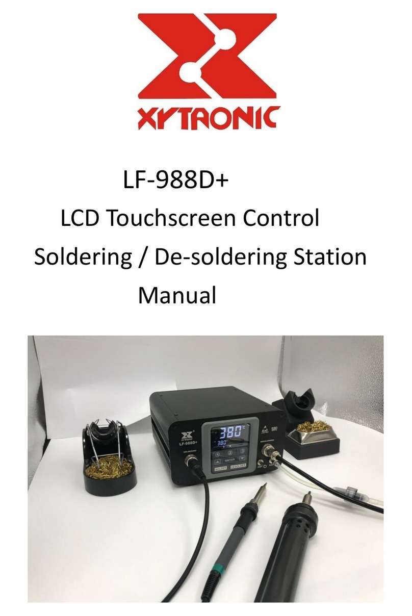
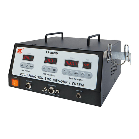
Xytronic LF-1000 User manual

2~(!)
~IC
.
INSTRUCTION ,..'
MANUAL
HI-POWER
SOLDERING STATION
""
71:'
(For Lead Free Application)
I ,/
",-'
! S
I

PRODUCT DESCRIPTION
/'
Thank you for purchasing Xytronic's high power electronic soldering station -the best
solution for your soldering equipment needs! We believe you will be more than
satisfied with many features and the versatility of your new soldering station.
Please carefully read the instruction manual to maximize the advantages of using your
new soldering station.
WARNING: This appliance is not intended for use by children or other persons .
without assistance or supervision if their physical, sensory or mental capabilities
prevent them from using it safely. Children should be supervised to ensure that they
do not play with the appliance.
KEY FEATURES
. ENERGY SAVER: If the station has been idle for more than 15 minutes, it will
automatically kick in. When the "Pause" LED is lit, the energy saver feature has
engaged, decreasing tip temperature by 1/2 which cuts power consumption and
extends tip life (note that lead free solder alloys require a higher soldering
temperature which shortens tip life). Activating the solder wand will disengage the
power saving feature and the unit will immediately ramp up to the preset
temperature.
. DIGITALDISPLAY: This new feature was incorporated into the LF-1000 to provide
timely and accurate temperature readings. Once the desired temperature is
reached, the Set/Read button can be flipped to the" READ" position, insuring a
constant temperature. J
. CELSIUS/FAHRENHEITSWITCH: To address the global market place, a
convenient switch has been incorporated to easily convert from one common
measure to another.
. ISOLATED IRONHOLDERWITH TIP CLEANER: Made of low abrasive brass
shavings instead of conventional sponges to meet RoHS requirement, cleans ;
better and no water is necessary. .
. LOW VOLTAGE OUTPUT WITH SAFETY OPERATION: The power unit is isolated
from the A.C. line by a transformer and allows 32Vac to drive the heating element.
Soldering pencil operates on 32 Volts for safety reasons yet incorporates a 100 W
highpower element for a super-fast heat-up and quick temperature rocovery. The
solderwandisattachedwitha heatresistant,non-burning,flexible7-wirecord. r~-'",
'.
. ESD SAFE AND SPIKE FREE CIRCUITRY: The" Zero Voltage .. electronic
switching design also protects voltage and current sensitive components (CMOS
devices, etc.) against damaging current and transient voltage spikes commonly
produced by less efficient, mechanically switched stations.
-1-
J
'--
I S
'\
I

,
! . EXTERNAL CALIBRATION PORT: for quick, convenient and precise temperature
adjustments.
. DETACHABLE AC POWER CORD WITH PLUG: Engineered AC outlet for
alternating AC power cord with plug and connector specially designed for individual
CE countries requirements.
. OPTIONALSMDTWEEZERSAND/ORFUMEEXTRACTOR:Theadditionalfeature .
is specially designed for SMD chips, SOT, Flat pack ICs' etc. reworking. TWZ100
Tweezers is equipped with 32V/50W' 2 heaters which can be interchangeablewith
solder wand as an option. Be sure before proceeding this operation, the main
switch must be " OFF" to avoid any damage to the unit.
Also the additional use of a tip fume extractor kits can be engineered on the solder
wand in conjunction with production line fume extraction systems. ."
PRODUCTION DESCRIPTION .
TheLFserieshighpowerelectronicallytemperaturecontrolledsolderingstationwere ;;
spcially designed and developed to meet the present and future Lead-free soldering
needs of the electronic production industry. A temperature regulated soldering iron is
essential for marking consistent, reliable soldered connections. It provides all the
benefits of temperature regulation and connects via a highly flexible burn-resistant
lead,and can be easily adjusted in temperature.
The LF series incorporates electronic circuitry which enables the user to alter tip
temperature from 200 to 450'C(392-842'F) without changing tips or heating elements.
Also, with the simple flip of a switch on the front panel, the temperature readout is
changedfrom Celsiusto Fahrenheiteasily. The temperatureismaintained within '""
:t 3 'c (:t 6 'c ) of its operating temperature by a thermocouple sensor placed in the
heating element, allowing the tip to rest against the sensor. The high power results in
both a rapid heat-up and super fast recovery.
The revolutionary "Zero Voltage" electronic switching design also protects voltage
and current sensitive components (CMOS devices, etc.) against damaging current and
transient voltage spikes commonly produced by less efficient, mechanically switched
stations. The power unit is isolated from the A. C. line by a transformer and allows
only 32Vac to drive the heating element.An external calibration port on the face of the
unit for quick and convenient precision temperature adjustments. The many features ,"i~
of the product make it the ideal tool for service and repair technicians as well as
production line soldering operations. This unit is developed to meet the present and
future lead-free soldering needs of the electronic production industry and is ideal for
use at any AC outlet.
-2-
r,(
i S
I

-
WORKING TEMPERATURE
TomeetRoHS requirements,the60/40 lead solder alloys are not allowedin the
productionprocess.Leadfree solderalloys requirea working temperatureof 30'c
(54'F) h~er thanpreviousgenerationelectricalsoldering.Theworkingtemperature
of solderisdetailedbelowandcanvaryfrom manufactureto manufacture.
Meltingpoint 220'c (428'F )
Normaloperation 300-360'c (572-680'F )
Productionlineoperation 360-410'c (680-770'F ) .
Whentheiron'sworkingtemperatureissetwithintheparameterssuitablefor thetype
of solderbeingused,a goodjoint isassured.Toolowof a temperaturewillslow the
rateof solderflowwhilea hightemperaturesetting might burn thefluxinthe solder
andemita heavy,whilesmokeresultingin a dry joint or permanentdamageto the
printedcircuitboard(P.C.B.)andmayalsoshortentiplife.
IMPORTANT:Thetemperatureabove410'c (770'F)isnotrecommendedfornormal ,-
solderingfunctions,butcan beusedfor shortperiodsof timewhenhightemperature
arerequired.
OPERATING INSTRUCTIONS
. Ensure that the working voltage matchesyourpowersupplybeforebeginninguse.
. Check carefully for any damage during transportation.
. This unit contains:
1. Solder wand.
2. Iron holder with brass tip cleaner.
3.AC powercordwith plug.
. Optional parts:
1. Tweezers (can be interchangeable with solder wand.)
2. Fume extraction kit.
OPERATING PROCEDURES
1. Ensure that the base unit power switch is in the "OFF" position.
2. Plug in Solder wand and connect AC power cord to mains" In-let" .
3. Set the temperature control knobs to "MIN" then flip the slide switch under the
digital display to "SET" position and choosing the desire readout temperature by
slide switch to °c or of position and then turn "Mains power switch" to " ON" .
4. Set temperature control knob to 250°C(482'F ). Then tin the surface of the tip by
applying a new covering of solder to protect it.
5. Set temperature control knob to the desired temperature 3 minutes after being
warmed to 250°C(482'F)to extend tip life. ~,
r",
6. Filpthe slide switch to "READ" position once it reached the preset temperature. '
Theunitnowisreadyfor use.
Energy Saver Feature: Please note if the soldering iron idles for more than 15 minutes,
energy saving feature will automatically engage (evident by the" PAUSE" indicator
light ), reducing the idle temperature by 1/2 and extending your tip life.
-3-
j
I S
TI
_o=~--= --

Usingthe soldering pencil will deactivate the energy saver feature and the unit will
immediately ramp up to the preset temperature"
Precision Calibration: There is a calibration port under the digital display on the front
panel.This calibration is to be used in conjunction with an external thermometer"
/"Place the tip on the thermometer and if the actual tip temperature reads higher or
lower than the display on the thermometer then use a 2mm precision screwdriver to
calibrate the temperature. Turning clockwise will lower the temperature (-).Counter .
clockwise will increase the tip temperature (+).
Caution: Soldering irons operate at hightemperatures and can easily burn people or
I objects. Do not touch the tip and heater at any time and keep it a safe distance from
r flammable materials while the unit is on or while its cooling.
Please allow a sufficient time for it to cool before changing tips or servicing the unit!
COMMON CAUSES OF TIP UNWETTING
1. Tip temperature higher than 410°C (770°F).
2. The tip working surfaces are not tinned while the iron idles.
3. Lack of flux in soldering, wicking, repairing, and touch-up operations.
4. Wiping the tip on a high sulfur content, dirty or dry sponges and rags.
5. Touching with organic substances such as plastic, resin, silicone, grease or other
chemicals.
6. Impurities in solder and/or low tin content.
CARE OF TIPS
Caution: The soldering iron can reach very high temperatures. Be sure to turn the unit
off prior to carrying out any maintenance or trouble shooting steps listed below.
IMPORTANT
Remove the tip and clean after moderate to heavy use or at least daily for light usage.
Remove any loose build up in the tip retaining assembly to prevent tip freezing.
The solder tips supplied are iron clad copper and if used properly should maintain
Ioptimum operational life.
1. Always tin the tip before returning it to the holder, turning off the station, or storing
it for long periods of time. Wipe the tip on a brass cleaner (XY459) prior to use.
2. Keeping the iron set at hightemperatures (more than 400°Cor 750°F) will shorten
tip life.
3. Do not use excessive pressure to the tip or rup the joint with the tip while soldering.. ...~,
it does not improve the heat transfer and may damage the tip. (f
4. Apply solder to the joint, not the tip when soldering. The flux is naturally caustic
and thus will eat away the tip.
5. Never clean the tip with a file or abrasive materials.
6. Do not use fluxes which contain chloride or acid. Use only rosin or resin activated
fluxes.
-4- ~~~~~;~!it*~
;~"'f'.'~~~.-
~ . \".i:'""~":i\j:.~~ ,(
,
)
I S
. I
~'c';~"

7. If an oxide film forms on the tip, it can be removed by careful buffing with a
600-800 grit emery cloth, isopropyl alcohol or equivalent and then wrapping rosin
core solder around the newly exposed surfaces. Coat the tinned areas with
rosin-core solder after the resin-core has melted.
NEW TIPS
Applying the following steps will lead to optimum life. .
1. Set temperature to min.then turn the main power switch to the" ON" position.
2. Settemperatureto 250'C(482'F).
3. Coat the tinned surfaces with rosin-core solder after reaching 250'C (482'F).
4. Set to desired temperature after allowing the unit to idle at 250'C for 3 minutes.
5. The iron will be ready for use once it reaches the preset temperature.
IMPORTANT:Remove and clean the tip daily. If a new tip is installed, remove any
loose build up in the barrel assembly, otherwise the tip may fuse to the heating
element or retaining barrel.
SPECIFICATIONSFOR SOLDERWAND
Model LF-1000
Solder wand 210ESD
Heater output 32Vac
Heater ower 100W
Temperature range 200-450 °C (392-842OF)
Standard tip 44-415404
SOLDERINGIRONASSEMBLY 21OESD
ft THEA TER RUBBER 26-'6ii~~~:01 SILICONE
28-012651 42-030303 44-415404 79-210012U COLLAR CABLE
52-070039-01 34-870414
HEATER HOLDER BENDING
ASS'Y GUARD
26A160203-01 26-080190-01
-5-
,
-~
)
i S
I

SMD TWEEZERS OPERATION
~
For Optional TWZ100 SMD Tweezers Operation:
1. Disconnect the soldering iron and change to TWZ100 Tweezers. Be sure the solder
controlling switch is ~OFF' before proceeding this operation to avoid any damage.
2. Throw the solder switch to ~ ON' position once the TWZ100 is connected
properly. Tweezers is ready for use.
. Note:The Tweezerstemperaturewill be lowerabout50°C thanthetypical
solderingirontemperature. .
3. Use only the appropriately designed tips for the job to avoid unnecessary
component damage.
4. Gently pick up and remove components while ensuring that a vertical pick up and
pullout motion is maintained.
5. Use the same procedure when reconnecting the solder wand.
TWZ100-SMD TWEEZERS
Heater type Nichrome
Heater operation voltage V.ac 32Vac
Heater power consumption Watt 100W(50Wx 2)
Tweezer (with tip) TWZ100
°C 150-430°C
Temperaturerange of 300-800°F
Standard tip * 46-060102
SMD TIPS FOR TWZ100
TIP TYPES SUITABLE COMPONENTS ,~ 46-060102 (2mm) * Chip resistors ~ ,.
~ 46-060103 (3mm) * Chip capacitors
[~ 46-060105 (5mm) * SOT i
~ 46-060110(10mm) * FlatpackIC's ~II i
'tfl
~ 46-060115 (15mm) * Small outlet 8-24 pins I, ¥,
~ 46-060120 (20mm) * Flat package tunnel types »r.';~ 46-060130 (30mm) * Dip IC's
U.
"
'9
-6- ..It
~
,.-- ,\
)'
i S
;
.."~"" .,., ;~ -

MAINTENANCE
TIP MAINTENANCEAND DRESSING
Tips can be changed or replaced simply by unscrewing the knurled nut barrel
assembly. The station must be switched off and allowed to cool before this operation
as damage may result if the system is left on without the tip in place!
After removing the tip, blowout any oxide dust that may have formed in the tip
retaining area of the barrel. Be careful to avoid getting this dust in your eyes. Replace
the tip and screw back the knurled nut barrel assembly using only firm hand pressure .
to tighten. Pliers should only be used to tighten the nut to avoid burning your fingers,
but care should be taken not to over-tighten as this could damage the element.
GENERAL CLEANING
The outer cover of the iron and station may be cleaned with a damp cloth using small
amounts of liquiddetergent. Never submerse the unit in liquid or allow any liquidto
enter the case of the station. Never use any solvent to clean the case.
SERVICE
If the iron or station should become faulty or, for some reason not operate normally,
the system should be returned to the service department of your authorized dealer or
service agent or similarly qualified person in order insure proper repairs and to avoid
any hazards from developing.
WARNING: This iron must be returned to its stand when not in use.
WARNING: Keep out of the reach of children.
WARNING: Do not inhale solder fumes.
WARNING: Keep tip and heating element away from the body, clothes and
flammable material when in operation.
INTERCHANGEABLE TIPS
~~~-415401'" *44-415404 em 44-415410 SOmm I+08 1 m J
XV401 -f(I';'" ~=r(I"'.' ~tI3l1'"
44-415402 06mm 44-415405 32mm 44-415411 /,,"'1"' +50
IX~-f ('/32', C~=O=:::D=f (116., ~I:::;- ("""
44-415403 44-415406. 12mm 44-41 5430 5mm+04 J
I XV4Q3 0::=--[ (1"'" I XV"'[~t ""'., 'XV,,", ,,-~J
~~
SMD 81- Top For Soklering
SDIC & PLCC
-7-
~
--l
,,
I \
I
~ --"4-
Table of contents
Other Xytronic Soldering Gun manuals

Xytronic
Xytronic LF-389D User manual

Xytronic
Xytronic LF-3200 User manual

Xytronic
Xytronic LF-988D+ User manual

Xytronic
Xytronic LF-1680 User manual

Xytronic
Xytronic LF-1600 User manual

Xytronic
Xytronic LF-853D User manual

Xytronic
Xytronic IR860 User manual

Xytronic
Xytronic LF- 8800 User manual

Xytronic
Xytronic T 1976 User manual

Xytronic
Xytronic LF-855D User manual