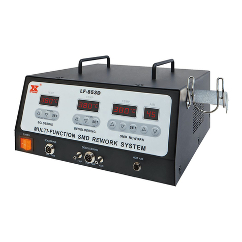
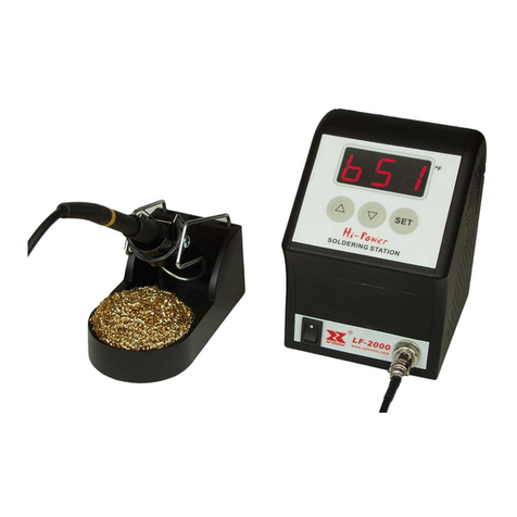
Xytronic LF-855D User manual

OPERATING MANUAL
FOR
LF-855D
Multi-Function
SMD Rework System

1
INTRODUCTION
Thank you for choosing XYTRONIC LF-855D Mul i-Func ion S.M.D. Rework
S a ion. This uni is he bes ool for repairing work, combina ion wi h XYTRONIC
LF-3000 and LF-852D which is specially designed for lead free soldering/desoldering,
surface moun devices wi h empera ure con rolled ho air. The “2 in 1” design ,save
your working space. Please read he opera ing manual carefully o maximize he
advan ages of using your new LF-855D mul i-func ion SMD rework s a ion and keep
his manual readily accessible for fu ure reference.
【
【【
【
WARNING
】
】】
】
and
【
【【
【
CAUTION
】
】】
】
::
【
ELECTRICAL SHCOK
】
Warning and Caution are positioned at critical points in the manual to draw the
user’s attention to significant safety concerns Be sure to comply with the
following warnings and cautions for your safety
This appliance is no in ended for use by children or o her persons wi hou assis ance
or supervision if heir physical, sensory or men al capabili ies preven hem from
using i safely. Children should be supervised o ensure ha hey do no play wi h
appliance. Failure o observe he safe y regula ion will resul in a risk of life and limb.
The manufac urer shall no be liable for damage resul ing from misuse of he uni or
unau horized al era ions.
1. Please unscrew the 4 screws under the bottom enclosure when the unit is
used at the first time (See the procedure on page1 )
2. Ensure he vol age ra ing of he uni and your power supply are iden ical prior o
use.
3. Check carefully of any damage during ranspor a ion.
4. Pu he produc on a safe and s able working able. Table surface should be
consis ed of fire and hea resis an ma erial due o he uni can reach very high
empera ure and po en ially dangerous.
5. During he opera ion, he hea er is ex remely ho , and will cause serious burns if
con ac ed exposed skin. Use gloves and/or any hea resis an ools o pick up he
PCB assembly o elimina e he possibili y of burns.
6. Do no use he produc near combus ible gases or flammable ma erials.
7. Turn he power swi ch OFF and allow he hea er o cool before checking or
replacing hea er and o her par s, or prior o s oring he uni .
8. Keep he appliance clean. This may be used wi h a damp clo h using small

2
amoun of liquid de ergen . Never submerse he uni in liquid or allow any liquid
o en er he s a ion. Never use any solven o clean he case.
9. This uni is designed for soldering/desoldering, ho air SMD rework and should
no be used for any o her purpose wi hou firs consul ing he manufac urer or i s
au horized agen .
10. Keep he uni ou of he reach of children. Young children should be supervised o
ensure ha hey do no play wi h he appliance.
To prevent electrical shock, be sure to take the following precautions:
1. Make sure he uni is grounded. Always connec power o a grounded recep acle.
2. Do no pressure he AC power cord. Be sure he work area is well ven ila ed.
3. Do no bump, hi , pour wa er/liquids or o herwise subjec he hea ing surface o
physical shock. This may damage he hea er.
4. To isola e he equipmen from he mains before commencing repairs or making any
main enance o avoid elec ric shock. This may resul in Dea h or serious injury.
5. Do no expose he uni o mois ure nor use he uni wi h we hands.
6. Turn he power swi ch off and remove he AC power cord by pulling he plug (no
he cable) when he uni will remain unused for a longer period of ime.
7. Do no modify he uni .
Warning
Soldering / Desoldering Function Warning
◆ Always place he soldering & desoldering irons in i s original holder when no
being used.
◆ Keep he soldering and desoldering ip and hea ing elemen away from he body,
clo hes and flammable ma erial when in opera ion.
◆ The soldering and desoldering ip and he hea ing elemen are s ill remaining ho
af er being swi ched off. Ensure ha you do no ouch he ips and he hea ing
elemen s.
◆ For your heal h, do no inhale solder fumes.
◆ You mus no under ake work on live par s. Only he echnician is permi ed o
under ake repairs. Use he original replacemen par only.
Hot Air Function Warning
● To last the life of the heating element, not recommend continuously using at
low air flow and high temperature Le he hea ing elemen be cooler af er using
a maximum 20 minu es. Ensure ha i is placed back on i s cooling s and o cool
down be ween rework opera ions. Also, do no swi ch he hand ool on while i is
in he cooling s and. Fail to comply with the instructions may result in damage
to the hand tool
● Do not aim the hot air at your eyes Do no allow he ho air from he hand ool
o aim he eyes as serious eye damage may occur.

3
● The hot air pencil can produce a lot of heat Do no allow he hea er and he
nozzle o con ac exposed skin as burning may occur. To elimina e he possibili y
of burns, allow ime for he equipmen o cool before commencing main enance.
● Death or serious injury may result from electric shock I is herefore essen ial
o isola e he equipmen from he mains before commencing repairs.
● Keep the hot air away from the body, clothes and flammable material when
in operation The nozzle me al is in a high empera ure s a us, do no ouch he
nozzle! Always replace he hand ool o i s original holder when no being use.
The nozzle and he hea ing elemen are s ill remaining ho af er being swi ched off.
Ensure ha you do no ouch hem.
● Do not block the air outlet in full area of the nozzle, or it may cause the heat
reflection and damage the heating element
● Do not leave when the machine is on operating: S are a he nozzle when he
rework s a ion is on opera ing, so as no o burn your body or o her objec s. Turn
off he machine and unplug he power cord when you are leaving and pu he ho
air handle o he holder in one side of he machine. The nozzle is s ill remaining
ho af er being swi ch off on some ime. Ensure ha you do no ouch he nozzle.
● Do not use if damaged: If he pump doesn’ work or he rework s a ion becomes
faul y, discon inue using immedia ely. To comply wi h safe y s andards, he pump
or o her par mus only be replaced by au horized echnicians as special purpose
ools are required. Only he echnician is permi ed under ake repairs. Use he
original replacemen par only.
● Remember unplug in the power cord: The s a ion mus be swi ched off and he
power cord mus be unplug-in before replacing he fuse in AC socke in rear side
of he machine.
● Do no unplug he power cord; when he power swi ch is urned off, he cooling
sys em will begin o work au oma ically, he empera ure falls down o 100℃(212
℉) o pro ec he hea er, remember ha do no unplug he power cord a his ime
un il he uni s op working.
PRODUCT FEATURES
◆ “2 in 1” by design, saving working space, owning hree func ion, can grea ly mee
he users need.
◆ Wi h special in elligen chip microcompu er con rol design, double LED display
opera ing by pressing keys, make i convenien and comfor able opera ion.
◆ Selec ion free for Fahrenhei and Cen igrade (Celsius) empera ure.
◆ “Password selec ion”: Tempera ure or air blow by digi al display readou , easy o
read. The empera ure can be locked by “password” code ha is convenien for
produc ion line managemen .

4
Soldering / Desoldering Function
◆ HEATER/SENSOR FAILED DETECTION: If sensor circui failed ha he
display reads “S--E” and cu off he hea er power. If hea er circui failed he
display will read “H--E” and cu off he hea er power.
◆ TEMPERATUE “LOCK-OUT” FEATURE: The empera ure can be locked by
“password” code ha is convenien for produc ion line managemen .
◆ ESD SAFE AND SPIKE FREE CIRCUITRY: The “Zero Vol age” elec ronic
swi ching design also pro ec s vol age and curren sensi ive componen s (CMOS
devices, e c.) agains damaging curren and ransien vol age spikes commonly
produced by less efficien , mechanically swi ched s a ions.
◆ LIGHTWEIGHT SOLDERING IRON: Ergonomic mini handle ha s ays cool
and preven s opera or fa igue.
◆ ENERGY SAVER MODE: If he s a ion has been idle for 20 minu es, he energy
saver fea ure will au oma ically engage, he empera ure goes down o 150℃
from he se empera ure for Soldering and 200℃ from he se empera ure for
de-soldering Ac iva ing he solder/desolder wands will disengage he power
saving fea ure and he uni will immedia ely ramp up o he prese empera ure.
When over 40 minu es wi hou opera ion he main power will be swi ched off o
“sleep mode” which cu s power consump ion and ex ends ip life.
Please note: You have o urn off he power swi ch firs and hen swi ch “ON”
again o commence work when he uni goes o “Sleep” mode.
◆ IRON WORKING OPTION: When he users don’ use he soldering or
desoldering func ion ,or hey also se by pressing keys “ SET + ▲”,a his ime,
he iron which you se will en er he power off suspend s a us. I means ha he
hea er power is cu off. If press “▼”then he hea er power will be on.
Hot Air Funciton
◆ Wi h he high power hea ing elemen , hea up quickly, he momen ary power can
reach 600W.
◆ Tempera ure adjus able, sui s for removing QFP, SOP, PLCC or SOJ chips e c.,
especially he buil in s a ic free circui design is safe y for he sensi ive elemen s
like CMOS ICs.
◆ SENSOR /PUMP FAILED DETECTION: If sensor circui failed ha he display
read “S--E” and cu off he hea er power. If he pump circui failed ha he display
read ”P-E” and cu off he hea er power.
Au o-cooling design: When he power swi ch off, he cooling sys em will begin o
work au oma ically, he empera ure falls down o 100℃(212℉) o pro ec he
hea ing elemen from burning ..
◆ Hea ing elemen au o-pro ec ing func ion: When hea ing elemen reaching a high
empera ure which can be pro ec ed au oma ically, o las ing he life of hea ing
elemen .

5
SPECIFICATIONS
Model LF-855D Mul i-func ion SMD REWORK STATION
Power Vol age 220-240Vac 50Hz 100-120Vac 60Hz
Fuse(Fas Type) 5A(fas ype) 10 A(fas ype)
Power Consump ion (Max)
700W
Weigh 7.5kg
Solder
Power Consump ion 90W
Tempera ure Range 100℃-520℃(212℉-896℉)
Sleeping Tempera ure 100℃(212℉)
Tempera ure correc ion range
+99℃~-99℃/+178℉~-178℉
Defaul se ing
100℃
F-1: “000”
F-2:“00”
F-3:“100”
F-4:“℃”
Ho
Air
Power Consump ion 600W
Air Flow 1.5 L / Min -40L / Min
Tempera ure range
100℃-480℃/212℉-896℉
Air Flow 00-99
Defaul se ing
F-1:“000”
F-2“℃”
Tempera ure 100℃ Air Flow 00

6
BRIEF INTRODUCTION OF PANEL FUNCTIONS:
Front panel
○
1 Main power switch
○
2SIA socket
○
3HOT-AIR Hole
Soldering Function Part
○
4“▲”: Temperature increasing (UP)
○
5 “▼”: Temperature decreasing (Down)
○
6 Temp Display
○
7 Heat indicating light
○
8 “SET”: Function key
Hot Air Function Part
○
9 “▲”: Temperature increasing (UP)
○
10 “▼”: Temperature decreasing(Down)
○
11 Temp Display
○
12 Heat indicating light
○
14 “▲”: Hot air blow (UP)
○
15 Temp Display
○
16 “▼”: Hot air blow (DOWN)

7
FUNCTION INTRODUCTION
Soldering /desoldering function introduction
(Bo h soldering and desoldering func ion can be se in he same way.)
TEMPERATURE SETTING: (No password se )
1. Increase empera ure: By pressing “▲” key one ime, he digi al will be increase
“1” numeral. If pressing “▲” key over 2 seconds hen he digi al numerals will be
forwarded coun ing con inuously ill he empera ure up o wha you desire o se .
2. Decrease empera ure: By pressing“▼” key, he same procedure as above.
PARAMETER SETTING:
1. Press “SET” key and hold for a leas 5 seconds un il display shows“— — —”
sign hen release he “SET” key. The sign “— — —” s ar s o flash and reminding
he user o inpu he mode lock password “010” (fixed). If he user inpu s he same
number as “010”, he uni will en er he modes selec ion procedure, o herwise, he
uni will be back from he curren mode au oma ically.
2. Af er he uni en ers he Modes selec ion, he LED will display “F-0”and flash.
Press “▲”or “▼” key o selec modes. If he user doesn’ press “▲” or “▼” key
wi hin 15 seconds or press “SET” key one ime, hen he uni will be immedia ely
back from he Parame er Se s a us.
For example: F-0 → F-1 → F-2 → F-3 →F-4
↑ ↓
← ← ← ← ←
3. Password Se ing:
When he LED displays “F-1” and flashes, press “SET” key one ime and he
uni en ers he Password Se s a us. A his momen , he LED displays he pre-se
value. Press “▲” or “▼” key o change password se value. If he user se s
“000” ha means he uni will be under he s a us of no password. If he user se s
“100” hen means he uni will be under he password s a us. Press “SET” key
once o finish password se ing and he uni will backup mode, he user can
con inue se o her modes or back from he se ing mode.
4. Tempera ure Correc ion Se ing:
Press “SET” key once when he LED displays “F-2” and flashes ha he uni
en ers he Tempera ure Correc ion Mode. A his momen , he LED displays
prese correc ion value.
A: Opera ion of Cen igrade empera ure correc ion(+99℃~-99℃):
Press “▲” or “▼” key o change he empera ure correc ion value. The firs digi
“— ” means minus (ac ual empera ure is down), “No display” means plus
(ac ual empera ure is up).
B: Opera ion of Fahrenhei empera ure correc ion value(+178℉~-178℉):
Press “▲” or “▼” key o change he empera ure correc ion value. The firs digi
“— ” means minus (ac ual empera ure is down), “No display” means plus. Press

8
“SET” key once o finish he empera ure correc ion and he uni au oma ically
backup mode. The user may con inue se o her modes or back from he curren
se ing mode.
Example for empera ure correc ion: The curren se empera ure value is 300℃,
however, he ac ual empera ure is only 290℃. So i needs o correc by +10℃.
Correc ion me hod: if he curren correc ion value is 00 or -00; hen change i o
10. If he curren correc ion value is -20, hen change i o -10. If he curren
correc ion value is 20, hen change i o 30.
5. Sleep Mode Se :
Press “SET” key one ime when he LED displays “F-3” and flashes, he uni
en ers he Sleep mode s a us. A his momen , he LED displays he pre-se value.
Press “▲” or “▼” key o change he se value. If se value reads “000” ha
means he uni se in “Sleep” mode releasing s a us. If he display read “100” ha
means he uni se in “Sleep” mode. Press “SET” key once o finish he sleep
mode se ing, hen he uni au oma ically backup. The user may con inue se
o her modes or back from curren se mode.
Please note the manufacturer original design will keep in “Free” status
without setting “Sleep” mode
6. Wake-up me hod:
① Tempera ure Down Suspend: If he uni is se a Sleep mode func ion, af er 20min
idleness, he sys em will en er he sleep mode au oma ically, he empera ure of
soldering will go down o 150℃ (302
℉)
/ and he LED displays a “ 150” and
flashes, he empera ure of desoldering will go down o 200℃ (392
℉)
and he
LED displays a “ 200” and flashes
.
Ac iva ing he solder wand will disengage he
suspend s a us and he uni will immedia ely ramp up o he prese empera ure.
There are hree me hods o wake-up he Tempera ure Down Suspend.
a. Soldering: Pick up he solder wand HF-90 and shake i gen ly.
b. Press any key of he uni .
c. Turn off he main swi ch and res ar .
○
2
Power off Suspend: If he uni en ers he Sleep mode over 40min wi hou wake-up,
he uni will en er au oma ically he power off suspend s a us. I means he hea er
power will be cu off and he LED displays “— — —” and flashes. You can wake
i up by pressing “▼” key when you reuse he iron or urn off he main swi ch and
re-swi ch on.
7. Fahrenhei and Cen igrade (Celsius) empera ure selec ion
When empera ure display window shows "F-4" and blinking, press he "SET"
bu on, a his ime , he sys em en ers he degrees Fahrenhei and Cen igrade
empera ure selec ion func ion, indica ing he empera ure of he window shows
he curren s a us. Press "▲" or "▼" key o change he empera ure selec ion
s a us. I expressed as degrees Celsius empera ure value if se o “℃”; i shows
as degrees Fahrenhei empera ure if se o ℉

9
WORKING TEMPERATURE
SOLDERING
To mee RoHS requiremen s, he common 60/40 lead solder alloys are no allowed in
he produc ion process. Lead free solder alloys require a working empera ure of 30℃
(54℉) higher han previous genera ion elec rical soldering. The working empera ure
of solder is de ailed below and can vary from manufac ure o manufac ure.
Mel ing poin 220℃ (428℉)
Normal opera ion 300-360℃ (572-680℉)
Produc ion line opera ion 360-410℃ (680-770℉)
When he soldering iron’s working empera ure is se wi hin he parame ers sui able
for he ype of soldering being used, a good join assured. Too low of a empera ure
will slow he ra e of solder flow while a high empera ure se ing migh burn he flux
in he solder and emi a heavy, whi e smoke resul ing in a dry join or permanen
damage o he prin ed circui board (P.C.B) and may also shor en ip life.
IMPORTANT: The empera ure above 410℃ (770℉) is no recommended for
normal soldering func ions, bu can be used for shor periods of ime when high
empera ures are required.
Hot air function introduction
TEMPERATURE SETTING: (No password se )
1. Increase empera ure: By pressing “▲” key one ime, he digi al will be increase
“1” numeral. If pressing “▲” key over 2 seconds hen he digi al numerals will be
forwarded coun ing con inuously ill he empera ure up o wha you desire o se .
2. Decrease empera ure: By pressing“▼” key, he same procedure as above.
AIR FLOW SETTING: (No password se )
1 Increase empera ure: By pressing “▲” key one ime, he digi al will be increase
“5” numeral. If pressing “▲” key over 2 seconds hen he digi al numerals will be
forwarded coun ing con inuously ill he empera ure up o wha you desire o se .
2. Decrease empera ure: By pressing“▼” key, he same procedure as above.
PARAMETER SETTING:
1. Press “SET” key and hold for a leas 3 seconds un il display shows“— — —”
sign hen release he “SET” key. The sign “— — —” s ar s o flash and reminding
he user o inpu he mode lock password “010” (fixed). If he user inpu s he same
number as “010”, he uni will en er he modes selec ion procedure, o herwise, he
uni will be back from he curren mode au oma ically.
2. Af er he uni en ers he Modes selec ion, he LED will display “F-0”and flash.
Press “▲”or “▼” key o selec modes. If he user doesn’ press “▲” or “▼” key
wi hin 15 seconds or press “SET” key one ime, hen he uni will be immedia ely
back from he Parame er Se s a us.

10
For example: F-0 → F-1 → F-2
↑ ↓
← ← ←
3. Password Se ing:
When he LED displays “F-1” and flashes, press “SET” key one ime and he uni
en ers he Password Se s a us. A his momen , he LED displays he pre-se value.
Press “▲” or “▼” key o change password se value. If he user se s “000” ha
means he uni will be under he s a us of no password. If he user se s “100” hen
means he uni will be under he password s a us. Press “SET” key once o finish
password se ing and he uni will backup mode, he user can con inue se o her
modes or back from he se ing mode.
4. Fahrenhei and Cen igrade (Celsius) empera ure selec ion
When empera ure display window shows "F-4" and blinking, press he "SET"
bu on, a his ime, he sys em en ers he degrees Fahrenhei and Cen igrade
empera ure selec ion func ion, indica ing he empera ure of he window shows he
curren s a us. Press "▲" or "▼" key o change he empera ure selec ion s a us. I
expressed as degrees Celsius empera ure value if se o ℃; i shows as degrees
Fahrenhei empera ure if se o ℉.
OPERATING INSTRUCTIONS
NOTE: In order to protect the pump during transportation, he pump in he
machine is igh ened by he 4 screws under he bo om enclosure. Please unscrew he
4 screws when he machine is used a he firs ime. (See Fig. A).
Fig. A

11
1. Ensure ha he working vol age ma ches your power supply before beginning use.
2. Check carefully for any damage during ranspor a ion.
3. This uni con ains:
A: HF-90 Soldering iron assembly wi h ip..
B: AC Power cord wi h plug.
C:Ho air gun
E:Accessories included:
a. cleaning brushes
b. 4pcs nozzles
c. iron holders
d. Ho air gun holder
OPERATING PROCEDURES
Caution: Check carefully for any damage during ranspor a ion and ensure ha he
working vol age ma ches your power supply before plugging in he s a ion.
1. Ensure ha he base uni ’s power swi ch is in he ‘OFF” posi ion.
2. Plug in “Solder” wands. Pu he ho air gun o he (holder)
3. Connec AC power cord o mains “In-Le ”.
4. Turn swi ch “ POWER SWITCH” o “ON” posi ion and he swi ch led will be
ligh .
5. All of he func ions ( Soldering and Ho air gun )will work a he same ime af er
urning he power swi ch , and hen he corresponding empera ure LED or wind
LED display will be ON and show he value.
6. Users can urn off he he Soldering func ion by pressing he
key”SET+UP” , hen he corresponding LED display will show “_ _ _”.
NOTE: I means ha he corresponding hea er power is cu off.A his ime , he
users can only use he ho air func ion.
Pressing on he “▲”on can reuse the corresponding function.
A: Soldering function / Desoldering function option
1) Press he “▲” key up un il he empera ure o 250℃ (482℉) (If se o degrees
Cen igrade, he empera ure display window of he upper righ corner shows ℃, if
se o degrees Fahrenhei , he empera ure display window of he upper righ corner
shows ℉).
2) Then in he surface of soldering ips by applying a new covering of solder o
pro ec i .
3) You can se he desired empera ure se ing by pushing he “up” or “down” key.
When he empera ure reaches o he desired empera ure ha he hea ing indica or

12
ligh will be flashed on and off o main ain he se empera ure. The uni now is
ready for use.
CAUTION: Do no ouch any of he irons a any ime while he uni is on or while
i ’s cooling as hey will s ill be ho .
COMMON CAUSES FOR TIP UNWETTING
1. Tip empera ures higher han 410℃ (770℉).
2. The ip working surfaces are no inned while he iron idling.
3. Lack of flux in soldering, wicking, repair, and ouch-up opera ions.
4. Wiping he ip on a high sulfur con en , dir y or dry sponge.
5. Con ac wi h organic subs ances such as plas ic, resin, silicone, grease and o her
chemicals.
6. Impuri ies in he solder and/or low in con en .
CARE OF TIPS
CAUTION: The soldering irons can reach very high empera ure. Be sure o urn he
uni off prior o carrying ou any main enance or rouble shoo ing s eps lis ed below!
IMPORATNT:
Remove he ip and clean af er each modera e o heavy use or daily for ligh usage.
Remove any loose build up in he ip re aining assembly o preven ip freezing.
Solder ips supplied are iron clad copper and if used properly should main ain
op imum life.
1. Always in he ip before re urning i o he holder, urning off he s a ion, or
s oring i for long periods of ime. Wipe he ip on a brass cleaner prior o use.
2. Keeping he iron se a high empera ures (more han 400℃ or 752℉) will
shor en ip life.
3. Do no use excessive pressure on he ip or rub he join wi h he ip while
soldering and i does no improve he hea ransfer and may damage he ip.
4. Apply solder o he join , no he ip when soldering. The flux is na urally caus ic
and hus will ea away he ip.
5. Never clean he ip wi h a file or abrasive ma erials.
6. Do no use fluxes which con ain chloride or acid. Use only rosin or resin ac iva ed
fluxes.
7. If an oxide film forms, i can be removed by careful buffing wi h 600-800 gri
emery clo h, isopropyl alcohol or equivalen and hen he inned areas wi h
rosin-core solder af er he resin-core has mel ed.

13
NEW TIPS
Applying he following s eps give he ip op imum life.
1. Se bo h empera ures o min. hen urn he main power swi ch o he “ON”
posi ion.
2. Se soldering ip empera ure o 250℃ (500℉ approx.) and desoldering ip
empera ure o min. Coa he inned surfaces wi h rosin-core solder af er reaching
250℃.
3. Se o he desired empera ure abou 3 minu es af er being warmed ha he s a ion
will be ready for sue once i reaches prese empera ure.
IMPORTANT:
Remove and clean he ip daily. If a new ip is ins alled, remove any loose build up
in he barrel assembly, o herwise he ip may fuse o he hea ing elemen or
re aining barrel.
1. collec or ube.
2. Depress vacuum wi ch, clean he ip ube wi h spring wire provided if here is no
suc ion per he “Procedure for Cleaning Clogged Tip” sec ion below.
B: Hot air function option
OPERATING PRECAUTIONS
1. Make sure bo h hea er and nozzle are cool before a aching he nozzle.
2
.
Cau ion High Tempera ure Opera ion
Bo h nozzle and ho air are ex remely ho and can cause burns. Never ouch he
nozzle and hea er assembly or allow he ho air o blow agains your skin. Ini ially,
he iron may emi whi e smoke, bu his will soon dissipa e.
Operation Setup
1. Selec he Nozzle ha ma ches he size of he IC. A ach he nozzle when bo h
hea ing elemen and he nozzle are cool and he uni is urned off and unplugged.
2. Loosen he screw on he nozzle and a ach nozzle.
3. Press “▲” or“▼”key on he ho air func ion panel o choose he desired
empera ure or air flow.
4. Press “▲”or “▼” key o choose he desired air flow on he righ side of he fron
panel. The speed will change 5 degrees by pressing he keys “▲” or“▼” a a ime.
5. Af er adjus ing he air flow and empera ure and wai for he empera ure o
s abilize for a shor period of ime.
IMPORTANT: Do no force he nozzle or pull on he edge of he nozzle wi h pliers.
Also, do no igh en he se -screw oo igh ly.

14
Suitable for desoldering of SMD components such as SOIC, CHIP, QFP, PLCC,
BGA etc
QFP De-soldering
1. Melt the solder: Hold he iron so ha he nozzle is loca ed direc ly over, bu no
ouching he IC and allow he ho air o mel he solder. Be careful no o ouch he
leads of he IC wi h he nozzle.
2. Remove the IC: Once he solder has mel ed, remove he IC by lif ing he pliers.
3. Turn the power switch off: Af er he power swi ch is off, an au oma ic blowing
func ion begins sending cool air hrough he pipe in order o cool bo h he hea ing
elemen and he handle. So do no disconnec he plug during his cooling process.
4. In case you don’ use he uni for a long ime, disconnec he plug.
Note: Af er he power swi ch off abou one minu e la er, he empera ure will fall
down o 75℃ (167℉) and power au oma ically shu off.
5. Remove any remaining solder: Af er removing he IC, cleaning he remaining
solder chips wi h a wick or desoldering ool.
Note: For SOP, PLCC e c. would recommend by using weezers iron o desolder.
QFP Soldering
1. Apply the solder paste: Apply he proper quan i y of solder pas e and flux
(preferably no-clean) and place ins all he SMD on he PCB.
2 Preheat SMD
3. Soldering: Hea he lead frame evenly.
4. Washing: When soldering is comple ed, wash he area wi h a defluxer.
Note: While here are many advan ages of ho air SMD rework, i is also possible
o have defec s for soldering BGA. Will recommend o inspec all soldering join s
closely.
PROCEDURE FOR REPLACING HOT AIR GUN HEATING
ELEMENT
1.Unscrew he 3 screws on handle hen ake ou he handle cover.(See Fig.1 below)
2.
Disconnec he grounding wire jack and pull he hea ing elemen ou from he
s ainless s eel ube.
Important: Do no damage or loss he quar z glass and /or insula ion
mica inside of he s ainless s eel ube.
Caution
:The main swich must be “off” and allow the iron to cool
before attemptling the following procedure

15
(See Fig.2 below )
1. Pull he defaul hea er off and replace a new one hen re-assembly he hea er
according he backward procedure.
(See Fig.3)
SPARE PART
Part No 79-460012 Heating element 120Vac,60Hz,600W
Part No 79-560012 Heating element 230-240Vac,50Hz,600W
INTERCHANGEABLE ACCESSORY
1.INTERCHANGEABLE TIPS
Soldering tips for SIA : HF-90
I B 1C
2C
3C k
1.6D 4C 4.2D

16
2.INTERCHANGEABLE NOZZLES
Table of contents
Other Xytronic Soldering Gun manuals

Xytronic
Xytronic LF-1600 User manual

Xytronic
Xytronic LF-2000 User manual

Xytronic
Xytronic LF-3500 User manual

Xytronic
Xytronic LF-3200 User manual

Xytronic
Xytronic LF-389D User manual

Xytronic
Xytronic LF- 8800 User manual

Xytronic
Xytronic IR860 User manual

Xytronic
Xytronic LF-988D+ User manual

Xytronic
Xytronic LF-853D User manual

Xytronic
Xytronic LF-1700 User manual