Yaesu FTDX101MP User manual

YAESU MUSEN CO., LTD.
CAT Operation Reference Manual
101MP
101D

1
CAT (Computer Aided Transceiver)Operation
Overview
The CAT (Computer Aided Transceiver) System in the FTDX101MP/FTDX101D transceiver provides control of
frequency, VFO, memory, and other settings such as dual-channel memories and diversity reception using an
external personal computer. This allows multiple control operations to be fully automated with single mouse clicks,
or keystroke operations on the computer keyboard.
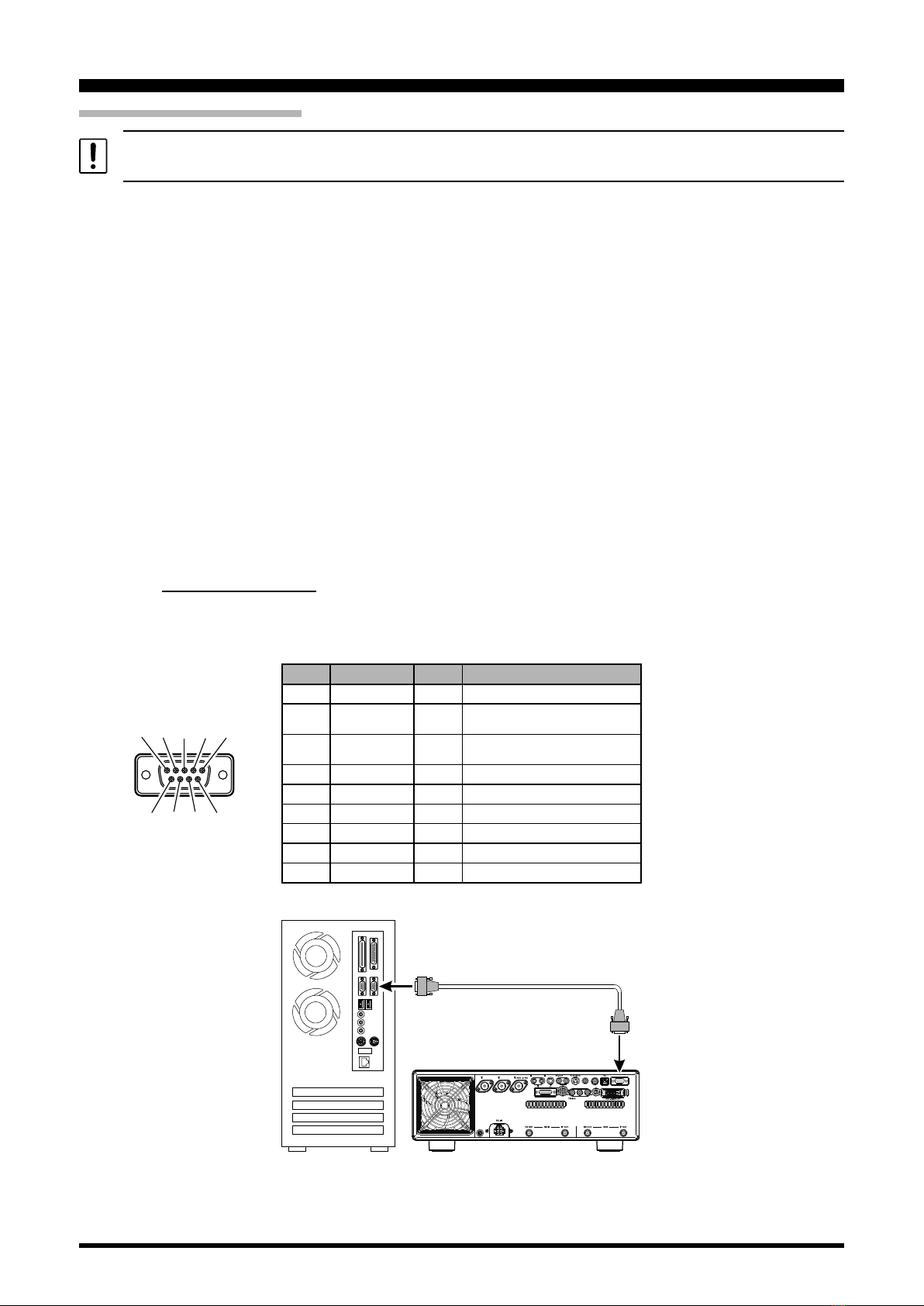
Using the USB Cable
The FTDX101MP/FTDX101D transceiver has a built-in USB to Dual UART Bridge, allowing direct connection
from the rear-panel USB jack to the USB jack of a computer without the need for an interface device, simply use
a USB cable to connect to the USB jack on the computer.
To connect to a PC using a USB cable, a Virtual COM port driver must be installed on the PC.
Visit the Yaesu website http://www.yaesu.com/ to download the Virtual COM port driver and Installation Manual.
YAESU MUSEN does not produce CAT System operating software due to the wide variety of personal computers
and operating systems in use today. However, the information provided in this chapter explains the serial data
structure and opcodes used by the CAT system. This information, along with the short programming examples,
is intended to help you start writing programs on your own. As you become more familiar with CAT operation,
you can customize programs for your operating needs and utilize the full operating potential of this system.
ANT 1 ANT 2
EXT SPKR KEY
ACC TUNER
PTT
METER
GND
LINEAR +13.8V
REM EXT ALC RS-232C
A B
USB
USB
USB Cable
Personal Computer
FTDX101D
How to Conrm the Installation, and the COM Port Number
AftertheFTDX101MP/FTDX101Dandcomputerareconnected,conrmthatthevirtualCOMdriverhasbeen
installed successfully:
1. Press and hold the ON/OFF switch to turn the transceiver ON.
2. Connect the transceiver and PC with a commercially available USB cable (A-B).
3. Open the “Device Manager” screen in Windows.
4. On the Device Manager screen, double-click “Port (COM & LPT)”.
“Silicon Labs Dual CP210x USB to UART Bridge : Enhanced COM Port (COM**)”
“Silicon Labs Dual CP210x USB to UART Bridge : Standard COM Port (COM**)”
*(The number in the “(COM**)” portion may vary from computer to computer.)
The FTDX101MP/FTDX101D contains two virtual COM ports, an Enhanced COM Port and a Standard COM Port.
Theseportsoerthefollowingfunctions:
・Enhanced COM Port: CAT Communications (Frequency and Communication Mode Settings)
・Standard COM Port: TX Controls (PTT control, CW Keying, Digital Mode Operation)
TheaboveexampleindicatesthatCOM5canbeusedforCATcommunicationsandrmwareupdating,while
COM6 can be used for TX control (PTT, CW Keying, Digital Mode Operation).

2
CAT (Computer Aided Transceiver)Operation
Whenperformingsoftwareportconguration,selecttheCOMportnumbersthatwereconrmedusingthe
procedureabove,usethetwoconrmedCOMportnumbersforeachsoftwarefunction.Thefrequencyand
communication mode and PTT control can be set from the software, and CW keying, digital communication,
etc. can be performed simultaneously.
Whenperformingsoftwareportconguration,selecttheCOMportnumbersthatwereconrmedusingthe
procedure above.
・If a “!” or “X” is displayed for the port on the Device Manager, uninstall and reinstall the virtual COM driver.
・Ifatransceiverwithadierentserialnumberisconnectedandturnedon,dierentCOMportnumbers
willbeassignedtoit,makingitpossibletoperformindividualCOMportcongurationsforseparate
transceivers.
・When using the USB cable for TX control, the transceiver may switch to the transmit mode when the
computer is started.
・Always close the application on the computer before disconnecting the USB cable.

3
CAT (Computer Aided Transceiver)Operation
Using the RS-232C Cable
When using an RS-232C cable, the “PS” command (POWER SWITCH) is not available. Therefore, the transceiver
cannot be turned ON with the CAT command.
The FTDX101MP/FTDX101D transceiver has a built-in level converter, allowing direct connection from the rear-
panel RS-232C jack to the serial port of your computer without the need of any external boxes.
The RS-232C jack cannot be used when the external antenna tuner is selected on the menu mode “OPERATION
SETTING”→“GENERAL”→“TUNER SELECT”.
• TUNER SELECT
Function: Internal and external antenna tuner settings.
Available Values: INT / EXT1 / EXT2 / EXT3
Default Setting: INT
Description: Select whether to use the “built-in antenna tuner” or the “external antenna tuner”. When using
an external antenna tuner, select the antenna connector to be connected.
INT: Use the built-in antenna tuner. External antenna tuner cannot be used.
EXT1: Use an external antenna tuner connected to the ANT 1 connector.
EXT2: Use an external antenna tuner connected to the ANT 2 connector.
EXT3: Use an external antenna tuner connected to the ANT 3/RX connector.
NOTE: The RS-232C jack cannot be used while using the external antenna tuner.
The built-in antenna tuner cannot be used with an antenna connector connected to an external an-
tenna tuner.
You will need a serial cable for connection to the RS-232C (serial or COM port) connector on your computer.
Purchase a standard serial cable (not the so-called “null modem” type), ensuring it has the correct gender and
numberofpins(someserialCOMportconnectorsusea9-pinratherthan25-pinconguration).Ifyourcomputer
uses a custom connector, you may have to construct the cable. In this case, refer to the technical documentation
supplied with your computer for correct data connection.
Pin No. Pin Name I/O Function
N/A --- ---
SERIAL OUT Output Outputs the Serial Data from the
transceiver to the computer.
SERIAL IN Input Inputs the Serial Data from the
computer to the transceiver.
N/A --- ---
GND --- Signal Ground
N/A --- ---
RTS --- ---
CTS --- ---
N/A --- ---
ANT 1 ANT 2
EXT SPKR KEY
ACC TUNER
PTT
METER
GND
LINEAR +13.8V
REM EXT ALC RS-232C
A B
RS-232C
COM
Personal Computer
RS-232C “Straight” Cable
FTDX101D
① ② ③ ④ ⑤
⑧ ⑨⑦⑥

4
CAT (Computer Aided Transceiver)Operation
Control Command
A computer control command is composed of an alphabetical command, various parameters, and the terminator
that signals the end of the control command.
Example: Set the MAIN Band frequency to 14.250000 MHz.
FA 014250000 ;
Command Parameter Terminator
There are three commands for the FTDX101MP/FTDX101D as shown below:
Set command: Set a particular condition (to the FTDX101MP/FTDX101D)
Read command: Reads an answer (from the FTDX101MP/FTDX101D)
Answer command: Transmits a condition (from the FTDX101MP/FTDX101D)
For example, note the following case of the FA command (Set the MAIN Band frequency):
To set the MAIN Band frequency to 14.250000 MHz, the following command is sent from the computer to the
transceiver:
“FA014250000;” (Set command)
To read the MAIN Band frequency, the following command is sent from the computer to the transceiver:
“FA;” (Read command)
When the Read command above has been sent, the following command is returned to the computer:
“FA014250000;” (Answer command)
Alphabetical Commands
A command consists of 2 alphabetical characters.
You may use either lower or upper case characters. The commands available for this transceiver are listed in the
“PC Control Command Tables” on the following pages.
Parameters
Parameters are used to specify information necessary to implement the desired command.
The parameters to be used for each command are predetermined. The number of digits assigned to each param-
eterisalsopredetermined.Refertothe“ControlCommandList”andthe“ControlCommandTables”tocongure
the appropriate parameters.
Whenconguringparameters,becarefulnottomakethefollowingmistakes.
For example,
when the correct parameter is “IS00+1000” (IF SHIFT):
IS001000;
Notenoughparametersspecied(Nodirection(+)givenfortheIFshift)
IS00+100;
Not enough digits (Only three frequency digits given)
IS00_+_1000;
Unnecessary characters between parameters
IS00+10000;
Too many digits (Five frequency digits given)
Note: If a particular parameter is not applicable to the FTDX101MP/FTDX101D, the parameter digits should be
lledusinganycharacterexcepttheASCIIcontrolcodes(00to1Fh)andtheterminator(;).
Terminator
To signal the end of a command, it is necessary to use a semicolon (;). The digit where this special character must
appeardiersdependingonthecommandused.

5
CAT (Computer Aided Transceiver)Operation
Command Function Set Read Ans. AI
AB MAIN BAND TO SUB
Band O X X X
AC ANTENNA TUNER
CONTROL OOOO
AG AF GAIN O O O O
AI AUTO INFORMATION O O O X
AM MAIN BAND TO
MEMORY CHANNEL O X X X
AN ANTENNA NUMBER O O O O
AO AMC OUTPUT LEVEL O O O O
AV ANTI VOX LEVEL O O O O
BA SUB BAND TO MAIN
BAND O X X X
BC AUTO NOTCH O O O O
BD BAND DOWN O X X X
BI BREAK-IN O O O O
BM SUB BAND TO MEMORY
CHANNEL O X X X
BP MANUAL NOTCH O O O O
BS BAND SELECT O X X X
BU BAND UP O X X X
BY BUSY X O O O
CH CHANNEL UP/DOWN O X X X
CN CTCSS/DCS NUMBER O O O O
CO CONTOUR O O O O
CS CW SPOT O O O O
CT CTCSS O O O O
DA DIMMER O O O X
DN DOWN O X X X
DT DATE AND TIME O O O X
ED ENCODER DOWN O X X X
EM ENCODE MEMORY O O O X
EN ENCODE O X X X
EU ENCODER UP O X X X
EX MENU O O O O
FA FREQUENCY MAIN
BAND OOOO
FB FREQUENCY SUB
BAND OOOO
FN FINE TUNING OOOO
FR FUNCTION RX O O O O
FS FAST STEP O O O O
FT FUNCTION TX OOOO
GT AGC FUNCTION O O O O
ID IDENTIFICATION X O O X
IF INFORMATION X O O O
IS IF-SHIFT O O O O
KM KEYER MEMORY O O O X
KP KEY PITCH O O O O
KR KEYER O O O O
KS KEY SPEED O O O O
KY CW KEYING O X X X
LK LOCK O O O O
LM LOAD MESSAGE O O O X
MA MEMORY CHANNEL TO
MAIN BAND O X X X
MB MEMORY CHANNEL TO
SUB BAND O X X X
MC MEMORY CHANNEL O O O X
MD MODE O O O O
MG MIC GAIN O O O O
ML MONITOR LEVEL O O O O
MR MEMORY READ X O O X
MS METER SW O O O O
MT MEMORY CHANNEL
WRITE/TAG O O O X
MW MEMORY WRITE O X X X
MX MOX SET O O O O
Command Function Set Read Ans. AI
NA NARROW O O O O
NB NOISE BLANKER O O O O
NL NOISE BLANKER LEVEL O O O O
NR NOISE REDUCTION O O O O
OI
OPPOSITE BAND
INFORMATION
X O O O
OS OFFSET (Repeater Shift) O O O O
PA PRE-AMP (IPO) O O O O
PB PLAY BACK O O O X
PC POWER CONTROL O O O O
PL
SPEECH PROCESSOR
LEVEL
OOOO
PR SPEECH PROCESSOR O O O O
PS POWER SWITCH O O O X
QI QMB STORE O X X X
QR QMB RECALL O X X X
QS QUICK SPLIT O X X X
RA RF ATTENUATOR OOOO
RC CLAR CLEAR O X X X
RD CLAR DOWN O X X X
RF ROOFING FILTER O O O O
RG RF GAIN O O O O
RI RADIO INFORMATION X O O O
RL NOISE REDUCTION
LEVEL OOOO
RM READ METER X O O O
RS RADIO STATUS X O O O
RT CLAR O O O O
RU CLAR UP O X X X
SC SCAN O O O O
SD SEMI BREAK-IN DELAY
TIME OOOO
SF SUB DIAL O O O O
SH WIDTH O O O O
SM S METER X O O X
SQ SQUELCH LEVEL O O O O
ST SPLIT O O O O
SS SPECTRUM SCOPE O O O O
SV SWAP VFO O X X X
SY SYNC O O O O
TX TX SET O O O O
UL UNLOCK X O O O
UP UP O X X X
VD VOX DELAY TIME OOOO
VG VOX GAIN O O O O
VM [V/M] KEY FUNCTION O X X X
VS VFO SELECT O O O O
VT VCT(VC TUNE) OOOO
VX VOX O O O O
XT TX CLAR O O O O
ZI ZERO IN O X X X

6
CAT (Computer Aided Transceiver)Operation
AB MAIN BAND TO SUB BAND
Set 12345678910
A B ;
Read 12345678910
Answer 12345678910
AC ANTENNA TUNER CONTROL
Set 12345678910P1 0: Fixed P3 0: Tuner “OFF”
P2 0: Fixed 1: Tuner “ON”
2: Tuning Start / Tuning Stop
A C P1 P2 P3 ;
Read 12345678910
A C ;
Answer 12345678910
A C P1 P2 P3 ;
AG AF GAIN
Set 12345678910P1 0: MAIN BAND
1: SUB BAND
P2 000 - 255
AGP1 P2 P2 P2 ;
Read 12345678910
AGP1 ;
Answer 12345678910
AGP1 P2 P2 P2 ;
AI AUTO INFORMATION
Set 12345678910P1 0: Auto Information “OFF”
1: Auto Information “ON”
NOTE: The AI command is available only when PC is connected with USB cable.
This parameter is set to “0” (OFF) automatically when the transceiver is turned “OFF”.
AIP1 ;
Read 12345678910
AI;
Answer 12345678910
AIP1 ;
AM MAIN BAND TO MEMORY CHANNEL
Set 12345678910
A M ;
Read 12345678910
Answer 12345678910
AN ANTENNA NUMBER
Set 12345678910P1 0: MAIN BAND
1: SUB BAND
P2 1: ANT1
2: ANT2
3: ANT3
P4 0: Fixed
A N P1 P2 ;
Read 12345678910
A N P1 ;
Answer 12345678910
A N P1 P2 P4 ;
AO AMC OUTPUT LEVEL
Set 12345678910P1 001-100: AMC OUTPUT LEVEL
A O P1 P1 P1 ;
Read 12345678910
A O ;
Answer 12345678910
A O P1 P1 P1 ;
AV ANTI VOX LEVEL
Set 12345678910P1 001-100: ANTI VOX LEVEL
A V P1 P1 P1 ;
Read 12345678910
A V ;
Answer 12345678910
A V P1 P1 P1 ;

7
CAT (Computer Aided Transceiver)Operation
BA SUB BAND TO MAIN BAND
Set 12345678910
B A ;
Read 12345678910
Answer 12345678910
BC AUTO NOTCH
Set 12345678910P1 0: MAIN BAND
1: SUB BAND
P2 0: Auto Notch “OFF”
1: Auto Notch “ON”
B C P1 P2 ;
Read 12345678910
B C P1 ;
Answer 12345678910
B C P1 P2 ;
BD BAND DOWN
Set 12345678910P1 0: MAIN BAND
1: SUB BAND
B D P1 ;
Read 12345678910
Answer 12345678910
BI BREAK-IN
Set 12345678910P1 0: Break-in “OFF”
1: Break-in “ON”
BIP1 ;
Read 12345678910
BI;
Answer 12345678910
BIP1 ;
BM SUB BAND TO MEMORY CHANNEL
Set 12345678910
B M ;
Read 12345678910
Answer 12345678910
BP MANUAL NOTCH
Set 12345678910P1 0: MAIN BAND P3 P2=0
1: SUB BAND 000: “OFF”
P2 0: Manual NOTCH “ON/OFF” 001: “ON”
1: Manual NOTCH LEVEL P2=1
001 - 320
(NOTCH Frequency : x 10 Hz )
B P P1 P2 P3 P3 P3 ;
Read 12345678910
B P P1 P2 ;
Answer 12345678910
B P P1 P2 P3 P3 P3 ;
BS BAND SELECT
Set 12345678910P1 00: 1.8 MHz 06: 18 MHz 12: MW
01: 3.5 MHz 07: 21 MHz 13: -
02: 5 MHz 08: 24.5 MHz 14: -
03: 7 MHz 09: 28 MHz 15: -
04: 10 MHz 10: 50 MHz 16: -
05: 14 MHz 11: GEN 17: 70 MHz
B S P1 P1 ;
Read 12345678910
Answer 12345678910
BU BAND UP
Set 12345678910P1 0: MAIN BAND
1: SUB BAND
B U P1 ;
Read 12345678910
Answer 12345678910

8
CAT (Computer Aided Transceiver)Operation
BY BUSY
Set 12345678910P1 0: MAIN BAND RX BUSY “OFF”
1: MAIN BAND RX BUSY “ON”
P2 0: SUB BAND RX BUSY “OFF”
1: SUB BAND RX BUSY “ON”
Read 12345678910
B Y ;
Answer 12345678910
B Y P1 P2 ;
CH CHANNEL UP/DOWN
Set 12345678910P1 0: Memory Channel “UP”
1: Memory Channel “DOWN”
C H P1 ;
Read 12345678910
Answer 12345678910
CN CTCSS TONE FREQUENCY
Set 12345678910P1 0: MAIN BAND
1: SUB BAND
P2 0: CTCSS
P3 000 - 049: Tone Frequency Number (See Table 1)
C N P1 P2 P3 P3 P3 ;
Read 12345678910
C N P1 P2 ;
Answer 12345678910
C N P1 P2 P3 P3 P3 ;
Table 1 (CTCSS Tone Chart)
000 67.0 Hz 009 91.5 Hz 018 123.0 Hz 027 162.2 Hz 036 189.9 Hz 045 229.1 Hz
001 69.3 Hz 010 94.8 Hz 019 127.3 Hz 028 165.5 Hz 037 192.8 Hz 046 233.6 Hz
002 71.9 Hz 011 97.4 Hz 020 131.8 Hz 029 167.9 Hz 038 196.6 Hz 047 241.8 Hz
003 74.4 Hz 012 100.0 Hz 021 136.5 Hz 030 171.3 Hz 039 199.5 Hz 048 250.3 Hz
004 77.0 Hz 013 103.5 Hz 022 141.3 Hz 031 173.8 Hz 040 203.5 Hz 049 254.1 Hz
005 79.7 Hz 014 107.2 Hz 023 146.2 Hz 032 177.3 Hz 041 206.5 Hz - -
006 82.5 Hz 015 110.9 Hz 024 151.4 Hz 033 179.9 Hz 042 210.7 Hz - -
007 85.4 Hz 016 114.8 Hz 025 156.7 Hz 034 183.5 Hz 043 218.1 Hz - -
008 88.5 Hz 017 118.8 Hz 026 159.8 Hz 035 186.2 Hz 044 225.7 Hz - -
CO CONTOUR
Set 12345678910P1 0: MAIN BAND P3 P2=0 0000: CONTOUR “OFF”
1: SUB BAND 0001: CONTOUR “ON”
P2 0: CONTOUR “ON/OFF” P2=1 0010 - 3200
1: CONTOUR FREQ (CONTOUR Frequency:10 - 3200Hz)
2: APF “ON/OFF” P2=2 0000: APF “OFF”
3: APF FREQ 0001: APF “ON”
P2=3 0000 - 0050 (
APF Frequency
: -250 - 250 Hz )
C O P1 P2 P3 P3 P3 P3 ;
Read 12345678910
C O P1 P2 ;
Answer 12345678910
C O P1 P2 P3 P3 P3 P3 ;
CS CW SPOT
Set 12345678910P1 0: OFF
1: ON
C S P1 ;
Read 12345678910
C S ;
Answer 12345678910
C S P1 ;
CT CTCSS
Set 12345678910P1 0: MAIN BAND
1: SUB BAND
P2 0: CTCSS “OFF”
1: CTCSS ENC/DEC
2: CTCSS ENC
C T P1 P2 ;
Read 12345678910
C T P1 ;
Answer 12345678910
C T P1 P2 ;
DA DIMMER
Set 1234567891011 P1 00: Fixed
P2 00: Fixed
P3 00 - 20: TFT Display Brightness Level
P4 00 - 20: LED Indicators Brightness Level
D A P1 P1 P2 P2 P3 P3 P4 P4 ;
Read 1234567891011
D A ;
Answer 1234567891011
D A P1 P1 P2 P2 P3 P3 P4 P4 ;

9
CAT (Computer Aided Transceiver)Operation
DN MIC DOWN
Set 12345678910
D N ;
Read 12345678910
Answer 12345678910
DT DATE AND TIME
Set 1234567~n-1 n P1 0: Date
1: Time (UTC)
P2 P1=0 yyyymmdd (Year/Month/Date)
P1=1 hhmmss (Hour/Minute/Second, 24 hour time system)
D T P1 P2 P2 P2 P2 ~P2 ;
Read 12345678910
D T P1 ;
Answer 1234567~n-1 n
D T P1 P2 P2 P2 P2 ~P2 ;
ED ENCODER DOWN
Set 12345678910P1 0: MAIN ENCODER 5: MAIN CONT ENCODER
1: MPVD knob 6: SUB NOTCH ENCODER
2: MIC/SPEED ENCODER 7: SUB CONT ENCODER
3: PROC/PITCH ENCODER 8: MULTI knob
4: MAIN NOTCH ENCODER
P2 01 - 99: Frequency Steps (Frequency only)
E D P1 P2 P2 ;
Read 12345678910
Answer 12345678910
EM ENCODE MEMORY
Set 1 2 3 4 5 6 7 54 55 P1 0: RTTY
1: DATA
P2 0: - 3: 3 ch
1: 1 ch 4: 4 ch
2: 2 ch 5: 5 ch
P3 Message Characters (up to 50 characters) (ASCII)
E M P1 P2 P3 P3 P3 ~ P3 ;
Read 1 2 3 4 5 6 7 54 55
E M P1 P2 ;
Answer 1 2 3 4 5 6 7 54 55
E M P1 P2 P3 P3 P3 ~ P3 ;
EN ENCODE
Set 12345678910P1 0: RTTY
1: DATA
P2 0: - 3: 3 ch
1: 1 ch 4: 4 ch
2: 2 ch 5: 5 ch
E N P1 P2 ;
Read 12345678910
Answer 12345678910
EU ENCODER UP
Set 12345678910P1 0: MAIN ENCODER 5: MAIN CONT ENCODER
1: MPVD knob 6: SUB NOTCH ENCODER
2: MIC/SPEED ENCODER 7: SUB CONT ENCODER
3: PROC/PITCH ENCODER 8: MULTI knob
4: MAIN NOTCH ENCODER
P2 01 - 99: Frequency Steps (Frequency only)
E U P1 P2 P2 ;
Read 12345678910
Answer 12345678910
EX MENU
Set 123456789 nn**P1 : 01 - 05
P2 : 01 - 07
P3 : 01 - 23
P4 : Parameter (See Table 2)
E X P1 P1 P2 P2 P3 P3 P4 ~P4 ;
Read 1 2 3 4 5 6 7 8 9 10 nn **
E X P1 P1 P2 P2 P3 P3 ;
Answer 123456789 nn**
E X P1 P1 P2 P2 P3 P3 P4 ~P4 ;

10
CAT (Computer Aided Transceiver)Operation
Table 2 (MENU Chart)
P1 P2 P3 Function P4 Digits
01
(RADIO SETTING)
01
(MODE SSB)
01 AGC FAST DELAY 20 ~ 4000 msec (P4= 0020 ~ 4000, 20 msec/step) 4
02 AGC MID DELAY 20 ~ 4000 msec (P4= 0020 ~ 4000, 20 msec/step) 4
03 AGC SLOW DELAY 20 ~ 4000 msec (P4= 0020 ~ 4000, 20 msec/step) 4
04 LCUT FREQ 00: OFF 01: 100 Hz ~ 19: 1000 Hz (50 Hz steps) 2
05 LCUT SLOP 0: 6 dB/oct 1: 18 dB/oct 1
06 HCUT FREQ 00: OFF 01: 700 Hz ~ 67: 4000 Hz (50 Hz steps) 2
07 HCUT SLOPE 0: 6 dB/oct 1: 18 dB/oct 1
08 SSB OUT SELECT 0: MAIN 1: SUB 1
09 SSB OUT LEVEL 000 ~ 100 3
10 TX BPF SEL 0: 50 ~ 3050 1: 100 ~ 2900 2: 200 ~ 2800 3: 300 ~ 2700 4: 400 ~ 2600 1
11 SSB MOD SOURCE 0: MIC 1: REAR 1
12 REAR SELECT 0: DATA 1: USB 1
13 RPORT GAIN 000 ~ 100 3
14 RPTT SELECT 0: DAKY 1: RTS 2: DTR 1
02
(MODE AM)
01 AGC FAST DELAY 20 ~ 4000 msec (P4= 0020 ~ 4000, 20 msec/step) 4
02 AGC MID DELAY 20 ~ 4000 msec (P4= 0020 ~ 4000, 20 msec/step) 4
03 AGC SLOW DELAY 20 ~ 4000 msec (P4= 0020 ~ 4000, 20 msec/step) 4
04 LCUT FREQ 00: OFF 01: 100 Hz ~ 19: 1000 Hz (50 Hz steps) 2
05 LCUT SLOP 0: 6 dB/oct 1: 18 dB/oct 1
06 HCUT FREQ 00: OFF 01: 700 Hz ~ 67: 4000 Hz (50 Hz steps) 2
07 HCUT SLOPE 0: 6 dB/oct 1: 18 dB/oct 1
08 AM OUT SELECT 0: MAIN 1: SUB 1
09 AM OUT LEVEL 000 ~ 100 3
10 TX BPF SEL 0: 50 ~ 3050 1: 100 ~ 2900 2: 200 ~ 2800 3: 300 ~ 2700 4: 400 ~ 2600 1
11 AM MOD SOURCE 0: MIC 1: REAR 1
12 MIC GAIN 1000: MCVR 0000 ~ 0100: FIX 4
13 REAR SELECT 0: DATA 1: USB 1
14 RPORT GAIN 000 ~ 100 3
15 RPTT SELECT 0: DAKY 1: RTS 2: DTR 1
03
(MODE FM)
01 AGC FAST DELAY 20 ~ 4000 msec (P4= 0020 ~ 4000, 20 msec/step) 4
02 AGC MID DELAY 20 ~ 4000 msec (P4= 0020 ~ 4000, 20 msec/step) 4
03 AGC SLOW DELAY 20 ~ 4000 msec (P4= 0020 ~ 4000, 20 msec/step) 4
04 LCUT FREQ 00: OFF 01: 100 Hz ~ 19: 1000 Hz (50 Hz steps) 2
05 LCUT SLOP 0: 6 dB/oct 1: 18 dB/oct 1
06 HCUT FREQ 00: OFF 01: 700 Hz ~ 67: 4000 Hz (50 Hz steps) 2
07 HCUT SLOPE 0: 6 dB/oct 1: 18 dB/oct 1
08 FM OUT SELECT 0: MAIN 1: SUB 1
09 FM OUT LEVEL 000 ~ 100 3
10 FM MOD SOURCE 0: MIC 1: REAR 1
11 MIC GAIN 1000: MCVR 0000 ~ 0100: FIX 4
12 REAR SELECT 0: DATA 1: USB 1
13 RPORT GAIN 000 ~ 100 3
14 RPTT SELECT 0: DAKY 1: RTS 2: DTR 1
15 RPT SHIFT(28MHz) 0 ~ 1000 kHz (P4 = 0000 ~ 1000, 10 kHz/step) 4
16 RPT SHIFT(50MHz) 0 ~ 4000 kHz (P4 = 0000 ~ 4000, 10 kHz/step) 4
04
(MODE PSK/DATA)
01 AGC FAST DELAY 20 ~ 4000 msec (P4= 0020 ~ 4000, 20 msec/step) 4
02 AGC MID DELAY 20 ~ 4000 msec (P4= 0020 ~ 4000, 20 msec/step) 4
03 AGC SLOW DELAY 20 ~ 4000 msec (P4= 0020 ~ 4000, 20 msec/step) 4
04 PSK TONE 0: 1000Hz 1: 1500Hz 2: 2000Hz 1
05 DATA SHIFT (SSB) 0 ~ 3000 Hz (P4 = 0000 ~ 3000, 10 Hz steps) 4
06 LCUT FREQ 00: OFF 01: 100 Hz ~ 19: 1000 Hz (50 Hz steps) 2
07 LCUT SLOP 0: 6 dB/oct 1: 18 dB/oct 1
08 HCUT FREQ 00: OFF 01: 700 Hz ~ 67: 4000 Hz (50 Hz steps) 2
09 HCUT SLOPE 0: 6 dB/oct 1: 18 dB/oct 1
10 DATA OUT SELECT 0: MAIN 1: SUB 1
11 DATA OUT LEVEL 000 ~ 100 3
12 TX BPF SEL 0: 50 ~ 3050 1: 100 ~ 2900 2: 200 ~ 2800 3: 300 ~ 2700 4: 400 ~ 2600 1
13 DATA MOD SOURCE 0: MIC 1: REAR 1
14 REAR SELECT 0: DATA 1: USB 1
15 RPORT GAIN 000 ~ 100 3
16 RPTT SELECT 0: DAKY 1: RTS 2: DTR 1
05
(MODE RTTY)
01 AGC FAST DELAY 20 ~ 4000 msec (P4= 0020 ~ 4000, 20 msec/step) 4
02 AGC MID DELAY 20 ~ 4000 msec (P4= 0020 ~ 4000, 20 msec/step) 4
03 AGC SLOW DELAY 20 ~ 4000 msec (P4= 0020 ~ 4000, 20 msec/step) 4
04 POLARITY-RX 0: NOR 1: REV 1
05 POLARITY-TX 0: NOR 1: REV 1
06 LCUT FREQ 00: OFF 01: 100 Hz ~ 19: 1000 Hz (50 Hz steps) 2
07 LCUT SLOP 0: 6 dB/oct 1: 18 dB/oct 1
08 HCUT FREQ 00: OFF 01: 700 Hz ~ 67: 4000 Hz (50 Hz steps) 2
09 HCUT SLOPE 0: 6 dB/oct 1: 18 dB/oct 1
10 DATA OUT SELECT 0: MAIN 1: SUB 1
11 RTTY OUT LEVEL 000 ~ 100 3
12 SHIFT PORT 0: SHIFT 1: DTR 2: RTS 1
13 MARK FREQUENCY 1: 1275 Hz 2: 2125 Hz 1
14 SHIFT FREQUENCY 1: 170 Hz 1: 200 Hz 2: 425 Hz 3: 850 Hz 1
06
(ENC/DEC PSK)
01 PSK MODE 0: BPSK 1: QPSK 1
02 DECODE AFC RANGE 0: 8 1: 1.5 2: 30 Hz 1
03 QPSK POLARITY RX 0: NOR 1: REV 1
04 QPSK POLARITY TX 0: NOR 1: REV 1
05 PSK TX LEVEL 000 ~ 100 3

11
CAT (Computer Aided Transceiver)Operation
Table 2 (MENU Chart)
P1 P2 P3 Function P4 Digits
01
(RADIO SETTING)
07
(ENC/DEC RTTY)
01 RX USOS 0: DISABLE 1: ENABLE 1
02 TX USOS 0: DISABLE 1: ENABLE 1
03 RX NEW LINE CODE 0:CRorLForCR+LF1:CR,LF,CR+LF 1
04 TXAUTOCR+LF 0: DISABLE 1: ENABLE 1
05 TX DIDDLE 0: OFF 1: BLANK 2: LTRS 1
06 BAUDOT CODE 0: CCIT 1: US 1
02
(CW SETTING)
01
(MODE CW)
01 AGC FAST DELAY 20 ~ 4000 msec (P4= 0020 ~ 4000, 20 msec/step) 4
02 AGC MID DELAY 20 ~ 4000 msec (P4= 0020 ~ 4000, 20 msec/step) 4
03 AGC SLOW DELAY 20 ~ 4000 msec (P4= 0020 ~ 4000, 20 msec/step) 4
04 LCUT FREQ 00: OFF 01: 100 Hz ~ 19: 1000 Hz (50 Hz steps) 2
05 LCUT SLOP 0: 6 dB/oct 1: 18 dB/oct 1
06 HCUT FREQ 00: OFF 01: 700 Hz ~ 67: 4000 Hz (50 Hz steps) 2
07 HCUT SLOPE 0: 6 dB/oct 1: 18 dB/oct 1
08 CW OUT SELECT 0: MAIN 1: SUB 1
09 CW OUT LEVEL 000 ~ 100 3
10 CW AUTO MODE 0: OFF 1: 50 MHz 2: ON 1
11 CW BK-IN TYPE 0: SEMI 1: FULL 1
12 CW BK-IN DELAY 00:30 01:50 02:100 03:150 04:200 05:250 06:300 07:400 05:250 ....
31:2800 32:2900 33:3000msec 2
13 CW WAVE SHAPE 0: 1 msec 1: 2 msec 2: 4 msec 3: 6 msec 1
14 CW FREQ DISPLAY 0: DIRECT FREQ 1: PITCH OFFSET 1
15 PC KEYING 0: OFF 1: DAKY 2: RTS 3: DTR 1
16 QSK DELAY TIME 0: 15 msec 1: 20 msec 2: 25 mesc 3: 30 msec 1
17 CW INDICATOR 0: OFF 1: ON 1
02
(KEYER)
01 F KEYER TYPE 0: OFF 1: BUG 2: ELEKEY-A 3: ELEKEY-B 4: ELEKEY-Y 5: ACS 1
02 F KEYER DOT/DASH 0: NOR 1: REV 1
03 R KEYER TYPE 0: OFF 1: BUG 2: ELEKEY-A 3: ELEKEY-B 4: ELEKEY-Y 5: ACS 1
04 R KEYER DOT/DASH 0: NOR 1: REV 1
05 CW WEIGHT 2.5 ~ 4.5 (P4 = 25 ~ 45) 2
06 NUMBER STYLE 0: 1290 1: AUNO 2: AUNT 3: A2NO 4: A2NT 5: 12NO 6: 12NT 1
07 CONTEST NUMBER 0001 ~ 9999 4
08 CW MEMORY 1 0: TEXT 1: MESSAGE 1
09 CW MEMORY 2 0: TEXT 1: MESSAGE 1
10 CW MEMORY 3 0: TEXT 1: MESSAGE 1
11 CW MEMORY 4 0: TEXT 1: MESSAGE 1
12 CW MEMORY 5 0: TEXT 1: MESSAGE 1
13 REPEAT INTERVAL 1 ~ 60 sec (P4 = 01 ~ 60) 2
03
(DECODE CW) 01 CW DECODE BW 0: 25 1: 50 2: 100 3: 250 (Hz) 1
03
(OPERATION SETTING)
01
(GENERAL)
01 DECODE RX SELECT 0: MAIN 1: SUB 1
02 HEADPHONE MIX 0: SEPARATE 1: COMBINE-1 2: COMBINE-2 1
03 ANT3 SELECT 0: TRX 1: RX ANT 1
04 NB WIDTH 0: 1 ms 1: 3 ms 2: 10 ms 1
05 NB REJECTION 0: 10 dB 1: 30 dB 2: 50 dB 1
06 BEEP LEVEL 000 ~ 100 3
07 RF/SQL VR 0: RF 1: SQL 1
08 TUNER SELECT 0: INT 1: EXT1 2: EXT2 3: EXT3 1
09 232C RATE 0: 4800 bps 1: 9600 bps 2: 19200 bps 3: 38400 bps 1
10 232C TIME OUT TIMER 0: 10 msec 1: 100 msec 2: 1000 msec 3: 3000 msec 1
11 CAT RATE 0: 4800 bps 1: 9600 bps 2: 19200 bps 3: 38400 bps 1
12 CAT TIME OUT TIMER 0: 10 msec 1: 100 msec 2: 1000 msec 3: 3000 msec 1
13 CAT RTS 0: DISABLE 1: ENABLE 1
14 QMB CH 0: 5ch 1: 10ch 1
15 MEM GROUP 0: DISABLE 1: ENABLE 1
16 QUICK SPLIT INPUT 0: DISABLE 1: ENABLE 1
17 QUICK SPLIT FREQ –20kHz~+00(or–00)~+20kHz(P4=–20~+00or–00~+20) 3
18 TX TIME OUT TIMER 0 (OFF) ~ 30 min (P4= 00 ~ 30) 2
19 MIC SCAN 0: DISABLE 1: ENABLE 1
20 MIC SCAN RESUME 0: PAUSE 1: TIME 1
21 REF FREQ ADJ –25~+00(or–00)~+25(P4=–25~+00or–00~+25) 3
22 CS DIAL
00: RF POWER 01: MONI LEVEL 02: DNR LEVEL 03: NB LEVEL
04: VOX GAIN 05: VOX DELAY 06: ANTI VOX 07: STEP DIAL
08: MEM CH 09: GROUP 10: R.FIL 11: LEVEL
2
23 KEYBOARD LANGUAGE
00: JAPANESE 01: ENGLISH(US) 02: ENGLISH(UK)
03: FRENCH 04: FRENCH(CA) 05: GERMAN
06: PORTUGUESE 07: PORTUGUESE(BR) 08: SPANISH
09: SPANISH(LATAM) 10: ITALIAN 11: LEVEL
2
02
(RX-DSP)
01 APF WIDTH 0: NARROW 1: MEDIUM 2: WIDE 1
02 CONTOUR LEVEL –40~0~+20(P4=–40~–00or+00~+20) 3
03 CONTOUR WIDTH 01 ~ 11 2
04 DNR LEVEL 01 ~ 15 2
05 IF NOTCH WIDTH 0: NARROW 1: WIDE 1

12
CAT (Computer Aided Transceiver)Operation
Table 2 (MENU Chart)
P1 P2 P3 Function P4 Digits
03
(OPERATION SETTING)
03
(TX AUDIO)
01 PROC TYPE 0: COMP 1: AMC 1
02 AMC RELEASE TIME 0: FAST 1: MID 2: SLOW 1
03 PRMTRC EQ1 FREQ 00 : OFF 01: 100 02: 200 03: 300 04: 400 05: 500 06: 600 07: 700 Hz 2
04 PRMTRC EQ1 LEVEL –10~0~+10(P4=–10~–00or+00~+10) 3
05 PRMTRC EQ1 BWTH 01 ~ 10 2
06 PRMTRC EQ2 FREQ 00: OFF 01: 700 02: 800 03: 900 04: 1000 05: 1100 06: 1200
07: 1300 08: 1400 09: 1500 Hz 2
07 PRMTRC EQ2 LEVEL –10~0~+10(P4=–10~–00or+00~+10) 3
08 PRMTRC EQ2 BWTH 01 ~ 10 2
09 PRMTRC EQ3 FREQ 00 : OFF 01: 1500 02: 1600 03: 1700 04: 1800 05: 1900
06: 2000 ~ 18: 3200 Hz 2
10 PRMTRC EQ3 LEVEL –10~0~+10(P4=–10~–00or+00~+10) 3
11 PRMTRC EQ3 BWTH 01 ~ 10 2
12 P PRMTRC EQ1 FREQ 00 : OFF 01: 100 02: 200 03: 300 04: 400 05: 500 06: 600 07: 700 Hz 2
13 P PRMTRC EQ1 LEVEL –10~0~+10(P4=–10~–00or+00~+10) 3
14 P PRMTRC EQ1 BWTH 01 ~ 10 2
15 P PRMTRC EQ2 FREQ 00: OFF 01: 700 02: 800 03: 900 04: 1000 05: 1100
06: 1200 07: 1300 08: 1400 09: 1500 Hz 2
16 P PRMTRC EQ2 LEVEL –10~0~+10(P4=–10~–00or+00~+10) 3
17 P PRMTRC EQ2 BWTH 01 ~ 10 2
18 P PRMTRC EQ3 FREQ 00 : OFF 01: 1500 02: 1600 03: 1700 04: 1800 05: 1900
06: 2000 ~ 18: 3200 Hz 2
19 P PRMTRC EQ3 LEVEL –10~0~+10(P4=–10~–00or+00~+10) 3
20 P PRMTRC EQ3 BWTH 01 ~ 10 2
04
(TX GNRL)
01 HF MAX POWER 5 ~ 100 (P4 = 005 ~ 100) FTDX101D / 5 ~ 200 (P4 = 005 ~ 200) FTDX101MP 3
02 50M MAX POWER 5 ~ 100 (P4 = 005 ~ 100) FTDX101D / 5 ~ 200 (P4 = 005 ~ 200) FTDX101MP 3
03 70M MAX POWER 5 ~ 50 (P4 = 005 ~ 050) 3
04 AM MAX POWER 5 ~ 25 (P4 = 005 ~ 025) FTDX101D / 5 ~ 500 (P4 = 005 ~ 050) FTDX101MP 3
05 VOX SELECT 0: MIC 1: DATA 1
06 DATA VOX GAIN 000 ~ 100 3
07 EMERGENCY FREQ TX 0: DISABLE 1: ENABLE 1
05
(TUNING)
01 SSB/CW DIAL STEP 0: 5 1: 10 (Hz) 1
02 RTTY/PSK DIAL STEP 0: 5 1: 10 (Hz) 1
03 CH STEP 0: 1 1: 2.5 2: 5 (kHz) 1
04 AM CH STEP 0: 2.5 1: 5 2: 9 3: 10 4: 12.5 5: 25 (kHz) 1
05 FM CH STEP 0: 5 1: 6.25 2: 10 3: 12.5 4: 20 5: 25 (kHz) 1
06 MAIN STEPS PER REV. 0: 250 1: 500 2: 1000 1
07 MPVD STEPS PER REV. 0: 250 1: 500 1
04
(DISPLAY SETTING)
01
(DISPLAY)
01 MY CALL. Up to 12 characters 12
02 MY CALL TIME 0: OFF 1: 0.5 2: 1 3: 2 4: 3 5: 5 (sec) 1
03 SCREEN SAVER 0: OFF 1: 15 2: 30 3: 60 (min) 1
04 TFT CONTRAST 00 ~ 20 2
05 DIMMER TFT 00 ~ 20 2
06 DIMMER LED 00 ~ 20 2
07 MOUSE POINTER
SPEED 00 ~ 20 2
08 FREQ STYLE 0: LIGHT 1: BOLD 1
02
(SCOPE)
01 RBW 0: HIGH 1: MID 2: LOW 1
02 SCOPE CTR 0: FILTER 1: CAR POINT 1
03 2D DISP SENSITIVITY 0: NORMAL 1: HI 1
04 3DSS DISP SENSITIVITY 0: NORMAL 1: HI 1
03
(EXT-MONITOR)
01 EXT DISPLAY 0: DISABLE 1: ENABLE 1
02 PIXEL 0: 800x480 1: 800x600 1
05
(EXTENSION SETTING)
01
(DATE&TIME)
01 DAY - -
02 MONTH - -
03 YEAR - -
04 HOUR - -
05 MINUTE - -
02
(SD CARD)
01 MEM LIST LOAD - -
02 MEM LIST SAVE - -
03 MENU LOAD - -
04 MENU SAVE - -
05 INFORMATION - -
06 FIRMWARE UPDATE - -
07 FORMAT - -
03
(SOFT VERSION) 01 - - -
04
(CALIBRATION) 01 - - -
05
(RESET)
01 MEMORY CLEAR - -
02 MENU CLEAR - -
03 ALL RESET - -

13
CAT (Computer Aided Transceiver)Operation
FA FREQUENCY MAIN BAND
Set
12345678910P1 000030000 - 075000000 (Hz)
F A P1 P1 P1 P1 P1 P1 P1 P1
11 12 13 14 15 16 17 18 19 20
P1 ;
Read 12345678910
F A ;
Answer
12345678910
F A P1 P1 P1 P1 P1 P1 P1 P1
11 12 13 14 15 16 17 18 19 20
P1 ;
FB FREQUENCY SUB BAND
Set
12345678910P1 000030000 - 075000000 (Hz)
F B P1 P1 P1 P1 P1 P1 P1 P1
11 12 13 14 15 16 17 18 19 20
P1 ;
Read 12345678910
F B ;
Answer
12345678910
F B P1 P1 P1 P1 P1 P1 P1 P1
11 12 13 14 15 16 17 18 19 20
P1 ;
FN FINE TUNING
Set 12345678910P1 0: Fine Tuning “OFF”
1: Fine Tuning “ON”
F N P1 ;
Read 12345678910
F N ;
Answer 12345678910
F N P1 ;
FR FUNCTION RX
Set 12345678910P1 0: MAIN Band Receiver: RX
1: MAIN Band Receiver: Mute
P2 0: SUB Band Receiver: RX
1: SUB Band Receiver: Mute
F R P1 P2 ;
Read 12345678910
F R ;
Answer 12345678910
F R P1 P2 ;
FS FAST STEP
Set 12345678910P1 0: MAIN Band FAST Key “OFF”
1: MAIN Band FAST Key “ON”
2: SUB Band FAST Key “OFF”
3: SUB Band FAST Key “ON”
4: MAIN Band FAST Key “OFF” / SUB Band FAST Key “OFF”
5: MAIN Band FAST Key “ON” / SUB Band FAST Key “OFF”
6: MAIN Band FAST Key “OFF” / SUB Band FAST Key “ON”
7: MAIN Band FAST Key “ON” / SUB Band FAST Key “ON”
F S P1 ;
Read 12345678910
F S ;
Answer 12345678910
F S P1 ;
FT FUNCTION TX
Set 12345678910P1 0:MAINBand:Transmitter:“ON”↔“OFF”(Toggle)
1:SUBBand:Transmitter:“ON”↔“OFF”(Toggle)
2: MAIN Band Transmitter: TX
3: SUB Band Transmitter: TX
P2 0: MAIN Band Transmitter: TX
1: SUB Band Transmitter: TX
F T P1 ;
Read 12345678910
F T ;
Answer 12345678910
F T P2 ;
GT AGC FUNCTION
Set 12345678910P1 0: MAIN Band P3 0: AGC “OFF”
1: SUB Band 1: AGC “FAST”
P2 0: AGC “OFF” 2: AGC “MID”
1: AGC “FAST” 3: AGC “SLOW”
2: AGC “MID” 4: AGC “AUTO-FAST”
3: AGC “SLOW” 5: AGC “AUTO-MID”
4: AGC “AUTO” 6: AGC “AUTO-SLOW”
GTP1 P2 ;
Read 12345678910
GTP1 ;
Answer 12345678910
GTP1 P3 ;

14
CAT (Computer Aided Transceiver)Operation
ID IDENTIFICATION
Set 12345678910P1 0681: FTDX101D
0682: FTDX101MP
Read 12345678910
ID;
Answer 12345678910
IDP1 P1 P1 P1 ;
IF INFORMATION
Set 12345678910P0 001-099 (Memory Channel), P1L -P9U (PMS), 5xx (5MHz BAND),
EMG (EMERGENCY CH)
P2 VFO-A Frequency (Hz)
P3 ClarierDirection+:PlusShift,--:MinusShift
ClarierOset:0000-9990(Hz)
P4 0: RX CLAR “OFF” 1: RX CLAR “ON”
P5 0: TX CLAR “OFF” 1: TX CLAR “ON”
P6 MODE 1: LSB 2: USB 3: CW-U 4: FM 5: AM 6: RTTY-L 7: CW-L
8: DATA-L 9: RTTY-U A: DATA-FM B: FM-N C: DATA-U
D: AM-N E: PSK F: DATA-FM-N
P7 0: VFO 1: Memory 2: Memory Tune 3: Quick Memory Bank (QMB)
4: - 5: PMS
P8 0: OFF 1: CTCSS ENC/DEC 2: CTCSS ENC
P9 00: (Fixed)
P10 0: Simplex 1: Plus Shift 2: Minus Shift
Read 12345678910
IF;
Answer
12345678910
IFP1 P1 P1 P2 P2 P2 P2 P2
11 12 13 14 15 16 17 18 19 20
P2 P2 P2 P2 P3 P3 P3 P3 P3 P4
21 22 23 24 25 26 27 28 29 30
P5 P6 P7 P8 P9 P9 P10 ;
IS IF-SHIFT
Set 12345678910P1 0: MAIN Band RX
1: SUB Band RX
P2 0: (Fixed)
P3 +/-
P4 0 ~ 1200 Hz (20 Hz steps)
ISP1 P2 P3 P4 P4 P4 P4 ;
Read 12345678910
ISP1 ;
Answer 12345678910
ISP1 P2 P3 P4 P4 P4 P4 ;
KM KEYER MEMORY
Set 1234567~n-1 n P1 1 - 5 : Keyer Memory Channel Number
P2 Message Characters (up to 50 characters)
KMP1 P2 P2 P2 P2 ~P2 ;
Read 12345678910
KMP1 ;
Answer 1234567~n-1 n
KMP1 P2 P2 P2 P2 ~P2 ;
KP KEY PITCH
Set 12345678910P1 00: 300 Hz - 75: 1050 Hz (10Hz steps)
KPP1 P1 ;
Read 12345678910
KP;
Answer 12345678910
KPP1 P1 ;
KR KEYER
Set 12345678910P1 0: KEYER “OFF”
1: KEYER “ON”
KRP1 ;
Read 12345678910
KR;
Answer 12345678910
KRP1 ;
KS KEY SPEED
Set 12345678910P1 004 - 060 (WPM)
KSP1 P1 P1 ;
Read 12345678910
KS;
Answer 12345678910
KSP1 P1 P1 ;

15
CAT (Computer Aided Transceiver)Operation
KY CW KEYING
Set 12345678910P1 1: Keyer Memory “1” Playback 6: Message Keyer “1” Playback
2: Keyer Memory “2” Playback 7: Message Keyer “2” Playback
3: Keyer Memory “3” Playback 8: Message Keyer “3” Playback
4: Keyer Memory “4” Playback 9: Message Keyer “4” Playback
5: Keyer Memory “5” Playback A: Message Keyer “5” Playback
KYP1 ;
Read 12345678910
Answer 12345678910
LK LOCK
Set 12345678910P1 0: MAIN Band DIAL Lock “OFF”
1: MAIN Band DIAL Lock “ON”
2: SUB Band DIAL Lock “OFF”
3: SUB Band DIAL Lock “ON”
4: MAIN Band DIAL Lock “OFF” / SUB Band DIAL Lock “OFF”
5: MAIN Band DIAL Lock “ON” / SUB Band DIAL Lock “OFF”
6: MAIN Band DIAL Lock “OFF” / SUB Band DIAL Lock “ON”
7: MAIN Band DIAL Lock “ON” / SUB Band DIAL Lock “ON”
LKP1 ;
Read 12345678910
LK;
Answer 12345678910
LKP1 ;
LM LOAD MESSAGE
Set 12345678910P1 0: DVS P2 0: DVS (Recording Stop)
1: DVS (CH “1” Recording Start/Stop)
2: DVS (CH “2” Recording Start/Stop)
3: DVS (CH “3” Recording Start/Stop)
4: DVS (CH “4” Recording Start/Stop)
5: DVS (CH “5” Recording Start/Stop)
L M P1 P2 ;
Read 12345678910
L M P1 ;
Answer 12345678910
L M P1 P2 ;
MA MEMORY CHANNEL TO MAIN BAND
Set 12345678910
M A ;
Read 12345678910
Answer 12345678910
MB MEMORY CHANNEL TO SUB BAND
Set 12345678910
M B ;
Read 12345678910
Answer 12345678910
MC MEMORY CHANNEL
Set 12345678910P1 001-099 (Memory Channel), P1L -P9U (PMS), 5xx (5MHz BAND),
EMG (EMERGENCY CH)
M C P1 P1 P1 ;
Read 12345678910
M C ;
Answer 12345678910
M C P1 P1 P1 ;
MD OPERATING MODE
Set 12345678910P1 0: MAIN Band RX
1: SUB Band RX
P2 MODE 1: LSB 2: USB 3: CW-U 4: FM 5: AM 6: RTTY-L
7: CW-L 8: DATA-L 9: RTTY-U A: DATA-FM
B: FM-N C: DATA-U D: AM-N E: PSK F: DATA-FM-N
M D P1 P2 ;
Read 12345678910
M D P1 ;
Answer 12345678910
M D P1 P2 ;
MG MIC GAIN
Set 12345678910P1 000 - 100
MGP1 P1 P1 ;
Read 12345678910
MG;
Answer 12345678910
MGP1 P1 P1 ;

16
CAT (Computer Aided Transceiver)Operation
ML MONITOR LEVEL
Set 12345678910P1 0: MONI “ON/OFF”
1: MONI Level
P2 P1=0
000: MONI “OFF”
001: MONI “ON”
P1=1
000 - 100
M L P1 P2 P2 P2 ;
Read 12345678910
M L P1 ;
Answer 12345678910
M L P1 P2 P2 P2 ;
MR MEMORY CHANNEL READ
Set 12345678910P0 001-099 (Memory Channel), P1L -P9U (PMS), 5xx (5MHz BAND),
EMG (EMERGENCY CH)
P2 VFO-A Frequency (Hz)
P3 ClarierDirection+:PlusShift,--:MinusShift
ClarierOset:0000-9990(Hz)
P4 0: RX CLAR “OFF” 1: RX CLAR “ON”
P5 0: TX CLAR “OFF” 1: TX CLAR “ON”
P6 MODE 1: LSB 2: USB 3: CW-U 4: FM 5: AM 6: RTTY-L 7: CW-L
8: DATA-L 9: RTTY-U A: DATA-FM B: FM-N C: DATA-U
D: AM-N E: PSK F: DATA-FM-N
P7 0: VFO 1: Memory
P8 0: CTCSS “OFF” 1: CTCSS ENC/DEC 2: CTCSS ENC
P9 00: (Fixed)
P10 0: Simplex 1: Plus Shift 2: Minus Shift
Read 12345678910
M R P0 P0 P0 ;
Answer
12345678910
M R P1 P1 P1 P2 P2 P2 P2 P2
11 12 13 14 15 16 17 18 19 20
P2 P2 P2 P2 P3 P3 P3 P3 P3 P4
21 22 23 24 25 26 27 28 29 30
P5 P6 P7 P8 P9 P9 P10 ;
MS METER SW
Set 12345678910P1 MAIN P2 SUB
0: POW 0: ALC
1: COMP 1: VDD
2: TEMP 2: ID
3: SWR
M S P1 P2 ;
Read 12345678910
M S ;
Answer 12345678910
M S P1 P2 ;
MT MEMORY CHANNEL WRITE/TAG
Set
12345678910P0/1 001-099 (Memory Channel), P1L -P9U (PMS), 5xx (5MHz BAND), EMG
(EMERGENCY CH)
P2 VFO-A Frequency (Hz)
P3 ClarierDirection+:PlusShift,--:MinusShift
ClarierOset:0000-9990(Hz)
P4 0: RX CLAR “OFF” 1: RX CLAR “ON”
P5 0: TX CLAR “OFF” 1: TX CLAR “ON”
P6 MODE 1: LSB 2: USB 3: CW-U 4: FM 5: AM 6: RTTY-L 7: CW-L
8: DATA-L 9: RTTY-U A: DATA-FM B: FM-N C: DATA-U
D: AM-N E: PSK F: DATA-FM-N
P7 Set: 0: (Fixed) / Read: 0: VFO 1: Memory
P8 0: CTCSS “OFF” 1: CTCSS ENC/DEC 2: CTCSS ENC
P9 00: (Fixed)
P10 0: Simplex 1: Plus Shift 2: Minus Shift
P11 0: (Fixed)
P12 TAG Characters (up to 12 characters) (ASCII)
M T P1 P1 P1 P2 P2 P2 P2 P2
11 12 13 14 15 16 17 18 19 20
P2 P2 P2 P2 P3 P3 P3 P3 P3 P4
21 22 23 24 25 26 27 28 29 30
P5 P6 P7 P8 P9 P9 P10 P11 P12 P12
31 32 33 34 35 36 37 38 39 40
P12 P12 P12 P12 P12 P12 P12 P12 P12 P12
41 42 43 44 45 46 47 48 49 50
;
Read 12345678910
M T P0 P0 P0 ;
Answer
12345678910
M T P1 P1 P1 P2 P2 P2 P2 P2
11 12 13 14 15 16 17 18 19 20
P2 P2 P2 P2 P3 P3 P3 P3 P3 P4
21 22 23 24 25 26 27 28 29 30
P5 P6 P7 P8 P9 P9 P10 P11 P12 P12
31 32 33 34 35 36 37 38 39 40
P12 P12 P12 P12 P12 P12 P12 P12 P12 P12
41 42 43 44 45 46 47 48 49 50
;

17
CAT (Computer Aided Transceiver)Operation
MW MEMORY CHANNEL WRITE
Set
12345678910P1 001-099 (Memory Channel), P1L -P9U (PMS)
P2 Frequency (Hz)
P3 ClarierDirection+:PlusShift,--:MinusShift
ClarierOset:0000-9990(Hz)
P4 0: RX CLAR “OFF” 1: RX CLAR “ON”
P5 0: TX CLAR “OFF” 1: TX CLAR “ON”
P6 MODE 1: LSB 2: USB 3: CW-U 4: FM 5: AM 6: RTTY-L 7: CW-L
8: DATA-L 9: RTTY-U A: DATA-FM B: FM-N C: DATA-U
D: AM-N E: PSK F: DATA-FM-N
P7 0: (Fixed)
P8 0: CTCSS “OFF” 1: CTCSS ENC/DEC 2: CTCSS ENC
P9 00: (Fixed)
P10 0: Simplex 1: Plus Shift 2: Minus Shift
MWP1 P1 P1 P2 P2 P2 P2 P2
11 12 13 14 15 16 17 18 19 20
P2 P2 P2 P2 P3 P3 P3 P3 P3 P4
21 22 23 24 25 26 27 28 29 30
P5 P6 P7 P8 P9 P9 P10 ;
Read 12345678910
Answer 12345678910
MX MOX SET
Set 12345678910P1 0: MOX “OFF”
1: MOX “ON”
M X P1 ;
Read 12345678910
M X ;
Answer 12345678910
M X P1 ;
NA NARROW
Set 12345678910P1 0: MAIN Band
1: SUB Band
P2 0: OFF
1: ON
M A P1 P2 ;
Read 12345678910
M A P1 ;
Answer 12345678910
M A P1 P2 ;
NB NOISE BLANKER STATUS
Set 12345678910P1 0: MAIN Band
1: SUB Band
P2 0: Noise Blanker “OFF”
1: Noise Blanker “ON”
N B P1 P2 ;
Read 12345678910
N B P1 ;
Answer 12345678910
N B P1 P2 ;
NL NOISE BLANKER LEVEL
Set 12345678910P1 0: Fixed
P2 000 - 010
N L P1 P2 P2 P2 ;
Read 12345678910
N L P1 ;
Answer 12345678910
N L P1 P2 P2 P2 ;
NR NOISE REDUCTION
Set 12345678910P1 0: MAIN Band
1: SUB Band
P2 0: Noise Reduction “OFF”
1: Noise Reduction “ON”
N R P1 P2 ;
Read 12345678910
N R P1 ;
Answer 12345678910
N R P1 P2 ;

18
CAT (Computer Aided Transceiver)Operation
OI OPPOSITE BAND INFORMATION
Set
12345678910P1 001-099 (Memory Channel), P1L -P9U (PMS), 5xx (5MHz BAND), EMG
(EMERGENCY CH)
P2 VFO-B Frequency (Hz)
P3 ClarierDirection+:PlusShift,--:MinusShift
ClarierOset:0000-9990(Hz)
P4 0: RX CLAR “OFF” 1: RX CLAR “ON”
P5 0: TX CLAR “OFF” 1: TX CLAR “ON”
P6 MODE 1: LSB 2: USB 3: CW-U 4: FM 5: AM 6: RTTY-L 7: CW-L
8: DATA-L 9: RTTY-U A: DATA-FM B: FM-N C: DATA-U
D: AM-N E: PSK E: DATA-FM-N
P7 0: VFO 1: Memory 2: Memory Tune 3: Quick Memory Bank (QMB)
4: - 5: PMS
P8 0: CTCSS “OFF” 1: CTCSS ENC/DEC 2: CTCSS ENC
P9 00: (Fixed)
P10 0: Simplex 1: Plus Shift 2: Minus Shift
Read
12345678910
OI;
Answer
12345678910
OIP1 P1 P1 P2 P2 P2 P2 P2
11 12 13 14 15 16 17 18 19 20
P2 P2 P2 P2 P3 P3 P3 P3 P3 P4
21 22 23 24 25 26 27 28 29 30
P5 P6 P7 P8 P9 P9 P10 ;
OS OFFSET (REPEATER SHIFT)
Set 12345678910P1 0: MAIN Band
1: SUB Band
P2 0: Simplex
1: Plus Shift
2: Minus Shift
*: This command can be activated only with an FM mode.
O S P1 P2 ;
Read 12345678910
O S P1 ;
Answer 12345678910
O S P1 P2 ;
PA PRE-AMP (IPO)
Set 12345678910P1 0: MAIN Band
1: SUB Band
P2 0: IPO
1: AMP 1
2: AMP 2
P A P1 P2 ;
Read 12345678910
P A P1 ;
Answer 12345678910
P A P1 P2 ;
PB PLAY BACK
Set 12345678910P1 0: Fixed P2 0: DVS (Playback Stop)
1: DVS (CH “1” Playback Start)
2: DVS (CH “2” Playback Start)
3: DVS (CH “3” Playback Start)
4: DVS (CH “4” Playback Start)
5: DVS (CH “5” Playback Start)
P B P1 P2 ;
Read 12345678910
P B P1 ;
Answer 12345678910
P B P1 P2 ;
PC POWER CONTROL
Set 12345678910P1 005 - 100 (FTDX101D)
005 - 200 (FTDX101MP)
P C P1 P1 P1 ;
Read 12345678910
P C ;
Answer 12345678910
P C P1 P1 P1 ;
PL SPEECH PROCESSOR LEVEL
Set 12345678910P1 000 -100
P L P1 P1 P1 ;
Read 12345678910
P L ;
Answer 12345678910
P L P1 P1 P1 ;
PR SPEECH PROCESSOR
Set 12345678910P1 0: Speech Processor
1: Parametric Microphone Equalizer
P2 1: “OFF”
2: “ON”
P R P1 P2 ;
Read 12345678910
P R P1 ;
Answer 12345678910
P R P1 P2 ;

19
CAT (Computer Aided Transceiver)Operation
PS POWER SWITCH
Set
12345678910P1 0: POWER “OFF”
1: POWER “ON”
This command requires dummy data be initially sent. Then after one second and before
two seconds the command is sent. (For example, Send “PS1;” command, wait 1 second,
and then Send “PS1;” command again within 2 seconds.)
When using an RS-232C cable, the PS command (POWER SWITCH) is not
available , so the transceiver cannot be turned ON with the CAT command.
P S P1 ;
Read
12345678910
P S ;
Answer
12345678910
P S P1 ;
QI QMB STORE
Set 12345678910
QI;
Read 12345678910
Answer 12345678910
QR QMB RECALL
Set 12345678910
Q R ;
Read 12345678910
Answer 12345678910
QS QUICK SPLIT
Set 12345678910
Q S ;
Read 12345678910
Answer 12345678910
RA RF ATTENUATOR
Set 12345678910P1 0: MAIN Band
1: SUB Band
P2 0: OFF
1: 6dB
2: 12dB
3: 18dB
R A P1 P2 ;
Read 12345678910
R A P1 ;
Answer 12345678910
R A P1 P2 ;
RC CLAR CLEAR
Set 12345678910
R C ;
Read 12345678910
Answer 12345678910
RD CLAR DOWN
Set 12345678910P1 0000 - 9990 (Hz)
R D P1 P1 P1 P1 ;
Read 12345678910
Answer 12345678910
RF ROOFING FILTER
Set 12345678910P1 0: MAIN Band
1: SUB Band
P2 1: 12 kHz P3: 6: 12 kHz
2: 3 kHz 7: 3 kHz
3: 1.2 kHz (option) 8: 1.2 kHz
4: 600 Hz 9: 600 Hz
5: 300 Hz (option) A: 300 Hz
R F P1 P2 ;
Read 12345678910
R F P1 ;
Answer 12345678910
R F P1 P3 ;
Other manuals for FTDX101MP
5
This manual suits for next models
1
Table of contents
Other Yaesu Radio manuals

Yaesu
Yaesu FTM-400DE User manual

Yaesu
Yaesu FTC-2003 User manual

Yaesu
Yaesu FTM-400XDR User manual

Yaesu
Yaesu FT-51R Manual

Yaesu
Yaesu FT-23R MKII Manual

Yaesu
Yaesu FT-911 User manual

Yaesu
Yaesu FT-767GX User manual

Yaesu
Yaesu FTV-901R User manual

Yaesu
Yaesu FT-411 MKII Manual

Yaesu
Yaesu FT-100 Micro Mobile Instruction Manual