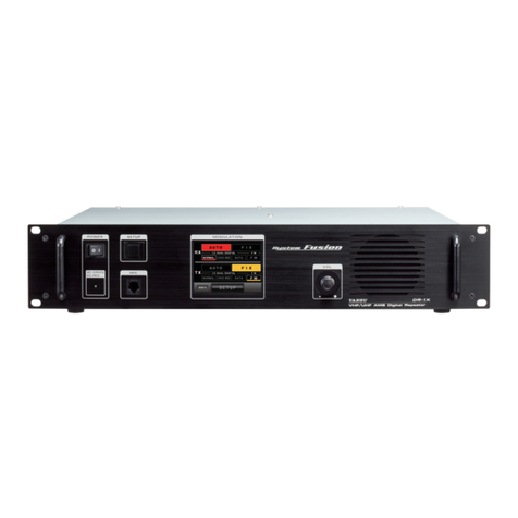
Yaesu DR-1X Manual

Specications
Exploded View & Miscellaneous Parts
Block Diagram
Connection Diagram
Alignment
Board Unit (Schematics, Layouts & Parts)
TX-MAIN Unit
PANEL-1 Unit
PANEL-2 Unit
JACK Unit
RX-MAIN Unit
RELAY-Unit
VR Unit
FILTER-Unit
DSP Unit
144/430 MHz 50 W VHF/UHF AMS DIGITAL REPEATER
DR-1X/XE
C4FM FDMA/FM
Introduction
This manual provides the technical information necessary for servicing the DR-1X/XE 144/430 MHz 50 W VHF/UHF AMS DIGI-
TAL REPEATER.
Servicing this equipment requires expertise in handing surface-mount chip components. Attempts by non-qualied persons to
service this equipment may result in permanent damage not covered by the warranty, and may be illegal in some countries.
Two PCB layout diagrams provided for each double-sided board in this transceiver. Each side of the board is referred to by the
type of the majority of components installed on that side ("Side A" or "Side B"). In most cases one side has only chip compo-
nents, and the other has either a mixture of both chip and leaded components (trimmers, coils, electrolytic capacitors, ICs, etc.),
or leaded components only.
While we believe the information in this manual to be correct, YAESU assumes no liability for damage that may occur as a result
of typographical or other errors that may be present. Your cooperation in pointing out any inconsistencies in the technical infor-
mation would be appreciated.
Important Note
1) This transceiver was assembled using Pb (lead) free solder, based on the RoHS specication.
Only lead-free solder (Alloy Composition: Sn-3.0Ag-0.5Cu) should be used for repairs performed on this apparatus. The solder stat-
ed above utilizes the alloy composition required for compliance with the lead-free specication, and any solder with the above alloy
composition may be used.
2) Risk of explosion if battery is replaced by an incorrect type. Dispose of used batteries according to the instructions.
Contents
Technical Supplement

DR-1X/XE Technical Supplement
Specications
SPECIFICATIONS-1
General
Frequency Range: 144 to 146 MHz, 430 to 440 MHz
144 to 148 MHz, 430 to 450 MHz
Channel Steps: 5 / 6.25 kHz
Emission type: F1D, F2A, F2D, F3E, F7W
Frequency Stability: ±2.5 ppm (-4 °F to +140 °F [–20 °C to +60 °C])
Antenna Impedance: 50 Ohms
Supply Voltage: AC 100 to 240 V (DR-1X, except AUS version)
DC 11.7 to 15.8 V , negative ground
Current Consumption: AC: 2 A (max) (@ 117 V Input) (DR-1X, except AUS version)
DC: 1.5 A (receive)
10 A (50 W TX, 144 MHz band)
10 A (50 W TX, 430 MHz band)
Operating Temperature: DR-1X: -4 °F to +140 °F (–20 °C to +60 °C)
DR-1XE: –20 °C to +55 °C
Dimensions (WxHxD): 19” x 3.5” x 15” (482 x 88 x 380 mm)
Weight (Approx.): DR-1X: 22.05 lbs (10 kg)
DR-1XE: 8.8 kg
Transmier
RF ower Output: 50 / 20 / 5 W
Modulation Types: F1D, F2A, F2D, F3E Variable Reactance Modulation
F7W 4FSK (C4FM)
Spurious Emission: At least 60 dB below
Receiver
Circuit Type: Double conversion Super-heterodyne
Intermediate Frequencies: 1st: 47.25 MHz
2nd: 450 kHz
Receiver Sensitivity: 0.3 μV (Digital 2 m/70 cm) BER 1 %
0.2 μV (FM 2 m/70 cm) 12 dB SINARD
Thereisnospecicationforfrequencyrangesnotlisted.
Adjacent Channel Selectivity: Beerthan65dBTYP(20kHzoset)
Selectivity: FM12kHz/35kHz(−6dB/−60dB)
Intermodulation: Beerthan65dBTYP(20/40kHzoset)
Audio Output: 4W(4Ω,THD10%,13.8V;internalspeaker)
Specications are subject to change, in the interest of technical improvement, without notice or obligation,
and are guaranteed only within the amateur bands.

DR-1X/XE Technical Supplement
Exploded View-1
REF. YAESU P/N Description Qty.
①RA1558800 GASKET(60x12) 1
②RA1558900 GASKET(35x12) 2
③RA1559000 GASKET(15x12) 1
④RA1559100 GASKET(5x12) 1
⑤U04515001 SEMS SCREW HSM5X15 4
⑥U03206001 SEMS SCREW ASM2.6X6 6
⑦U03305002 PAN HEAD SCREW ASM3X5NI 4
⑧S5000335 SPACER QBSB2610 4
⑨U20308002 BINDING HEAD SCREW M3X8NI 15
⑩U30308007 FLAT HEAD SCREW M3X8B 4
⑪U9900296 TORX SCREW TRX SLIM HEAD M4X6 3
YAESU P/N Description
Q0000143 FUSE 0218 005.MXP 5A
Q0000075 BLADE FUSE ATC 15A
T9017882 (for USA) AC-CABLE 117V3WP YFC-18K
T9013285 (for EXP) AC CABLE 220V 3W YFC-14K
T9027285 (for CHN, Lot. -6) AC CABLE CHN YP-03/YC-12 1830MM
T9027385 (for CHN, Lot. 7-) AC CABLE CHN VM0723-VM0725 1830MM
T9026115 DC CABLE 02P 15A UL
T9101621 CT CABLE SCU-20
S4000052 CASE LEG FF-004-AR791
N4090163
PUSH SWITCH 8W1021-N-Z
RA1339400 (Lot. 1-4)
RA133940A (Lot. 5-)
VOLUME KNOB (ASSY)
N2090065
ROCKER SWITCH SDDJE30300
RA1550100
DOUBLE FACE(LG)
RA1550000
LIGHT GUIDE
RA1340000
LCD SPACER (A)
RA154610A
TOP CASE
Q7000649
LCD MODULE UMSH-8513MD-T
JACK-UNIT
T9207602
T9207600
T9207601
T9207600
PANEL-1-UNIT
PANEL-2-UNIT
S5000241
HANDLE THA-216-02
(2 pcs)
RA154520B
SP NET
RA1544900 (Lot. 1)
RA154490A (Lot. 2-4)
RA154490B (Lot. 5-)
FRONT PANEL
⑤
⑤
⑩
⑩
⑩
⑩
⑤
⑤
⑦
⑦
⑦
⑦
⑥
⑥
⑪
⑪
⑪
⑥
⑥
⑥
⑥
②
③
④
①
⑨
⑨
⑨
⑨
⑨
⑨
⑨
⑨
⑨
⑨
⑨
⑨
⑨
⑨
⑨
⑧
⑧⑧
⑧
RA1545000
PANEL FRAME
RA1545100
SP HOLDER
RA1545300 (Lot. 1)
RA154530A (Lot. 2-3)
RA154530B (Lot. 4)
RA154530C (Lot. 5-)
MAIN FRAME
M4090167
SPEAKER 77F-F3205 12W/4-OHM
RA0962400
DOUBLE FACE (SP)
VR-UNIT
w/ *1, *2
*1
*2
Exploded View

DR-1X/XE Technical Supplement
Exploded View-2
REF. YAESU P/N Description Qty.
①U9900020 HEX HEAD BOLT HSM4X8B 4
②U04306002 SEMS SCREW HSM3X6NI 12
③U04330007 SEMS SCREW HSM3X30B 4
④U20308002 BINDING HEAD SCREW M3X8NI 2
⑤U66300002 FLANGE NUT N3NI 2
⑥S4000052 CASE LEG FF-004-AR791 4
RA1545700
BRACKET(TX) (2 pcs)
T9207594
T9101626
RA155920A
HOLDER(HEATSINK)
RA1559300
ThermalConductivePad
S5000336
HEAT SINK EG(138)L=10
T9207482
T9207483 (for CE version)
M2090053
FAN EC4010H12E
M2090052
FAN ASFN60371001
RA1546000
MOTOR HOLDER
RA1550200
BLIND SHEET
RA156490A
HOLDER(FAN60)
RA1580100
PAD(195x40)
⑤
⑤
⑥
⑥
⑥
⑥
②
②
②
②
②
②
②
②
②
②
②
②
③
③
③
③
④
④
①
①
①
①
Exploded View

DR-1X/XE Technical Supplement
Exploded View-3
REF. YAESU P/N Description Qty.
①U52415002 HEX HEAD BOLT M4X15NI 1
②U72004002 TOOTHED LOCK WASHER OW4NI 1
③U70005002 PLAIN WASHER FW5NI 2
④U20308002 BINDING HEAD SCREW M3X8NI 2
⑤U66300002 FLANGE NUT N3NI 2
⑥S5000268 SPACER QBSB310 4
⑦U04306002 SEMS SCREW HSM3X6NI 8
⑧U9900020 HEX HEAD BOLT HSM4X8B 4
⑤
⑤
⑥
⑦
⑦
⑦
⑦
⑦
⑦
⑧⑧
⑧
⑧
⑦⑦
⑥
⑥
②
③③
④
④
①
P2000067 (for INTERNAL PS)
FUSE HOLDER MF500
T9207596A (Lot. 1)
T9207596B (Lot. 2-)
RA154560A
FRAME
RA156650B
SHIELD CASE COVER
RA1545800
BRACKET(RX)
(2 pcs)
T9207597 (for INTERNAL PS)
T9207614 (for INTERNAL PS)
T9101625
Exploded View

DR-1X/XE Technical Supplement
Exploded View-4
②
②
③
③
③
③
③
③
④
④
④
④
④
④
①
①
T9207609
(for INTERNAL PS)
T9207612
T9207603
Q7000671 (for INTERNAL PS)
T9207615 (for INTERNAL PS)
T9207595 (for INTERNAL PS)
T9207598
RELAY-UNIT
REF. YAESU P/N Description Qty.
①U20406002 BINDING HEAD SCREW M4X6NI 2
②U72004002 TOOTHED LOCK WASHER OW4NI 2
③U9900296 TORX SCREW TRX SLIM HEAD M4X6 6
④U04306002 SEMS SCREW HSM3X6NI 6
L9190184 (for INTERNAL PS)
CORE ZCAT1325-0530A-BK
RA1562300
PLATE(D-SUB)
Exploded View

DR-1X/XE Technical Supplement
Exploded View-5
⑤
⑤
⑤
⑤
②
②
③
③
④④④
④
④
④
④
④
④
④
④
④
④
④④
①
①
①
①
RA1565000 (Lot. 1-2)
RA156500A (Lot. 3-)
CASE (H043U)
RA1406600
GROUND PLATE(FET)
RA1406500
SHIELD CASE COVER
RA1577800
ThermalConductivePad
RA140640A
FRONT COVER
REF. YAESU P/N Description Qty.
①U31208007 OVAL HEAD SCREW M2.6X8B 4
②U20205007 BINDING HEAD SCREW M2.6X5B 2
③U20308002 BINDING HEAD SCREW M3X8NI 2
④U44308001 PAN HEAD TAPTITE-B M3X8 15
⑤U03310002 SEMS SCREW ASM3X10NI 4
T9207610
T9101625
RA1565900
ThermalConductivePad
P1090547
CONNECTOR
S5000236
LUG WASHER FOR MDR-2
RA0438700
RUBBER
RA1316600
PLATE(FET)
RA026680C
CHASSIS
Exploded View

DR-1X/XE Technical Supplement
Exploded View-6
③
③
④
④
④
④
④
④
④
④
④
④
④
④
④④
①
①
①
①
RA1198800
PORON SHEET
RA1406700
SPONGE RUBBER(VU)
RA1566000
ThermalConductivePad
CQ0419000
RX CASE ASSY
P1090547
CONNECTOR
S5000236
LUG WASHER FOR MDR-2
RA026680C
CHASSIS
T9207613
T9207607
REF. YAESU P/N Description Qty.
①U31208007 OVAL HEAD SCREW M2.6X8B 4
②U20205007 BINDING HEAD SCREW M2.6X5B 2
③U20308002 BINDING HEAD SCREW M3X8NI 2
④U44308001 PAN HEAD TAPTITE-B M3X8 14
②
②
RA140640A
FRONT COVER
RA0438700
RUBBER
T9101625
Exploded View

DR-1X/XE Technical Supplement
BLOCK DIAGRAM-1
Block Diagram

DR-1X/XE Technical Supplement
CONNECTION DIAGRAM-1
Connection Diagram

DR-1X/XE Technical Supplement
Alignment
ALIGNMENT-1
Introduction and Precautions
TheDR-1X/DR-1XEhasbeencarefullyalignedat
thefactoryforperformanceacrossthespecified
amateurbands.Realignmentshouldtherefore
notbenecessaryexceptintheeventofacompo-
nentfailure.Allcomponentreplacementandser-
viceshouldbeperformedonlybyanauthorized
YAESUrepresentative,orthewarrantypolicymay
be voided.
Thefollowingprocedurescoverthesometimescrit-
ical and tedious adjustments that are not normally
requiredoncethetransceiverhasleftthefactory.
However,ifdamageoccursandsomepartsarere-
placed,realignment maybe required.If a sudden
problem occurs during normal operation, it is like-
lyduetocomponentfailure;realignmentshould
notbedoneuntilafterthefaultycomponenthas
been replaced.
Werecommendthatservicingbeperformedonly
byauthorizedYAESUservicetechnicians,whoare
experiencedwiththecircuitryandfullyequipped
forrepairandalignment.Therefore,ifafaultis
suspected,contactthedealerfromwhomthetrans-
ceiverwaspurchasedforinstructionsregardingre-
pair.AuthorizedYAESUservicetechniciansrealign
allcircuitsandmakecompleteperformancechecks
toensurecompliancewithfactoryspecifications
aerreplacinganyfaultycomponents.
Thosewhodoundertakeanyofthefollowing
alignments are cautioned to proceed at their own
risk.Problemscausedbyunauthorizedaemptsat
realignment are not covered by the warranty pol-
icy.Also,YAESUmustreservetherighttochange
circuitsandalignmentproceduresintheinterestof
improvedperformance,withoutnotifyingowners.
Under no circumstances should any alignment be
attemptedunlessthenormalfunctionandopera-
tionofthetransceiverareclearlyunderstood,the
causeofthemalfunctionhasbeenclearlypinpoint-
edandanyfaultycomponentsreplaced,andthe
needforrealignmentdeterminedtobeabsolutely
necessary.
Required Test Equipment
RF Signal Generator with calibrated output lev-
el at 1 GHz
Deviation Meter (linear detector)
In-lineWameterwith5%accuracyat1GHz
50-ohm, 100-W RF Dummy Load
8-ohm AF Dummy Load
RegulatedDCPowerSupplyadjustablefrom
11.5 to 16 V DC, 15 A
FrequencyCounter:0.2-ppmaccuracyat
1 GHz
AF Signal Generator
AC Voltmeter
DC Voltmeter: high impedance
VHF/UHF Sampling Coupler
SINAD Meter
Important Notice
Do not adjust the alignment menus that are
not mentioned in this manual.

DR-1X/XE Technical Supplement
Alignment
ALIGNMENT-2
Alignment Preparation & Precautions
A 100-W RF dummy load and in-line wattmeter
must be connected to the main antenna jack in all
proceduresthatcallfortransmission;alignment
isnotpossiblewithanantenna.Aftercomplet-
ingonestep,readthe nextsteptoseeifthesame
testequipmentisrequired.Ifnot,removethetest
equipment(exceptdummyloadandwattmeter,
ifconnected)beforeproceeding.Correctalign-
mentrequiresthetransceiverandtestequipment
be maintained at a constant ambient temperature
between 68 ~ 86 °F (20 ~ 30 °C). When the trans-
ceiverisbroughtintotheshopfromhotorcoldair,
it should be allowed some time to come to room
temperaturebeforealignment.Wheneverpossible,
alignments should be made with oscillator shields
andcircuitboardsrmlyaxedinplace.Also,the
testequipmentmustbethoroughlywarmedupbe-
forebeginning.
Note: Signal levels in dB referred to in the alignment
procedure are based on 0 dBμ=0.5 μV (closed circuit).
Internal System Alignment Routine
This uses a programmed routine in the transceiver
whichsimpliesmanypreviouslycomplexdiscrete
componentseingsandadjustmentswithdigital-
ly-controlledseingsviaMicrophonebuons.
To enter the Alignment mode:
1. ConnectthePANEL-UNITtoTX-MAIN-UNIT
and RX-MAIN-UNIT.
2. Pressandholdinthe[D(X)] and [DISP)] keys
while turning the transceiver on.
3. The transceiver is now in the "Transceiver
mode".
4. Pressandholdinthe[POWER(LOCK)]keyfor
two seconds.
5. Pressandholdinthe[F(MW)] and [GM)] keys
while turning the transceiver on.
6. Pressthe[POWER(LOCK)] key.
"LOCK" will appear in the display.
7. PressthekeysoftheMicrophoneinthefollow-
ingsequence.
[0] à [3] à [4] à [0] à [3] à [4]
8. Pressthe[POWER(LOCK)] key.
"UNLOCK" will appear in the display.
9. The transceiver is now in the "Alignment
mode".
MIC Jack

DR-1X/XE Technical Supplement
Alignment
ALIGNMENT-3
VCO VCV Adjustment
Connect the DC voltmeter to TP1503 (TX-MAIN-
UNIT) and TP5502(RX-MAIN-UNIT).Referring
tothetablebelow,turnthetransceivertoeachfre-
quencylisted.Conrmthat the correctvoltageis
present,oradjustthelistedseingfortherequired
voltage.
TX-MAIN-UNIT
Tune to: TX/RX for
440.05 MHz TX 2.1 ± 0.4 V
146.05 MHz TX 2.0 ± 0.4 V
RX-MAIN-UNIT
Tune to: TX/RX for
440.05 MHz RX 2.6 ± 0.4 V
146.05 MHz RX 1.2 ± 0.4 V
DC Voltmeter
1. Set the power supply voltage to 13.8 V.
2. Pressthe [P1]keyofthe Microphone to set the
alignment menu Item to "Adj 10 BAT".
3. Pressthe [P3]keyofthe Microphone, to save
thenewseing.
TP5502TP1503
TX-MAIN-UNIT RX-MAIN-UNIT

DR-1X/XE Technical Supplement
Alignment
ALIGNMENT-4
TX Power Adjustment
1. Pressthe [P1]keyofthe Microphone to set the
alignment menu Item to "Adj 02 PWR".
2. SettheTX-MAIN-UNITfrequencyto440.050
MHz.
3. Pressthe[F(MW)] key, then press the [Tx PWR]
to select "LO".
4. Pressthe[F(MW)] key.
5. PressthePTTswitchtoactivatethetransmier,
adjust the DIALknobsothatRFPowerMeter
reading is 5 W (± 0.5 W).
6. Pressthe [P2]keyofthe Microphone to set the
alignment menu Item to "Adj 02 DRV".
7. Adjust the DIAL knob (Band B) to set the DRV
to "9A".
8. Pressthe [P2]keyofthe Microphone to set the
alignment menu Item to "Adj 02 PWR".
9. Pressthe[F(MW)] key, then press the [Tx PWR]
to select "MD".
10. Pressthe[F(MW)] key.
11. PressthePTTswitchtoactivatethetransmier,
adjust the DIALknobsothatRFPowerMeter
reading is 20 W (± 0.5 W).
12. Pressthe [P2]keyofthe Microphone to set the
alignment menu Item to "Adj 02 DRV".
13. Adjust the DIAL knob to set the DRV to "B0".
14. Pressthe [P2]keyofthe Microphone to set the
alignment menu Item to "Adj 02 PWR".
15. Pressthe[F(MW)] key, then press the [Tx PWR]
to select "HI".
16. Pressthe[F(MW)] key.
17. PressthePTTswitchtoactivatethetransmier,
adjust the DIALknobsothatRFPowerMeter
reading is 50 W (± 0.5 W).
18. Pressthe [P2]keyofthe Microphone to set the
alignment menu Item to "Adj 02 DRV".
19. Adjust the DIAL knob to set the DRV to "D0".
20. Pressthe [P2]keyofthe Microphone to set the
alignment menu Item to "Adj 02 PWR".
21. SettheTX-MAIN-UNITfrequencyto146.050
MHz.
22. Pressthe[F(MW)] key, then press the [Tx PWR]
to select "LO".
23. Pressthe[F(MW)] key.
24. PressthePTTswitchtoactivatethetransmier,
adjust the DIALknobsothatRFPowerMeter
reading is 5 W (± 0.5 W).
25. Pressthe [P2]keyofthe Microphone to set the
alignment menu Item to "Adj 02 DRV".
26. Adjust the DIAL knob to set the DRV to "CF".
27. Pressthe [P2]keyofthe Microphone to set the
alignment menu Item to "Adj 02 PWR".
28. Pressthe[F(MW)] key, then press the [Tx PWR]
to select "MD".
29. Pressthe[F(MW)] key.
30. PressthePTTswitchtoactivatethetransmier,
adjust the DIALknobsothatRFPowerMeter
reading is 20 W (± 0.5 W).
31. Pressthe [P2]keyofthe Microphone to set the
alignment menu Item to "Adj 02 DRV".
32. Adjust the DIAL knob to set the DRV to "DA".
33. Pressthe [P2]keyofthe Microphone to set the
alignment menu Item to "Adj 02 PWR".
34. Pressthe[F(MW)] key, then press the [Tx PWR]
to select "HI".
35. Pressthe[F(MW)] key.
36. PressthePTTswitchtoactivatethetransmier,
adjust the DIALknobsothatRFPowerMeter
reading is 50 W (± 0.5 W).
37. Pressthe [P2]keyofthe Microphone to set the
alignment menu Item to "Adj 02 DRV".
38. Adjust the DIAL knob to set the DRV to "EF".
39. Pressthe [P2]keyofthe Microphone to set the
alignment menu Item to "Adj 02 PWR".

DR-1X/XE Technical Supplement
Alignment
ALIGNMENT-5
PLL Reference Frequency Adjustmen
t
1. Pressthe [P1]keyofthe Microphone to set the
alignment menu Item to "Adj 00 REF/A".
2. SettheTX-MAIN-UNITfrequencyto435.050
MHz.
3. Pressthe[F(MW)] key, then press the [Tx PWR]
to select "LO".
4. Pressthe[F(MW)] key.
5. PressthePTTswitchtoactivatethetransmier,
adjust the DIALknob,ifnecessary,sothecount-
erfrequencyiswithin100Hzof435.050MHz.
6. SettheRX-MAIN-UNITfrequencyto435.050
MHz.
7. Pressthe [P1]keyofthe Microphone to set the
alignment menu Item to "Adj 00 REF/A".
8. Connectthefrequencycounterfedthroughthe
0.001μF capactor to the TP5501.
9. Adjust adjust the DIAL knob, as needed, so that
thecounterfrequencyreadingis390.200MHz
(±100Hz).
10. Pressthe [P2]keyofthe Microphone to set the
alignment menu Item to "Adj 00 REF/B".
11. Connectthefrequencycounterfedthrough
the0.001μF capactor to the TP5509.
12. Adjust adjust the DIAL knob, as needed, so that
thecounterfrequencyreadingis387.800MHz
(±100Hz).
TP5501
TP5509
RX-MAIN-UNIT

DR-1X/XE Technical Supplement
Alignment
ALIGNMENT-6
RF Front-end Tuning
1. Connect the DC voltmeter to TP5001 (BAND A)
and TP5002 (BAND B) on the RX-MAIN unit,
theninjecta439.050MHzsignalatalevelof+10
dBμV (with 1kHz modulation ± 3.5 kHz devia-
tion)fromtheRFsignalgenerator.
2. SettheRX-MAIN-UNITfrequencyto439.050
MHz.
3. Pressthe [P1]keyofthe Microphone to set the
alignment menu Item to "Adj 01 TUN/A".
4. Adjust the DIALknob for maximum deection
on the DC Voltmeter and then turn the dialin
theoppositedirectionuntilthemeterdeection
drops slightly lower than maximum.
5. Set the RX-MAIN-UNIT and RF signal genera-
torfrequencyto145.050MHz.
6. Adjust the DIALknob for maximum deection
on the DC Voltmeter and then turn the dialin
theoppositedirectionuntilthemeterdeection
drops slightly lower than maximum.
7. SettheRFsignalgeneratorfrequencyto
439.050MHz.
8. SettheRX-MAIN-UNITfrequencyto439.050
MHzoftheBandB.
9. Pressthe [P2]keyofthe Microphone to set the
alignment menu Item to "Adj 01 TUN/B".
10. Adjust the DIAL knobfor maximumdeection
on the DC Voltmeter and then turn the dialin
theoppositedirectionuntilthemeterdeection
drops slightly lower than maximum.
11. SetthetransceiverandRFsignalgeneratorfre-
quencyto145.050MHz.
12. Adjust the DIAL knobfor maximumdeection
on the DC Voltmeter and then turn the dialin
theoppositedirectionuntilthemeterdeection
drops slightly lower than maximum.
TP5002TP5001
RX-MAIN-UNIT

DR-1X/XE Technical Supplement
Alignment
ALIGNMENT-7
Squelch Threshold Level
1. Set the RF signal generator to 440.050 MHz. Set
thegeneratorfor±3.5kHzdeviationofa1kHz
modulation tone, and set the RF output level
fromthesignalgeneratorto-10dBμV.
2. SettheRX-MAIN-UNITfrequencyto440.050
MHz.
3. Pressthe[D(X)] key to select "FM".
4. Pressthe [P1]keyofthe Microphone to set the
alignment menu Item to "Adj 09 SQL/A".
5. Pressthe [P4] key tosavethenewseing.
6. Increasetheoutputlevelofthesignalgenera-
torup to -3 dBμV.
7. Pressthe [P3] key tosavethenewseing.
8. Set the RX-MAIN-UNIT and RF signal genera-
torfrequencyto146.050MHz.
9. Increasetheoutputlevelofthesignalgenera-
torup to -10 dBμV.
10. Pressthe [P4] key tosavethenewseing.
11. Increasetheoutputlevelofthesignalgenera-
torup to -3 dBμV.
12. Pressthe [P3] key tosavethenewseing.
13. Pressthe [P2]keyofthe Microphone to set the
alignment menu Item to "Adj 09 SQL/B".
14. Set the RF signal generator to 440.050 MHz. Set
thegeneratorfor±3.5kHzdeviationofa1kHz
modulation tone, and set the RF output level
fromthesignalgeneratorto-10dBμV.
15. SettheRX-MAIN-UNITfrequencyto440.050
MHz.
16. Pressthe[D(X)] key to select "FM".
17. Pressthe [P4] key tosavethenewseing.
18. Increasetheoutputlevelofthesignalgenera-
torup to -3 dBμV.
19. Pressthe [P3] key tosavethenewseing.
20. SetthetransceiverandRFsignalgeneratorfre-
quencyto146.050MHz.
21. Increasetheoutputlevelofthesignalgenera-
torup to -10 dBμV.
22. Pressthe [P4] key tosavethenewseing.
23. Increasetheoutputlevelofthesignalgenera-
torup to -3 dBμV.
24. Pressthe [P3] key tosavethenewseing.
S-Meter Calibration
1. Set the RF signal generator to 440.050 MHz. Set
thegeneratorfor±3.5kHzdeviationofa1kHz
modulation tone, and set the RF output level
fromthesignalgeneratorto-5dBμV.
2. SettheRX-MAIN-UNITfrequencyto440.050
MHz.
3. Pressthe[D(X)] key to select "FM".
4. Pressthe [P1]keyofthe Microphone to set the
alignment menu Item to "Adj 08 SM/A".
5. Pressthe [P4] key tosavethenewseing.
6. Increasetheoutputlevelofthesignalgenera-
torup to +23 dBμV.
7. Pressthe [P3] key tosavethenewseing.
8. Set the RX-MAIN-UNIT and RF signal genera-
torfrequencyto146.050MHz.
9. Increasetheoutputlevelofthesignalgenera-
torup to -5 dBμV.
10. Pressthe [P4] key tosavethenewseing.
11. Increasetheoutputlevelofthesignalgenera-
torup to +23 dBμV.
12. Pressthe [P3] key tosavethenewseing.
13. Pressthe [P2]keyofthe Microphone to set the
alignment menu Item to "Adj 09 SM/B".
14. Set the RF signal generator to 440.050 MHz. Set
thegeneratorfor±3.5kHzdeviationofa1kHz
modulation tone, and set the RF output level
fromthesignalgeneratorto-5dBμV.
15. SettheRX-MAIN-UNITfrequencyto440.050
MHz.
16. Pressthe[D(X)] key to select "FM".
17. Pressthe [P4] key tosavethenewseing.
18. Increasetheoutputlevelofthesignalgenera-
torup to +23 dBμV.
19. Pressthe [P3] key tosavethenewseing.
20. Set the RX-MAIN-UNIT and RF signal genera-
torfrequencyto146.050MHz.
21. Increasetheoutputlevelofthesignalgenera-
torup to -5 dBμV.
22. Pressthe [P4] key tosavethenewseing.
23. Increasetheoutputlevelofthesignalgenera-
torup to +23 dBμV.
24. Pressthe [P3] key tosavethenewseing.

DR-1X/XE Technical Supplement
Alignment
ALIGNMENT-8
TX Deviation
1. Injecta1kHz,80mVsignalfromtheAudio
Generator.
2. SettheTX-MAIN-UNITfrequencyto440.050
MHz.
3. Pressthe[F(MW)] key, then press the [Tx PWR]
to select "LO".
4. Pressthe[F(MW)] key.
5. Pressthe [P1]keyofthe Microphone to set the
alignment menu Item to "Adj 03 DEV".
6. PressthePTTswitchtoactivatethetransmier,
adjust the DIAL knob so that the Deviation Me-
ter reading is 4.5 kHz (±0.2 kHz) (USA Version:
4.2 kHz (±0.2 kHz).
7. SettheTX-MAIN-UNITfrequencyto146.050
MHz.
8. Pressthe[F(MW)] key, then press the [Tx PWR]
to select "LO".
9. PressthePTTswitchtoactivatethetransmier,
adjust the DIAL knob so that the DeviationMe-
ter reading is 4.5 kHz (±0.2 kHz) (USA Version:
4.2 kHz (±0.2 kHz).
Digital TX Deviation
1. Injecta1kHz,80mVsignalfromtheAudio
Generator.
2. SettheTX-MAIN-UNITfrequencyto440.050
MHz.
3. Pressthe[F(MW)] key, then press the [Tx PWR]
to select "LO".
4. Pressthe[F(MW)] key.
5. Pressthe [P1]keyofthe Microphone to set the
alignment menu Item to "Adj 04 MOD".
6. Pressthe [P2]keyofthe Microphone to set the
alignment menu Item to "Adj 04 MIX".
7. PressthePTTswitchtoactivatethetransmier,
adjust the DIAL knob so that the Deviation Me-
ter reading is 4.5 kHz (±0.2 kHz).
8. SettheTX-MAIN-UNITfrequencyto146.050
MHz.
9. Pressthe[F(MW)] key, then press the [Tx PWR]
to select "LO".
10. Pressthe[F(MW)] key.
11. PressthePTTswitchtoactivatethetransmier,
adjust the DIAL knob so that the DeviationMe-
ter reading is 4.5 kHz (±0.2 kHz) (USA Version:
4.2 kHz (±0.2 kHz).
DCS TX Deviation
1. SettheTX-MAIN-UNITfrequencyto440.050
MHz.
2. Pressthe[F(MW)] key, then press the [Tx PWR]
to select "LO".
3. Press the [SQL] to select "D-TRX".
4. Pressthe[F(MW)] key.
5. Pressthe [P1]keyofthe Microphone to set the
alignment menu Item to "Adj 05 DCS".
6. PressthePTTswitchtoactivatethetransmier,
adjust the DIAL knob so that the Deviation Me-
ter reading is 0.60 kHz ~ 0.80 kHz.
7. SettheTX-MAIN-UNITfrequencyto146.050
MHz.
8. Pressthe[F(MW)] key, then press the [Tx PWR]
to select "LO".
9. Pressthe[F(MW)] key.
10. PressthePTTswitchtoactivatethetransmier,
adjust the DIAL knob so that the Deviation Me-
ter reading is 0.60 kHz ~ 0.80 kHz.
CTCSS TX Deviation
1. SettheTX-MAIN-UNITfrequencyto440.050
MHz.
2. Pressthe[F(MW)] key, then press the [Tx PWR]
to select "LO".
3. Press the [SQL] to select "T-TRX".
4. Pressthe[F(MW)] key.
5. Pressthe [P1]keyofthe Microphone to set the
alignment menu Item to "Adj 06 CTC".
6. PressthePTTswitchtoactivatethetransmier,
adjust the DIAL knob so that the Deviation Me-
ter reading is 0.65 kHz ~ 0.75 kHz.
7. SettheTX-MAIN-UNITfrequencyto146.050
MHz.
8. Pressthe[F(MW)] key, then press the [Tx PWR]
to select "LO".
9. Pressthe[F(MW)] key.
10. PressthePTTswitchtoactivatethetransmier,
adjust the DIAL knob so that the Deviation Me-
ter reading is 0.65 kHz ~ 0.75 kHz.

DR-1X/XE Technical Supplement
Alignment
ALIGNMENT-9
Center Meter Calibration
1. Set the RF signal generator to 440.050 MHz. Set
thegeneratorfor±3.5kHzdeviationofa1kHz
modulation tone, and set the RF output level
fromthesignalgeneratorto+10dBμV.
2. SettheRX-MAIN-UNITfrequencyto440.050
MHz.
3. Pressthe[D(X)] key to select "FM".
4. Pressthe [P1]keyofthe Microphone to set the
alignment menu Item to "Adj 07 CTR/A".
5. Pressthe [P3] key tosavethenewseing.
6. Setthetransceiverfrequencyto440.050MHzof
the Band B.
7. Pressthe[D(X)] key to select "FM".
8. Pressthe [P2]keyofthe Microphone to set the
alignment menu Item to "Adj 07 CTR/B".
9. Pressthe [P3] key tosavethenewseing.
To close the alignment mode, just turn the power
obypressingandholding the[POWER(LOCK)]
switchfortwoseconds.
Pressandholdinthe[D(X)] and [DISP)] keys
while turning the transceiver on.
The transceiver is now in the "Repeater mode".

DR-1X/XE Technical Supplement
TX MAIN-1
TX MAIN Unit
Circuit Diagram
Other manuals for DR-1X
4
This manual suits for next models
1
Table of contents
Other Yaesu Repeater manuals

Yaesu
Yaesu WIRES-X FT3D User manual

Yaesu
Yaesu DR-1X User manual

Yaesu
Yaesu WIRES-X HRI-200 User manual

Yaesu
Yaesu DR-1X User manual

Yaesu
Yaesu WIRES-X TM-400FT5D Installation and operation manual

Yaesu
Yaesu VXR-7000U User manual

Yaesu
Yaesu DR-1X User manual

Yaesu
Yaesu C4FM User manual

Yaesu
Yaesu DR-1X User manual

Yaesu
Yaesu DR-2X User manual