Yaesu DR-2X Manual

Chelsea Yaesu DR-2X Repeater Setup
Wesley Cardone, N8QM
July 3, 2022
Security of Remote Commands
The Yaesu DR-2X repeater has two modes of operation: Analog FM (DTMF); and Digital (C4FM). Remote
commands may be given the repeater over the air via either of these two modes. However, there are
distinctions between them.
DIGITAL:
The digital mode of operation offers bulletproof security in that any remote commands can only
come from transceivers registered with the repeater.
At the factory, each C4FM transmitter is given a unique digital key which it, and only it, possesses in
all the world. Any one Yaesu C4FM transmitter can be registered (up to 30 per repeater) with any
one DR-2X repeater. This means that bullet-proof security exists in protecting the repeater from
malicious threats.
In addition to this security, operating in the C4FM mode includes all of the security belonging to
remote programming in Analog FM mode, described below.
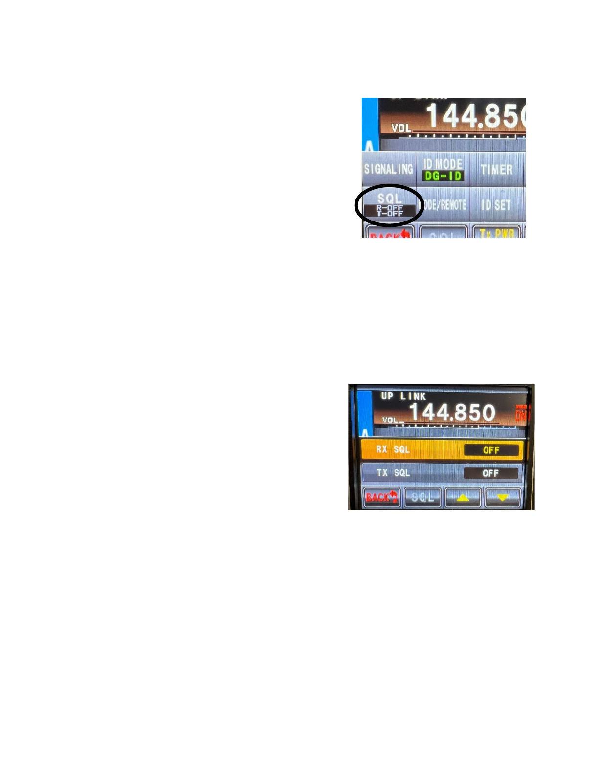
ANALOG FM:
The DR-2X repeater may be programmed to operate in either a single-channel or dual-channel
mode. The Chelsea WD8IEL repeater is being operated in the single-channel mode which makes the
repeater’s second channel available for dedicated remote programming. That is, remote
programming coming to the repeater over the air does not need to share the FCC designated
repeater frequency assignment of 145.450 MHz. Any FCC amateur allocated frequency may be used
for remote programming from whether the 2 meters band (144-148 MHz) or the 70 cm (420-
450 MHz) band.
As an additional layer of protection, the repeater will only receive on that second frequency and
cannot send. Someone trying all the frequencies would have no means of feedback from the
repeater to indicate success. There are some remote functions which cause an output on the actual
repeater assigned frequency but there would be very much labor in a brute-force approach to
finding the command frequency.
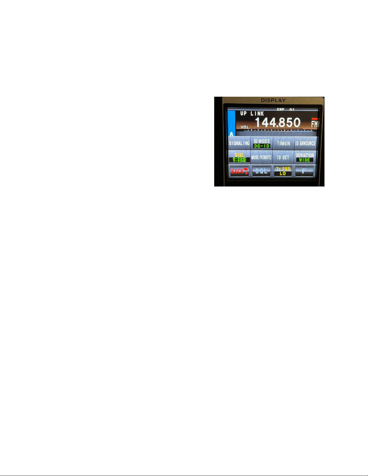
To add additional complexity to a brute-force approach, there are 64 different PL tones that would
have to be worked through with each frequency. In the paragraph above it was stated that there
would be “very much labor.” Adding 64 PL tones would make the labor prohibitive even for a
youngster working from his parent’s basement.
What the person attempting to crack the repeater would need to radically reduce the labor would
be a known time when remote programming was being sent over the air. If the prankster knew a
precise time when codes were to be sent to the repeater, he could be scanning both 2 meters and
70 cm for any activity. With a little luck he might light on the code transmission frequency value.
Once he knows the exact frequency used, he would then need to make sure he had identified the PL
tone which is doable but laborious.

Chelsea Yaesu DR-2X Repeater Setup
Wesley Cardone, N8QM
July 3, 2022
Assuming anyone globally (but within range of the repeater) had obtained the exact B-channel
repeater frequency and PL tone, he would then have as much control over the repeater as we do.
There is one additional layer of encryption that can be added. All of the remote commands have
factory assigned 4-digit integer codes. For example, the code to switch the repeater output power to
MID is 0020. All of these values are user definable. We could assign our own random numbers to
each command. The prankster would then need those codes to do anything.
PASSWORD:
At power application or after the display has timed out from programming inactivity, the display
goes blank, and a password is needed. This password does not enable operation of the repeater but
merely grants access for programming. Without this password the repeater cannot be programmed
without first restoring all of the factory settings. The password is: 0000.
Introduction
In this presentation we will start with a Yaesu DR-2X Fusion repeater (shown below) that may or may
not have some programming written into it. We are going to set it up to fulfill its role as an amateur
radio 2 meter VHF repeater which is Fusion capable. The repeater shall operate in a single-channel mode
using an uplink frequency of 144.850 MHz and a downlink frequency of 145.450 MHz. Transmit power
shall be set to MEDIUM. The FCC assigned station call sign is WD8IEL.
Program for ID and UP/Downlink
Frequencies
With power application we have the screen showing as
above in Figure 1.
Our first task will be to check on the call sign entry.
Upon power application the home screen (Figure 2) is
shown. We press the [A SETUP] button showing the
screen illustrated in Figure 3.
We can see that the repeater is already properly
programmed for the correct up and downlink
frequencies.
Figure 2 This is the "home" screen which appears at
power application.
Figure 1 This is the front-face of the Yaesu DR-2X repeater.

Chelsea Yaesu DR-2X Repeater Setup
Wesley Cardone, N8QM
July 3, 2022
We then touch the [F] button showing the next screen
(Figure 5). On that next screen we touch the [ID SET]
button revealing the screen shown in Figure 4. We can
see that the FCC assigned station call sign WD8IEL is
already properly programmed so we press the [BACK]
button three times to move to the home screen.
It should also be noted in passing that the repeater
firmware versions are shown on the Figure 3 screen.
Here we see that the installed firmware (as of June 26,
20022) of RX1.51 and DSP version 5.02. The latest
versions of that same date available from Yaseu are
Main 1.58 and DSP 5.03.
A firmware update is required when it is convenient to accomplish. In order to install a firmware update
an update cable will be required from Yaesu.
Figure 3 Correct up and downlink frequencies have been
set. For the time being the output power is set to LO but
later this will be changed to MD (medium).
Figure 5 Display having pressed the F button from the
A-Channel display.
Figure 4 This is where you can set the actual station ID
assigned by the FCC.

Chelsea Yaesu DR-2X Repeater Setup
Wesley Cardone, N8QM
July 3, 2022
Program for Single-Channel Operation
The next step is to program for our single-channel mode of operation.
There is also an option for remote control that we will program for
future use. We will get to that in a few pages.
For single-channel use the frequencies for the B-channel are
irrelevant and may be set to anything. However, in order to exercise a
remote control option at a later date, we will set the B-channel
UPLINK frequency to an unpublished frequency within the 2 meter
amateur frequency allocation. This will serve as a control frequency,
later in this document to be programmed. An acceptable transceiver
(Yaesu FTM-400D, FTM-100D and FTM-3200D) can be registered with
the repeater. From the time of registration, that transceiver becomes
unique in all the world and the repeater will listen to it for remote
instructions and programming. The repeater is capable of registering
up to 30 conforming transceivers for control purposes. In order to
remotely control the repeater, one would need to be using a
transceiver that has been previously registered with the repeater and
would need to know the uploading frequency. The frequency will not
be disclosed in this document.
At this point we need to let the repeater know what purpose the
B-channel set is to serve. This is done from the home screen. Please
see Figure 2 to know what the home screen looks like.
From the home screen, tell the repeater that the B-channel is to act
as a remote control function receiving instructions by RF from a
registered transceiver.
With the home screen showing as illustrated in Figure 2, touch the violet area for the B channel set and
the display will change to replace the thin white line separating the RX above the TX as shown in Figure
6. [B SETUP]
Figure 9 appears. The rectangular box hides the control
frequency.
Press [SQL]. Figure 8 appears. This sets the squelch level for
the B channel. Press the up and down arrows to set it to its
lowest value that is still greater than zero—1.
Press [BACK] returning to the home screen.
Figure 6 Home screen as it appears
after having touched the violate B-
channel area once. The PRI text
replaces the thin white line that had
separated the RX and TX text.
Figure 7 Home screen now shows that
the B-Channel is to be used as a control
function.
Figure 8 B Channel control screen. The
rectangular box hides the frequency used.

Chelsea Yaesu DR-2X Repeater Setup
Wesley Cardone, N8QM
July 3, 2022
The repeater now knows that the B-Channel is to be used as a
control function and will have no capability to transmit on a B-
Channel frequency. It will only listen on the B-Channel.
Set the B-Channel Listening Frequency
With the home screen showing as illustrated in Figure 7, touch
[B-SETUP] at the bottom of the screen. The repeater screen
now shows as illustrated in Figure 9.
Touch the area that is shown in Figure 9 as blurred out in this
illustration for security reasons. This will cause the repeater to
display the screen shown in Figure 10. Using the touchpad
shown, enter the frequency. Upon entry of the final figure the
repeater will enter the number and go back to the screen
shown in Figure 9.
Press the red [BACK] button once to return to the home
screen. It should look like that shown in Figure 7. There may be
some minor differences owing to the fact that when doing this
programming, the repeater had already been programmed.
Program Signaling
First we will check for the sub-audible tones. We are
registered with the Michigan coordination group to use 100 Hz
tones.
From the home screen touch [A SETUP] then [F] and then
[SIGNALING]. In the illustration shown in Figure 11, the sub-
audible tones have already been set. This is pretty much
intuitive so set them here as shown if not already so set. Press
[BACK] taking us to the uplink screen.
Figure 9 The screen shown represents the B-
Channel uplink frequency. The frequency itself
has been blurred out for security reasons.
Figure 10 This screen allows the uplink
frequency for the B-Channel to be set.
Figure 11 Programming of the sub-audible or PL
tones.

Chelsea Yaesu DR-2X Repeater Setup
Wesley Cardone, N8QM
July 3, 2022
The Squelch
Next we want to look at the squelch. First notice from the
uplink illustration of Figure 12, that both receive and transmit
tones are turned off (R-OFF and T-OFF) which is NOT correct.
One of the major benefits from using a PL tone is that
atmospheric or other electromagnetic media that occurs in
nature will not activate the repeater. It is also a guard against
other repeaters in the distant region that might otherwise
activate the repeater needlessly.
Touch the [SQL] button which causes the repeater to show the
screen illustrated in Figure 13. It is now shown that RX and TX
squelch tones are off.
Touch both RX and TX SQL one at a time until each shows “TONE.”
Press [BACK] twice (2x) taking you to…
Press [SQL] (see Figure 3). This takes you to the A-side equivalent of what we saw in the B-side Figure 8.
As we did in that earlier slide. Set the squelch to its lowest value which is still greater than zero—1.
Press [BACK] once to return to the home page.
Press [A SETUP] and [F] taking you to the uplink screen
illustrated in Figure 12. Not shown in the figure, notice now
that the Squelch button looks different reflecting the fact
that the repeater is now programmed to utilize the tones in
squelch functionality.
Press the [BACK] button two times to return to the home
screen.
Do the same programming for the B-Channel which will be
used exclusively for remote control on a special frequency.
Figure 12 Setting the squelch.
Figure 13 Here is where the repeater may be told
that it is to use sub-audio tones. The frequencies of
the tones themselves may or may not have been
already set. Those are separate functions.

Chelsea Yaesu DR-2X Repeater Setup
Wesley Cardone, N8QM
July 3, 2022
Figure 14 The repeater now knows that it is to
implement sub-audible tones. The exact audio
frequencies may or may not yet have been set.
That is a separate operation.

Chelsea Yaesu DR-2X Repeater Setup
Wesley Cardone, N8QM
July 3, 2022
Program Announcements
From the home screen press [A-SETUP] and then [F]. Then
press [ID ANNOUNCE]. The screen illustrated in Figure 15
appears.
The FCC requires station identification every ten minutes.
This can be accomplished in a variety of ways. For the time
being we are programming the repeater to output its
station identification (WD8IEL) by means of CW tones. It
would be nice to have a voice announcement but I have not
figured that out yet. CW tones will work and are warmly
accepted by the amateur community so we will go with that
mode for now.
Touch the [ANNOUNCE] button. The screen illustrated in
Figure 16 is displayed. The screen you see may differ
slightly from what is shown. What is shown is that the
repeater will transmit its station ID in a CW mode without
the use of sub-audible tones. Discarding the use of sub-
audible tones is important because that way, anyone tuned
to the repeaters downlink frequency (145.450 MHz) will
hear the tones. If we were to program the repeater to use
its sub-audible tone, then depending on any one
transceiver’s programming, they may or may not hear the
station ID.
It was also considered a best choice for a low
announcement level and a relatively fast CW speed. Nobody is interested in learning CW from listening
to station IDs but most amateurs would like it if the station ID could be done pretty quickly.
Press [BACK] four times to arrive at the home screen.
Figure 15 This is the announcements screen where
the station ID credentials are periodically
transmitted.
Figure 16 Here is where the mode of station
identification is defined.

Chelsea Yaesu DR-2X Repeater Setup
Wesley Cardone, N8QM
July 3, 2022
Adjusting the Squelch Level
From the home screen touch [A SETUP] but NOT F. Instead
of pressing F, press the [SQL] button which is a grey tone
taking you to the screen illustrated in Figure 17. From this
screen press [SQL] showing at the bottom of the screen.
Setting the squelch is somewhat intuitive at this point.
Setting the DG-ID Number
The DG-ID number is only used for having groups that have
exclusive use of the repeater. We can ignore this part of
the repeater programming. For reference, the repeater DG-ID number will be set to 00 which opens it
up for all amateurs to use.
However, we do want to register individual transceivers that will then be capable of programming the
repeater remotely over the air. This is a specialized task that is too complicated to take up space here
presenting. But it’s not hard to do.
Setting the Remote Control
Remote control of the DR-2X repeater is only possible
with one of six Yaesu transceivers (as of October 2020).
1. FTM-100D
2. FTM-400XD/D
3. FTM-300D
4. FTM-7250D
5. FTM-3207D
6. FTM-3200D
Remote control is possible via analog FM but this is less
secure. Therefore, we will only establish remote control via C4FM. Also, remote control by analog
requires the optional FVS-2 card which the repeater
DOES NOT HAVE.
Remote control also requires the optional LAN-01A card
installed in the repeater which has been done.
First, we will tell the repeater that remote control via a
digital mode (C4FM) is enabled. Press [A SETUP] and
then [F] and then [MODE/REMOTE]. This display as
illustrated in Figure 18 is shown. If in your case the
Figure 17 From the home screen we arrive at the SQL
page from a simple press of A SETUP.
Figure 18 First screen in setting remote control.
Figure 19 Second step in remote control setup.

Chelsea Yaesu DR-2X Repeater Setup
Wesley Cardone, N8QM
July 3, 2022
REMOTE option does not show ON, then touch REMOTE until it does.
Touch [COMMAND] twice. The display will show as illustrated in Figure 19. If in your case the
CONTROL MODE does not show as DIGITAL, touch CONTROL MODE until it does. Touch [BACK] four
times to return to the home screen.
Here is a list of the applicable remote control command functions that are available. There are others
but they are not applicable for what we have programmed the repeater for.
1. ACTIVATE - Repeater becomes active
2. DEACTIVATE (LOCAL) - Repeater is effectively shut off
3. DEACTIVATE (ALL) - This is like #2 but intended for linked repeaters.
4. FIX DIGITAL - Repeater ONLY operates in C4FM mode.
5. AUTO - Repeater automatically changes mode to meet conditions.
6. HIGH TX POWER
7. MID TX POWER
8. LOW TX POWER
9. REC MESSAGE - A message can be recorded that will play periodically over the
repeater.
10. PLAY MESSAGE - Play a recorded message
11. CLEAR MESSAGE - Clear a recorded message

Chelsea Yaesu DR-2X Repeater Setup
Wesley Cardone, N8QM
July 3, 2022
Final Configuration Showing on the Front Face
The final configuration sets the
repeater up in a quasi-digital
mode. That is, it receives both
analog FM and C4FM. However,
it ONLY transmits by means of
Analog FM. The B-channel is
reserved for control only. It will
listen to its assigned frequency
for the purpose of command
receipt. It cannot transmit on
this frequency. The frequency
itself, nor its PL tone, is not
named in this document.
The advantage of a quasi-digital
mode of operation is that this is
the most friendly and
transparent to all amateur radio
operators operating on 2-
meters. No one at any time will
hear digital noise where a voice would be expected.
The repeater will at all times listen for both analog FM and digital C4FM. When it repeats an incoming
analog FM signal, it will simply repeat it in analog FM on the transmission output. However, when it
receives an incoming C4FM digital signal it will translate it into analog FM and repeat that analog FM
duplication. The repeater output will be exclusively analog FM so that no amateur stations tuned to the
repeater frequency will hear a data stream signal.
The advantage of this quasi-digital mode is that the magnificent clarity of digital will appear at the
repeater input. It will be free of bacon. The repeater will first transform the incoming digital signal to
analog FM and then put it on the output as analog FM. It goes without saying that the disadvantage is
that the magnificent quality of audio at least starts out on the output with magnificent clarity but will
pick up bacon as the distance to receiving station increases.
For the A-channel we see an AMS (automatic) mode selected indicating that the repeater will
automatically recognize incoming (RX) C4FM or analog FM signals. On the transmit side (TX) a FIX mode
is selected. As the name suggests, there is no automatic selection. The output mode of transmission is
fixed, in this case, for analog FM.
For the B-channel we have something that may possibly not be readily recognized by many. The B-
channel is set up to receive ONLY. It cannot transmit. Its uplink frequency will not be published for
security reasons. The uplink frequency can be any frequency within the FCC allocation for both 2-meters
and 70-cm that is not otherwise assigned for specific use such as other repeaters. The uplink signal may
or may not have a PL tone defined for it.
Figure 20 This is how the front face of the repeater shows when programmed with the
final configuration.

Chelsea Yaesu DR-2X Repeater Setup
Wesley Cardone, N8QM
July 3, 2022
Testing and Scheduling Procedure
The repeater has been programmed to receive and automatically determine the nature of the received
signal. The received signal can be
1. Analog FM
2. C4FM Fusion digital
Further, there are transceivers that are bi-modal such as several Yaesu C4FM capable transmitters. It is
necessary to verify that such C4FM radios will operate properly when set to:
1. FM only
2. Auto detect FM vs C4FM
3. C4FM only
The mode dichotomy together with transmitter options therefore defines a large number of
permutations. Not all of the permutations need to be tested. I have listed below the permutations that
are likely to be relevant. We will substitute the Yaesu DR-2X for the Hamtronics at Don’s house and
perform the following testing.
1. non Yaesu (Analog FM) -- non Yaesu (Analog FM)
2. -- C4FM enabled
3. -- C4FM capable but set to Analog FM
4. C4FM enabled -- non Yaesu (Analog FM)
5. -- C4FM enabled
6. -- C4FM capable but set to Analog FM
7. C4FM capable but set to Analog FM -- non Yaesu (Analog FM)
8. -- C4FM enabled
9. -- C4FM capable but set to Analog FM
10. Wes’ registered Remote control
1
-- Change power out and back again
11. -- Record a message (not yet implemented)
12. Jim’s registered Remote control -- Change power out and back again
13. -- Record a message (not yet implemented)
1
Remote control is accomplished only using (a) transceiver(s) previously registered with the repeater. The present
plan is to register Jim’s and Wes’ Yaesu FTM-3200D transceivers with the repeater. The WD8IEL implementation
adds a double layer of security using an unpublished control frequency that must be used to transmit the
commands. In both transceivers, a memory location will be added where the correct frequency, modulation mode,
and sub-audible tones will reside. This facilitates an easy and quick way for both Jim and Wes to send remote
commands to the repeater. Only those person’s having a need to know will have the frequency.

Chelsea Yaesu DR-2X Repeater Setup
Wesley Cardone, N8QM
July 3, 2022
14. The water tower
a. Schedule a visit to the water tower to install the repeater there.
b. Ask if it will be possible for us to make a vector impedance measurement of the antenna
at its input at the top of the water tower.
c. Inform the water tower that we would like to have three (3) visits in the immediate
future.
i. Visit 1
1. To install the repeater
2. To make vector impedance measurements of the antenna input at the
water tower top if permitted. This measurement will be used by Wes to
design a tuning stub to optimize the repeater output.
ii. Visit #2
1. To install a tuning stub
iii. Visit #3 (optional if needed)
1. To remove or make changes to the tuning stub.
15. Perform varied testing for learning purposes while we wait for water tower installation
a. Get some metrics over the next few days on the difference between
i. Power out:
1. LOW,
2. MEDIUM, and
3. HIGH power output.
ii. Squelch
1. RX and TX Squelch options
iii. Other things not thought of earlier.
b. Make some decisions on refinement of repeater programming that are not available for
change by remote.
16. Visit #1 at the water tower with equipment
a. Install the repeater at the water tower
b. Make vector impedance measurements of the water tower antenna.
i. At coax connector at water tower base
ii. At antenna input on top of the water tower if permitted.
iii. These measurements will be used to design a tuning stub for the antenna.
c. Confirm that the repeater works as programmed.
d. Confirm with the water tower person that we plan these visits in the next couple of
weeks as requested earlier.
e. Assure the water tower person that our intent is to minimize our visits to their facility.
17. Visit #2 at the water tower
a. Install the tuning stub
18. Visit #3 at the water tower (may or may not be needed)
Other manuals for DR-2X
2
Table of contents
Other Yaesu Repeater manuals

Yaesu
Yaesu DR-1X FR User manual

Yaesu
Yaesu FTR-710A User manual

Yaesu
Yaesu WIRES-X TM-400FT5D Installation and operation manual

Yaesu
Yaesu DR-1 User manual

Yaesu
Yaesu DR-1X User manual

Yaesu
Yaesu DR-1X User manual

Yaesu
Yaesu VXR-9000 User manual

Yaesu
Yaesu C4FM User manual

Yaesu
Yaesu DR-1X User manual

Yaesu
Yaesu WIRES-X FT3D User manual

Yaesu
Yaesu VXR-7000U User manual

Yaesu
Yaesu DR2XLAN User manual

Yaesu
Yaesu DR-1X User manual

Yaesu
Yaesu DR-2X User manual

Yaesu
Yaesu WIRES-X HRI-200 User manual

Yaesu
Yaesu Wires-X User manual

Yaesu
Yaesu DR-1X Manual

Yaesu
Yaesu DR-1 User manual

Yaesu
Yaesu DR-2X User manual

Yaesu
Yaesu WIRES-X HRI-200 User manual