2
YAESU MUSEN CO., LTD.
●Descriptions of pins on [CONTROL I/O] connector
Pin 1: BASE
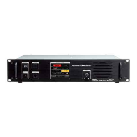
When the Base mode is selected, you can speak into the optional
MH-48A6JA microphone connected to the MIC jack on the front
panel to use this repeater as a transceiver.
Or, you can also control modulated signals input to Pin 6 or Pin 7
using an external PTT.
Once the Base mode is canceled, the repeater returns to the
Repeater mode previously set.
• When the Base mode is set to ON, the repeater reboots
to cancel repeater operations (The screen returns to the
frequency display).
• When the AUTO mode (AMS) is set on the TX side, the Base
mode function does not activate.
• While in Base mode, the communication mode cannot be set.
The communication mode can be set only while in Repeater
mode.
$#5'/1&'
ᲽᲽᲸᲸ
720-+
.
0-+
.
Ჸ
ᲽᲸᲸ
&190
(
/853.
6Z294
.1
$#%-
$#%-
Base mode activation screen
• While in Base mode, the received signal is not repeated.
• Base mode operations are based on the settings configured before entering the Base mode.
• If the repeater enters the Base mode while transmitting/receiving data using the AMS function, PTT operations
will be prohibited.
Pin 2: PTT
When the repeater is operating in the Base mode, and the 5 VDC at this pin is pulled low by an external device, it
keys the repeater transmitter. (Only in Base mode)
Pin 3: CTCSS/DCS
Noise SQL and CTCSS/DCS decoded output. Signaling settings that are set in the SETUP menu will be applied.
(Only in Base mode)
Pin 4: SQL DET
This is an open-collector, active-low output capable of sinking about 10 mA. It indicates that the receiver squelch
is open. If the squelch control is properly set, this indicates a carrier on the receiver channel. (Only in Base mode)
Pin 5: GND
Chassis ground for all logic levels and power supply return.
Pin 6: TONE IN [Transmitter Input] (Sub-audible Band: 5 ~ 250 Hz)
This pin is sub-audible input. Input impedance is 600 Ohms, and has a flat response characteristic (repeater
deviation is constant for a given signal level over the frequency range of 5 ~ 250 Hz). Injecting too high a voltage
here causes over-deviation of CTCSS or DCS, degrading performance.
Use shielded cable to connect to this pin, connecting the shield to GND. (Only in Base mode)
Pin 7: AF IN [Analog Transmitter Input (Packet 1200 bps)] (Voice Band: 300 ~
3,000 Hz)
This pin is audio input. Nominal input level is 1.5 Vp-p. Input
impedance is 600 Ohms. This audio is injected before the splatter
filter stage, so excess signal input levels are clipped.
AF IN is usually used for analog modulation input, however, to
input C4FM digital signals for digital modulation operations,
enter the DR-1 Repeater mode, then touch the up-link frequency
display area to change the packet speed to 9600bps. (Only in
Base mode)
It is impossible to input analog modulation signals and convert
them to digital signals on DR-1.
Use shielded cable to connect to this pin, and connect the shield
to GND.
5'672
᳁ᲿᲸᲸ
720-+
.
0-+
.
Ჸ
ᲽᲸᲸ
&190
(
/853.
$#%-
$#%-
6Z294
.1
+&5'6
+ª%'
/1&'4'/16'
616
&53%1&'
OKP
5+)0#.+0)
53.
41((
61((
2CEMGV5RGGFDRU
Packet speed changing (to 9600bps) screen
Pin 8: DISC OUT [Analog Output] (Wide-Band: 0 ~ 3,000 Hz)
Received signals with standard deviation produce 500 mVp-p audio at this pin. The output impedance is 600
Ohm, and is extracted before the de-emphasis and squelch circuitry. Use shielded cable to connect to this pin, and
connect the shield to GND.
Digital signals can be received as well.
Pin 9: AF OUT [Analog Output]
AF output (300 mVp-p) dedicated for analog mode. De-emphasis is applied.
This pin is an output for AF signal (300 mVp-p), with the signals being extracted after the de-emphasis.
Pins 6, 7, 8, and 9 Functions Controlled by Operation Mode
Pin No Pin Name Receive Mode In Base Mode In Repeater Mode
6 TONE IN Digital Invalid Invalid
Analog Sub-audio modulation
(up to 250 Hz)
Invalid
7 AF IN Digital Digital modulation audio input Invalid
Analog Analog modulation input
(300 Hz ~ 3 kHz)
Invalid
8 DISC OUT Digital Invalid Invalid
Analog Discriminator output Discriminator output
9 AF OUT Digital Demodulated digital audio
output
Demodulated digital audio
output
Analog Analog audio output Analog audio output
Pin 10: GND
Chassis ground for all logic levels and power supply return.
Pins 11 and 12: EXT PORT 1, EXT PORT 2
When [REMOTE] is set to ON in the SETUP menu, the repeater mode is switched according to the EXT PORT1
and EXT PORT2 combinational logic (see the table in the previous page). (Only in Remote mode)
Pin 13: EXT PORT 3
This is an open-collector, active-low output capable of sinking about 10 mA. It indicates that the receiving tone is
invalid. (Only in Remote mode)
Pin 14: EXT PORT 4
This is an open-collector, active-low output capable of sinking about 10 mA. It indicates that the transmitting tone
is invalid. (Only in Remote mode)
Pin 15: VCC [Power Supply]
This pin provides 13.8 V, 2.0 A, DC from the repeater supply. There is an internal 3 A fuse to prevent damage to
the repeater.
MIC jack
By connecting MH-48A6JA to the MIC jack on the front panel while in Repeater mode or Base
mode, voice communications are possible in the mode which is set on the transmitter. However,
when AMS is set on the transmitter, data transmission is not available via the MIC jack on the
front panel.
