Yaesu DR-1X User manual

Before Using
Installation and Connection
Operations
Appendix
144/430MHz 50W
VHF/UHF AMS DIGITAL REPEATER
C4FM FDMA/FM
DR-1X / DR-1XE
Operating Manual

2
Before Using
Introduction
Features of this radio
144/430 MHz repeater is equipped with a standard C4FM digital communication modem capable of selecting the communications
mode automatically
Clear audio and data communication is achieved using the digital modem functions
Transmit power 50 watts with cooling fan
Full color 3.5-inch LCD, high luminance TFT touch panel controller
Intuitive, user touch panel operation
About the touch panel
●Precautions in using the touch panel
The touch panel of the controller is designed to work with the slightest touch of a finger.
The touch panel may not work when a protective film or sheet is affixed to the LCD.
Use of a pointed fingernail or pen to operate the touch panel, or pressing too hard may damage or scratch the screen.
Smart phone operations such as flicking, pinch in and pinch out are not possible.
●Maintaining the touch panel
To clean the touch panel, switch the power supply OFF before using a dry, soft cloth to wipe away dust and dirt from the touch panel.
When the touch panel is really dirty, wet a soft cloth and wring it out thoroughly before using it to wipe the touch panel.
When wiping the touch panel, be careful not to wipe too hard or scratch the surface with your nails.
When the touch panel is scratched, it may become difficult to see the display.
About registered trademarks and copyrights
Company and product names described in this manual are trademarks and registered trademarks of their respective companies.
Unauthorized reproduction or copying of a part or all of the copyrights owned by Yaesu Musen Co., Ltd. in any form whatsoever is
strictly prohibited.
How to read this manual
In this manual, controller operations are expressed as follows:
Touch [SQL] .......................................Indicates that the symbol on the touch panel screen is to be touched quickly.
Select [MODE] ...................................Indicates that the items are to be highlighted on the touch panel screen.
The following symbols are also used in this manual:
Caution
...Explains information to avoid incorrect operation.
Tip
...Explains operating hints and helpful advice.
Also note: the actual product may differ from the drawings shown in this manual.

3
Before Using
Contents
Introduction.................................................................................2
Features of this radio ..............................................................2
About the touch panel.............................................................2
About registered trademarks and copyrights ..........................2
How to read this manual .........................................................2
Before Using .............................................................................4
Safety Precautions (make sure to read these) ...........................4
Accessories ................................................................................6
Options .......................................................................................6
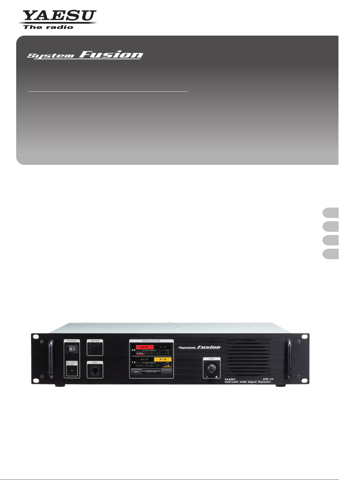
Name and Function of Each Component ...................................7
Front........................................................................................7
Rear ........................................................................................8
Explanation of the screen .......................................................9
Installation and Connection .................................................. 11
Setting up the Repeater............................................................ 11
Safety measures for installation............................................ 11
Installing the repeater ........................................................... 11
Mounting on a desk........................................................... 11
About electrical grounding ....................................................12
About the antenna.................................................................12
Antenna consideration.......................................................12
Connecting the antenna........................................................13
Connecting the Power Supply ..................................................14
Connection for DR-1X...........................................................14
Connection for DR-1XE ........................................................15
Connecting External Devices ...................................................16
Connection of an external microphone or PTT switch ..........16
Connection to a personal computer......................................16
Connection to an external controller .....................................17
To use DR-1X/DR-1XE in Remote mode ..........................18
Repeater Operation ................................................................19
Basic Operations ......................................................................19
Turning the power on ............................................................19
Switching the power off .....................................................19
Setting the ID (call sign)........................................................19
Turning the display on and off...............................................20
Adjusting the volume.............................................................20
Switching the operating mode...............................................21
Switching the communication mode .....................................22
Adjusting the squelch level ...................................................22
Adjusting the transmit power.................................................23
Setting the TX Inhibit.............................................................24
Remote Operation ....................................................................25
Turning remote operation ON/OFF .......................................25
Control from external controller.............................................26
Base Station Operation ............................................................27
Transmitting C4FM digital signals .....................................27
Setting up the Repeater............................................................28
Setup menu basic operations ...............................................28
Setting the frequency............................................................29
Setting the tone signals.........................................................30
Setting the tone frequency ................................................30
Setting the DCS code........................................................30
Switching the tone signal types.............................................31
Setting the digital squelch code ............................................32
Setting the ID (call sign)........................................................32
Setting the ID announcement ...............................................33
Setting the way to announce.............................................33
Setting the announcement output level.............................34
Setting the ID announcement CW speed..........................34
Setting the announcement time interval............................35
Setting the TOT (timeout timer).............................................36
Setting other configuration....................................................36
Setting the repeater for remote operation .........................36
Turning transmission ON/OFF from the remote controller 36
Setting the display turn-on time.........................................37
Setting the Packet Speed..................................................37
Restoring Default Settings (Factory Reset).......................38
Appendix .................................................................................39
Installation of the Optional Voice Guide Unit "FVS-2" ..............39
Maintenance.............................................................................40
Care and maintenance..........................................................40
Replacing the fuse ................................................................40
Advice When There Is a Problem.............................................41
There is no power..............................................................41
There is no sound..............................................................41
There is no transmission ...................................................41
There is no screen on the display .....................................41
About internal spurious signals.............................................41
After-market Services ...........................................................41
Specifications ...........................................................................42

4
Before Using
Safety Precautions (make sure to read these)
Make sure to read this manual in order to use this radio safely and correctly.
Note beforehand that the company shall not be liable for any damages suffered by the customer or third parties in using this product,
or for any failures and faults that occur during the use or misuse of this product, unless otherwise provided for under the law.
Type and meaning of the marks
DANGER This symbol indicates the possibility of death or serious injury being inflicted on the user and the
surrounding people when these instructions are ignored and the product is handled improperly.
WARNING This symbol indicates the possibility of death or serious injury being inflicted on the user and the
surrounding people when these instructions are ignored and the product is handled improperly.
CAUTION
This symbol indicates the possibility of physical impediments occurring or impediments being inflicted
on the user and the surrounding people when these instructions are ignored and the product is handled
improperly.
Type and meaning of symbols
Prohibited actions that must not be carried out in order to use this radio safely.
For example, signifies that disassembly is prohibited.
Precautions that must be adhered to in order to use this radio safely. For example, signifies that the power supply is to
be disconnected.
DANGER
Do not use the device in “locations or aircraft and vehicles
where its use is prohibited” such as in hospitals and
aeroplanes.
This may exert an impact on electronic and medical devices.
Never touch the antenna during transmission.
This may result in injury, electric shock and equipment failure.
Do not transmit in crowded places in consideration of
people who are fitted with medical devices such as heart
pacemakers.
Electromagnetic waves from the device may affect the medical
device, resulting in accidents caused by malfunctions.
Do not operate the device when flammable gas is generated.
Doing so may result in fire and explosion.
Use good engineering, proper grounding and protective
devices to protect the repeater from power surges, lightening
and electrical damage via the power and external antenna
connections.
Otherwise when it thunders, immediately disconnect the
external antenna from the repeater and shut OFF the power
supply.
If not, fire, electric shock and equipment failure this may result.
Do not touch any liquid leaking from the liquid display with
your bare hands.
There is a risk of chemical burns occurring when the liquid comes
into contact with the skin or gets into the eyes. In this case, seek
medical treatment immediately.
WARNING
Do not use voltages other than the specified power supply
voltage.
Doing so may result in fire and electric shock.
Do not transmit continuously for long periods of time.
This may cause the temperature of the main body to rise and
result in burns and failures due to overheating.
Do not dismantle or modify the device.
This may result in injury, electric shock and equipment failure.
Do not handle the power plug and connector etc. with wet
hands. Also do not plug and unplug the power plug with wet
hands.
This may result in injury, electric shock and equipment failure.
When smoke or strange odors are emitted from the radio,
turn off the power and disconnect the power cord from the
socket.
This may result in fire, liquid leak, overheating, damage, ignition
and equipment failure. Please contact our company amateur
customer support or the retail store where you purchased the
device.
Keep the power plug pins and the surrounding areas clean
at all times.
This may result in fire, overheating, breakage, ignition etc.
Do not place the device in areas that may get wet easily (e.g.
near a humidifier).
This may result in fire, electric shock and equipment failure.
When connecting a DC power cord, pay due care not to mix
up the positive and negative polarities.
This may result in fire, electric shock and equipment failure.
Do not use power cords other than the one enclosed or
specified.
This may result in fire, electric shock and equipment failure.
Do not bend, twist, pull, heat and modify the power cord and
connection cables in an unreasonable manner.
This may cut or damage the cables and result in fire, electric
shock and equipment failure.
Do not pull the cable when plugging and unplugging the
power cord and connection cables.
Please hold the plug or connector when unplugging. If not, this
may result in fire, electric shock and equipment failure.
Do not use the device when the power cord and connection
cables are damaged, and when the power connector cannot
be plugged in tightly.
Please contact our company amateur customer support or the
retail store where you purchased the device as this may result in
fire, electric shock and equipment failure.
Before Using

5
Before Using
Safety Precautions (make sure to read these)
Before Using
Do not use fuses other than those specified.
Doing so may result in fire and equipment failure.
Do not allow metallic objects such as wires and water to get
inside the product.
This may result in fire, electric shock and equipment failure.
Disconnect the power cord and connection cables before
incorporating items sold separately or replacing the fuse.
This may result in fire, electric shock and equipment failure.
Follow the instructions given when installing items sold
separately and replacing the fuse.
This may result in fire, electric shock and equipment failure.
Do not use the device when it thunders.
For safety reasons, pull the power plug out of the AC socket.
Never touch the antenna as well. This may result in fire, electric
shock and equipment failure due to thunder.
CAUTION
Do not place this device near a heating instrument or in a
location exposed to direct sunlight.
This may result in deformation and discoloration.
Do not place this device in a location where there is a lot of
dust and humidity.
Doing so may result in fire and equipment failure.
Stay as far away from the antenna as possible during
transmission.
Long-term exposure to electromagnetic radiation may have a
negative effect on the human body.
Do not wipe the case using thinner and benzene etc.
Please use a soft and dry piece of cloth to wipe away the stains
on the case.
Do not put heavy objects on top of the power cord and
connection cables.
This may damage the power cord and connection cables, resulting
in fire and electric shock.
Do not transmit near the television and radio.
This may result in electromagnetic interference.
Do not use optional products other than those specified.
If not, this may result in equipment failure.
Do not place the device on an unsteady or sloping surface, or
in a location where there is a lot of vibration.
The device may fall over or drop, resulting in fire, injury and
equipment failure.
For safety reasons, switch off the power and pull out the
power cord when the device is not going to be used for a
long period of time.
If not, this may result in fire and overheating.
Do not throw or subject the device to strong impact forces.
This may result in equipment failure.
Do not put this device near magnetic cards and video tapes.
The data in the cash card and video tape etc. may be erased.
Keep out of the reach of small children.
If not, this may result in injuries to children.
Do not stand on top of the product, and do not place heavy
objects on top or insert objects inside it.
If not, this may result in equipment failure.
Do not use a microphone other than those specified when
connecting a microphone to the device.
If not, this may result in equipment failure.
Do not touch the heat radiating parts.
When used for a long period of time, the temperature of the heat
radiating parts will get higher, resulting in burns when touched.
Do not open the case of the product except when replacing
the fuse and when installing items sold separately.
This may result in injury, electric shock and equipment failure.

6
Before Using
Accessories
AC Power Cord (T9017882) *1 ............................................................. 1
DC Power Cord with Fuse (T9026115) ................................................ 1
Spare Fuse 15 A (Q0000075) ........................................................... 1
5 A (Q0000143) *1 .......................................................... 1
Case Legs (S4000052) ........................................................................ 4
PC Connection Cable SCU-20 (T9101621) ......................................... 1
Operating Manual (this manual) .......................................................... 1
Warranty Certificate ............................................................................. 1
*1: For DR-1X only
Options
DTMF Microphone MH-48A6JA
Hand Microphone MH-42C6J
Voice Guide Unit FVS-2

7
Before Using
Name and Function of Each Component
Front
X
POWER switch
Press “|” side to switch the radio on, and “O” side to switch the radio off.
Power supply monitor (LED indicator)
• When the indicator illuminates in green, the power is supplied from the AC IN jack (DR-1X only).
• When the indicator illuminates in red, the power supply is backed up through the BACKUP terminals (13.8 V DC).
SETUP button
Press to switch the display on and off.
MIC jack
Insert the plug of the optional microphone to this 6-pin modular jack.
Touch panel display
VOL knob
The audio volume of the received (up link) signal will increase when the knob is turned in a clockwise direction and decrease when
turned in a counter-clockwise direction.
Speaker
The internal speaker is located here.
Handle

8
Before Using
Name and Function of Each Component
Rear
Note The figure above shows the rear panel of the DR-1X.
TX ANT terminal
Connect to the transmitting antenna (down link) with the coaxial cable.
The output impedance requirement is 50 ohms.
Air outlet for cooling fan
RX ANT terminal
Connect to the receiving antenna (up link) with the coaxial cable.
The input impedance requirement is 50 ohms.
FUSE 15A jack
A 15 A fuse for the DC power supply through the BACKUP terminals is attached.
BACKUP terminals
Connect to the 13.8 V DC power supply.
FUSE 5A jack (DR-1X only)
A 5 A fuse for the AC power supply through the AC IN jack is attached.
ACC jack
Connect to a personal computer with the provided PC connection cable “SCU-20”.
CONTROL I/O connector
This connector allows the repeater to be connected to an external controller for remote operation.
AC IN jack (DR-1X only)
Connect to the 100 V to 240 V AC power supply with the provided power cable.
GND terminal

9
Before Using
Name and Function of Each Component
Explanation of the screen
Operation mode screen
TX
RX
RX Receive (up link) band display area
TX Transmit (down link) band display area
Operation mode display area
[AUTO] Touch here to activate the AMS (automatic mode select) function. The communication mode switches automatically
according to the received/transmitted signal types.
[FIX] Touch here to receive/transmit signals in the selected communication mode at all time.
Communication mode display area
The items are displayed in red during the AUTO mode and yellow during the FIX mode.
[NORMAL] Indicates operation is in the simultaneous voice and data communication mode (digital).
[VOICE WIDE] Indicates operation is in the high-rate voice communication mode (digital).
[DATA] Indicates operation is in the high speed data communication mode (digital).
[FM] Indicates operation is in the analog communication mode on the FM band.
RX indicator
This indicator shows green when a signal is received and white when there is no signal.
TX indicator
This indicator shows red when the repeater transmits and white when there is no transmit.
Settings display area
[REMOTE] Displayed in red when remote operation with an external controller is enabled (see page 24).
[SETUP] Touch here to switch the display to the setup mode screen.

10
Before Using
Name and Function of Each Component
Setup mode screen
5'6728GTZZZ':2#
ᲽᲽᲸᲸ
720-+
.
0-+
.
Ჸ
ᲽᲸᲸ
&190
(
/853.
6Z294
.1
$#%-
$#%-
TX
RX
RX Receive (up link) band display area
TX Transmit (down link) band display area
Touch key display area
[BACK] Touch here to return to the operation mode screen.
[SQL] Touch here to set the squelch level of the receiver.
[Tx PWR] Touch here to set the transmitter output level.
[F] Touch here to display the setup menu.
Direction display area
“UP LINK” is displayed on the RX band.
“DOWN LINK” is displayed on the TX band.
Status display area
A green bar is displayed during receive when signals are detected.
The bar will not be displayed when the squelch is turned on.
Frequency display
VOL/SQL level display
S-meter/transmission power level display
Communication mode display
●Squelch level setting screen
The screen appears as below after [SQL] is touched.
5'6728GTZZZ':2#
ᲽᲽᲸᲸ
720-+
.
0-+
.
Ჸ
ᲽᲸᲸ
&190
/853.
$#%-
$#%-
[▲][▼] Thesquelchthresholdwillincreasebytouching[▲]anddecreasebytouching
[▼].

11
Installation and Connection
Setting up the Repeater
Safety measures for installation
Note the followings precautions when installing this repeater.
Use good engineering, proper grounding and protective devices to protect the repeater from power surges, lightening and electrical
damage via the power and external antenna connections.
Do not install the repeater in a place where there is extreme vibration, where there is a lot of dust, excessive humidity or high
temperature, or where it is exposed to direct sunlight.
Install the repeater in a well ventilated position, so heat dissipation is not obstructed. The heat sink becomes hot when transmitting
for long periods of time.
Do not place any objects on top of the repeater.
Note that there is a risk that hum and noise may be introduced, depending on the installation conditions and the external power
source used.
Install the repeater as far as possible away from TV and radio equipment to avoid (TVI, BCI).
In particular, do not install the repeater near indoor antenna elements.
Installing the repeater
Place the repeater on a flat and level rack or shelf, with its bottom side down.
We recommend securing the wings of the repeater front panel to the equipment rack or shelf with bolts.
Mounting on a desk
When using the repeater in a desktop location instead of a rack or shelf, attach the four supplied legs onto the bottom of the repeater
case.

12
Installation and Connection
Setting up the Repeater
About electrical grounding
The DR-1X/DR-1XE repeater, like any other communications apparatus, requires an effective ground system for maximum electrical
safety and best communications effectiveness. A good ground system can contribute to station efficiency in a number of ways:
• It can minimize the possibility of electrical shock to the operator.
•It can minimize RF currents flowing on the shield of the coaxial cable and the chassis of the repeater. Such currents may lead to
radiation, which can cause interference to home entertainment devices or laboratory test equipment.
• It can minimize the possibility of erratic repeater/accessory operation caused by RF feedback and/or improper current flow through
logic devices.
To prevent damage from lightning,
atmospheric electricity, electrical shock,
etc., provide a good earth ground.
Use a short, thick, braided
cable to connect your
station equipment to
the buried ground rod
(or alternative earth
ground system).
Note The figure above shows the rear panel of the DR-1X.
About the antenna
A good antenna installation is extremely important for transmission and reception purposes. Note the followings, as the type and
characteristics of the antenna largely determines whether the performance of the repeater can be fully realized.
• Use an antenna that is designed for the installation conditions and application objective.
• Use an antenna that is tuned for the operating band and frequency.
• Useanantennaandaco-axialcablewithacharacteristicimpedanceof50Ω.
• AdjusttheVSWR(standingwaveratio)untilitis1.5orlessforanantennawithanadjustedimpedanceof50Ω.
• Keep the coaxial cable routing length as short as possible.
• Use lightening and voltage surge protection devises.
Antenna consideration
Repeater operation without a duplexer requires that two antennas be installed, one for receiving and one for transmitting, so that the
receiving antenna does not absorb energy from the transmitting antenna. There are a number of ways to do this, depending on the
TX/RX frequency separation, and on the locations available for antenna mounting. If a duplexer is used, a single antenna suffices for
both transmitting and receiving. If using a reduced-size duplexer, a six-cavity model (minimum) is recommended. Yaesu recommends
the use of the duplexer. For further details, contact your Yaesu dealer.
Regardless of the above choice, it is of paramount importance that the antenna(s) be mounted as high and in the clear as possible,
preferably within line-of-sight to all repeater users. Furthermore, losses in the feedline(s) must be minimized, so the feedline(s) should
be high quality, and as short as possible. If a long feedline is necessary, use coaxial “hardline” cable to reduce losses. Repeater
antennasshouldhaveanimpedanceof50Ωattheoperatingfrequency.Whenseparatereceiveandtransmitantennasareused,
high-Q narrow-band types may serve to minimize interaction. However, when a single antenna is used with a duplexer, it should be a
low-Q wide-band type.
Cautions
zNever transmit without having a transmit antenna connected to the TX antenna jack of the Repeater.
zCreate a loop (slack) in the coaxial cable directly underneath the antenna and fasten it so that the weight of the cable does not pull on the antenna or
connector itself.
zInstall the antenna taking into consideration the securing supports and how the guying wires are positioned, so that the antenna does not fall over or get
blown away in strong winds.

13
Installation and Connection
Setting up the Repeater
Connecting the antenna
1Plug the coaxial connectors into the TX ANT and RX ANT jacks respectively at the rear of the repeater, and tighten the shields onto
the jacks.
Note The figure above shows the rear panel of the DR-1X.
2To use a duplexer prepared by yourself, plug in the terminal of the coaxial cables from the TX ANT and RX ANT terminals into the
jacks of the duplexer, and turn to tighten
3Plug in the terminal of the coaxial cable connected to the antenna into the jack of the duplexer, and turn to tighten
From RX ANT
Duplexer
To antenna
From TX ANT

14
Installation and Connection
Connecting the Power Supply
Connection for DR-1X
●Main power
Caution
zUse an AC outlet capable of supplying AC 100 to 240 V at 50 or 60 Hz.
1Insert the socket of the provided AC power cord into the AC IN jack at the rear of the repeater
2Insert the plug of the provided AC power cord into the AC outlet
●Backup power
For uninterrupted operation during power failures, a 13.8 V rechargeable automotive type battery (55-Ah or more recommended) may
be connected to the BACKUP terminal posts on the rear panel. In the event of an AC power outage, the automatic power control circuit
will automatically switch the repeater to the backup battery, and operation will not be interrupted.
If the power is out for a long time, the battery may be completely discharged. When the power is restored the DC startup current may
blow the protection fuse. So the protection fuse in charge circuit should be checked after an outage.
While operating from a battery or DC supply, the repeater requires approximately 14 A at 13.8 V during transmit.
Follow the outline in the illustration regarding the proper connection of the DC power cable.
Always observe proper polarity when making DC connection.
Cautions
zUse a power source capable of supplying DC 13.8 V and a current capacity of 14 A or more.
zMake sure to switch OFF the power of the external power source before connecting.
1Insert the socket of the provided DC power cord to the BACKUP jack at the rear of the repeater
2Connect the red wire (+) of the provided DC power cord to the positive (+) terminal of the external power source, and the black
wire (-) to the negative (-) terminal
+
(red)
Fuse (15 A)
–
(black)

15
Installation and Connection
Connecting the Power Supply
Connection for DR-1XE
Follow the outline in the illustration regarding the proper connection of the DC power cable.
The DC power connector for the DR-1XE must only be connected to a DC source providing 13.8 V DC (±15 %), and capable of at
least 10 A of current.
Always observe proper polarity when making DC connection.
Caution
zMake sure to switch OFF the power of the external power source before connecting.
1Insert the socket of the provided DC power cord to the DC IN jack at the rear of the repeater
2Connect the red wire (+) of the provided DC power cord to the positive (+) terminal of the external power source, and the black
wire (-) to the negative (-) terminal
+
(red)
Fuse (15 A)
–
(black)
Tip
The external power source should be installed near the equipment and should be easily accessible.
Permanent damage can result when improper supply voltage, or reverse-polarity voltage, is applied to the DR-1XE. The
Limited Warranty on this radio does not cover damage caused by application of AC voltage, reverse polarity DC, or DC
voltage outside the specified range of 13.8 V ±15 %. When replacing fuses, be certain to use a fuse of the proper rating.
The DR-1XE requires a 15 A blade fuse.

16
Installation and Connection
Connecting External Devices
Connection of an external microphone or PTT switch
ByconnectinganoptionalmicrophoneMH-48A6JAtothe[MIC]jackonthefrontpanel,voicecommunicationsarepossibleinthe
modewhichissetonthetransmitter.Except,whenAMSissetonthetransmitter,datatransmissionisnotavailableviathe[MIC]jack.
Connection to a personal computer
The provided PC connection cable “SCU-20” and other optional cables can be used to connect the repeater to a personal computer
as a COM port.
Usethe[ACC]jackatthebackoftherepeatertoconnectwiththepersonalcomputer.
Thepinassignmentsofthe[ACC]jackareasfollows.
PKD (packet data input)
GND
PSK (PTT)
RX 9600 (9600 bps packet data output)
RX 1200 (1200 bps packet data output)
PK SQL (squelch control)
TXD(serialdataoutput[transceiver→PC])
RXD(serialdataoutput[transceiver←PC])
CTS (data communication control)
RTS (data communication control)
Tips
• Make sure to switch off the power to the radio before connecting the cable.
• When using the PC connection cable “SCU-20”, a dedicated driver needs to be installed in the personal computer. Download and use the driver and
installation manual from the YAESU website.

17
Installation and Connection
Connecting External Devices
Connection to an external controller
To control the DR-1X/DR-1XE remotely, optional cables can be used to connect the repeater to an external controller.
Usethe[CONTROLI/O]connectoratthebackoftherepeatertoconnectwiththeexternalcontroller.
To interface the DR-1X/DR-1XE with an external controller, additional cables with a 15-pin mini d-sub connector are needed to connect
tothe[CONTROLI/O]connector.Yourcontrollermayalsorequirerewiring.
Link operation may require four connections: receiver audio, transmitter audio, receiver COR, and transmitter PTT; however these are
notavailableonthe[CONTROLI/O]connector.
Thepinassignmentofthe[CONTROLI/O]connectorisasfollows.
5~1
10~6
15~11
Pin No Pin Name I/O Descriptions
1 EXT I/O Input [L]GND:Remotemode[H]OPEN:Repeatermode
2 PTT Input [L]GND:EXTPTTON[H]OPEN:EXTPTTOFF
When this pin is pulled low by an external device, it keys the repeater transmitter.
Tip On signaling while controlling the external PTT:
Pin 6 (TONE IN) ... Valid
Pin 7 (AF IN) ... Invalid
3 CTCSS/DCS
(PKSQL)
Output [L]GND:Decoded[H]OPEN:Un-decoded
Signaling settings in the repeater setup menu will be applied.
4 SQL DET
(Noise SQL)
Output [L]GND:SQLopen[H]OPEN:SQLclose
This is an open-collector, active-low output capable of sinking about 10 mA. It indicates
that the receiver squelch is open. If the squelch control is properly set, this indicates a
carrier on the receiver channel.
5 GND GND Chassis ground for all logic levels and power supply return
6 TONE IN Input CTCSS/DCS EXT input / 600 ohm, 500 mV peak to peak
Valid during external PTT control
This pin is sub-audible tone input, and has a flat response characteristic (repeater
deviation is constant for a given signal level over the frequency range of 5 ~ 250
Hz). Injecting a too high signal level here causes over-deviation of CTCSS or DCS,
degrading performance.
Use shielded cable to connect to this pin, connecting the shield to GND.
7 AF IN Input EXT Modulation input / 600 ohm, 1.5 V peak to peak
Valid during external PTT control
This pin is audio input (300 ~ 3,000 Hz). This audio is injected before the splatter filter
stage, so excess signal input levels are clipped.
It is impossible to input analog modulation signals and convert them to digital signals
on DR-1X/DR-1XE.
Use shielded cable to connect to this pin, and connect the shield to GND.
Tip AF IN is usually used for analog modulation input with a packet speed of 1200 bps, however,
to input C4FM digital signals for digital modulation operations, enter the DR-1X/DR-1XE
Repeater mode, then touch the up-link frequency display area to change the packet speed to
9600 bps.
8 DISC OUT Output Up-link RX DISC output (w/o de-emphasis), 500 mV peak to peak
Discriminator output during up-link reception. Does not affect the operation mode of the
repeater.
Received signals with standard deviation produce 500 mVp-p audio (0 ~ 3,000 Hz) are
output at this pin. The signal is extracted before the de-emphasis and squelch circuitry.
Use shielded cable to connect to this pin, and connect the shield to GND.
9 AF OUT Output Up-link RX AF output (w/ de-emphasis), 300 mV peak to peak
Analog audio output during up-link reception. Does not affect the operation mode of the
repeater.
This pin is an output for AF signal (300 mVp-p), being extracted after the de-emphasis.
Demodulated digital signals can be output as well.
10 GND GND Chassis ground for all logic levels and power supply return

18
Installation and Connection
Connecting External Devices
Pin No Pin Name I/O Descriptions
11 EXT port 1*1Input In Remote mode, the logic combination of Ports 1 and 2 determines the transmit and
receive modes as below:
Port 2 Port 1 RX TX
H H Auto
(AMS)
FM
H L FM FM
L H Digital Digital
L L Auto
(AMS)
Auto
(AMS)
12 EXT port 2*1Input
13 EXT port 3*1Input [L]GND:RXToneOFF[H]OPEN:Setupmode
Input a low level signal to indicate that the receiving tone is invalid.
14 EXT port 4*1Input [L]GND:TXToneOFF[H]OPEN:Setupmode
Input a low level signal to indicate that the transmitting tone is invalid.
15 VCC VCC Power supply
This pin provides 13.8 V, 2.0 A, DC from the repeater supply. There is an internal 3 A
fuse to prevent damage to the repeater.
*1: These functions may only be activated while the repeater is in Remote mode.
Pins 6, 7, 8, and 9 Functions Controlled by Operation Mode
Pin No Pin Name Receive Mode In Repeater / Remote Mode
6 TONE IN Digital Invalid
Analog Invalid
7 AF IN Digital Invalid
Analog Invalid
8 DISC OUT Digital Invalid
Analog Discriminator output
9 AF OUT Digital Demodulated digital audio
output
Analog Analog audio output
Caution
Even when using the DR-1X/DR-1XE with an external controller, the COR, analog and digital IDs, TOT, DSC/CTCSS, TX power, etc.
are already controlled by the DR-1X/DR-1XE internal control. These internal controls cannot be disabled. The external controller
must not conflict with these functions. Some functions of the internal controller cannot be overridden.
Before connecting an external controller you must make sure which functions are already internally controlled. Special precautions
must be considered when planning to link with external systems.
Tips
• Make sure to switch off the power to the radio before connecting the cable.
• In case of jamming or interfering signal while in Repeater mode, Pin 1 may be grounded by external control to temporarily disable repeating the receiver
input.
To use DR-1X/DR-1XE in Remote mode
By setting [REMOTE]inthesetupmenutoONandinputtingalowleveltoPin1ofthe[CONTROLI/O]connector,therepeatermaybe
used in Remote mode and controlled remotely by the external controller. Pins 1, 8, 9, 11, 12, 13 and 14 may be used for input, output
and control while in Remote mode.
For details, see “Remote Operation” (Page 25).

19
Repeater Operation
Basic Operations
Turning the power on
1Press the “|” side of the POWER switch
The power will be switched on, and the power supply monitor (LED indicator) will
illuminate.
Tips • When the power is supplied from the AC IN jack, the indicator illuminates in green (DR-1X
only).
• When the power is supplied through the BACKUP terminals (13.8 V DC), the indicator
illuminates in red.
The operation mode screen will appear on the display.
Switching the power off
1Press the “O” side of the POWER switch
The power supply monitor and the display will turn off, and the power will be switched off.
Setting the ID (call sign)
When switching the power on for the first time after purchasing, or after resetting the radio, you must enter the call sign.
1Touch [F] in the setup mode screen
The setup menu will appear.
2Touch [ID SET]
The character input screen will appear.
5'6728GTZZZ':2#
᳁ᲿᲸᲸ
720-+
.
0-+
.
Ჸ
ᲽᲸᲸ
&190
(
/853.
6Z294
*+
$#%-
$#%-
+&5'6
+&# 00170%'
/1&'4'/16'
616
&53%1&'
OKP
5+)0#.+0)
53.
41((
61((
3Touch a character key
The touched character will be displayed at the top of the screen.
Tips • Each time [ ] is touched the cursor will move to the left and erase one character.
• The input screen changes between numbers input and alphabet input each time [ABC] is
touched.
• The cursor in the input field moves left or right when [←] or [→] are touched.
• Alphabets, numbers, and a hyphen up to 10 characters can be entered.
39'46; 7 +12
#5&()*,- .
<:%8$0/
#$%5RCEG
@
ᲹᲺ
%CRU
$#%-
+&5'6
4Touch [ENT]
The ID setting is saved and the display will return to the setup menu.
Tip When switching the power ON for the first time after purchasing, or after resetting the radio, a
screen will be displayed requesting the repeater ID be entered.
39'46; 7 +12
#5&()*,- .
<:%8$0/
#$%5RCEG
'06
@
ᲹᲺ
%CRU
+&5'6
2%ᲹᲹ Ჺ
;
*,
Repeater Operation

20
Repeater Operation
Basic Operations
Turning the display on and off
1Press the SETUP button for 1 second to turn the display off
2Press the SETUP button for 3 seconds to turn the display on
Tip
The display can be set to turn off automatically after a period of time with no operation. See “Setting the display turn-on time” (Page 37) for details.
Adjusting the volume
1Turn the VOL knob
The monitor speaker audio volume of the received (up link) signal will increase when
the knob is turned in a clockwise direction and decrease when the knob is turned in a
counter-clockwise direction.
Other manuals for DR-1X
4
This manual suits for next models
1
Table of contents
Other Yaesu Repeater manuals

Yaesu
Yaesu Wires-X User manual

Yaesu
Yaesu VXR-9000 User manual

Yaesu
Yaesu DR-2X User manual

Yaesu
Yaesu DR2XLAN User manual

Yaesu
Yaesu WIRES-X HRI-200 User manual

Yaesu
Yaesu VXR-7000U User manual

Yaesu
Yaesu DR-1X User manual

Yaesu
Yaesu DR-1X User manual

Yaesu
Yaesu DR-2X Manual

Yaesu
Yaesu WIRES-X TM-400FT5D Installation and operation manual