Yaesu DR-1X User manual

DR-1X/XE
Installation Instructions for the DR-1X/XE
RX-UNIT (V1.00t) and DSP rmware (V4.11)
Attention !
Two versions of the update firmware are available. Before in-
stalling the new rmware, please check the rmware version of
the DR-1X/XE referring to Page 2.
rV1.00m replaces V1.00b and any versions other than
V1.00f which is for Wide-FM operation
rV1.00t replaces V1.00f for Selectable Wide/Narrow-FM
operation
This rmware update contains the following additional features.
If you are not interested in these features, you may skip this
rmware update.
m Adjustable Squelch Hysteresis
m Adjustable Squelch Tail
m CWID/Voice announcements with stripped PL Tones
* If the DR-1X/XE Repeater has the rmware V.1.10D, all these
features and other updates have been already installed, and
you do not need to install this rmware.
YAESU MUSEN CO., LTD.

2
Introduction
This rmware update contains the following additional features. If you are not interested in these features,
you may skip this rmware update.
• Adjustable Squelch Hysteresis
• Adjustable Squelch Tail
• CWID/Voice Announcements with stripped PL Tones
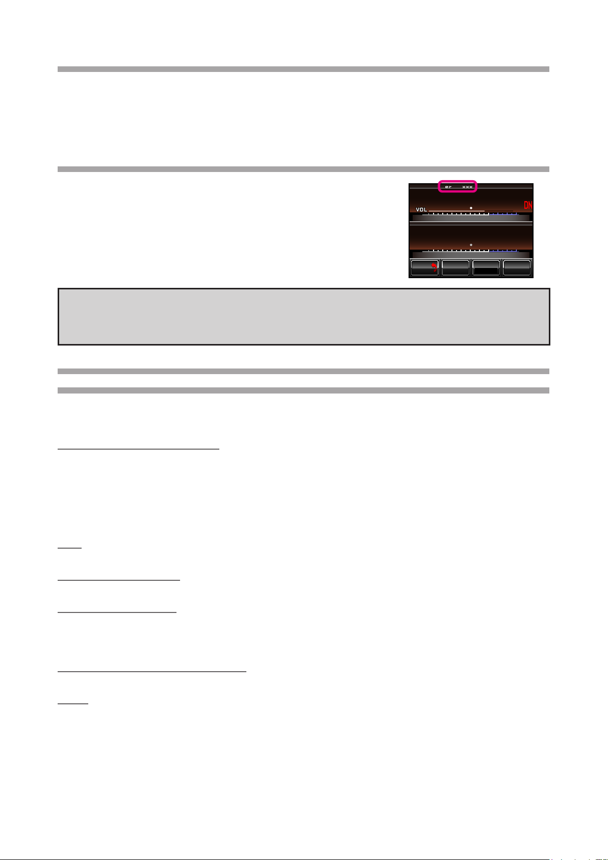
How to check the rmware version of the DR-1X Repeater
1. Turn the DR-1X/XE power ON.
2. Touch [SETUP] on the DR-1X/XE LCD screen.
The rmware version will be displayed at the top of the screen.
3. After conrming the rmware version, turn the DR-1X/XE power OFF.
SETUP Ver.1.xxx EXP A1
UPNKI
L
NKI
L
DOW N
F
M/VSQL
Tx PW R
HI
BACK
BACK
CAUTION!
Be sure to conrm the model and the version of your repeater before starting the installation.
Writing incorrect rmware to the repeater may cause abnormal operation or failure.
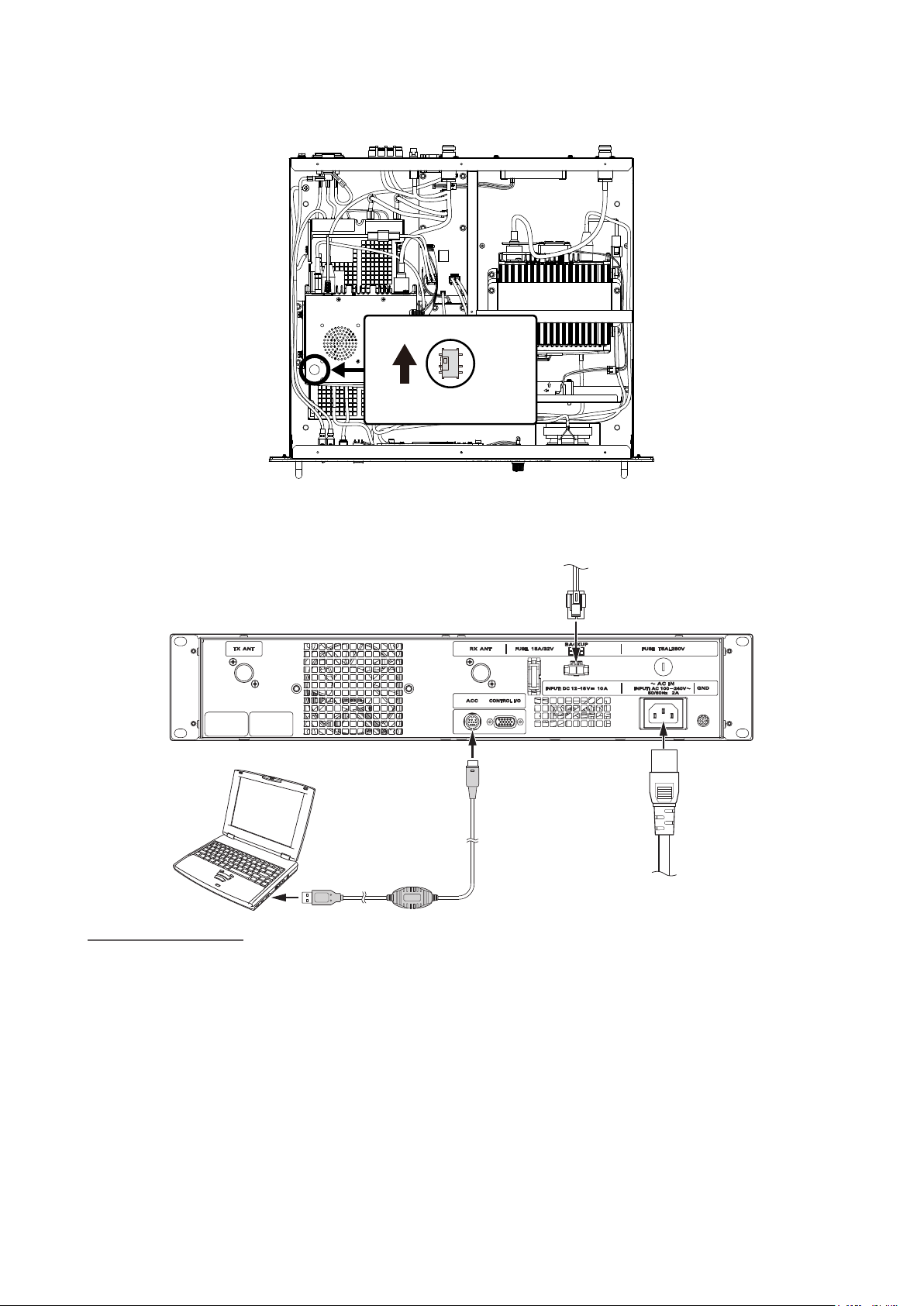
Necessary material and System Requirements (Operating Environment)
for Firmware installation
Notes: In order to use this program, a personal computer (PC) with one of the following Windows operating
systems and a SCU-20 PC connection cable are required.
Supported Operating Systems
The rmware installation programmer requires one of the following operating system environments:
• Microsoft® Windows® 10 (32 bit / 64 bit)
• Microsoft® Windows® 8.1 (32 bit / 64 bit)
• Microsoft® Windows® 8 (32 bit / 64 bit)
• Microsoft® Windows® 7 (Service Pack 1 or later)
• Microsoft® Windows VistaTM (Service Pack 2 or later)
CPU
The CPU performance must satisfy the operating system requirements.
RAM (System Memory)
The RAM (system memory) must be more than sufcient to satisfy the operating system requirements.
HDD (Hard Disk Drive)
The HDD capacity must exceed the operating system requirements.
In addition to the required operating system memory space, about 50 MB of additional memory space is re-
quired to run the rmware installation program.
Necessary PC peripheral interfaces
An available USB interface (USB Port)
Cable
SCU-20 PC connection cable

3
Important Notes
• All responsibility for the use of this software lies with the customer. YAESU MUSEN CO., LTD cannot be
held liable in any way for damages or losses, which may be incurred by the customer as a result of using
this software.
• Copyrights and all other intellectual property rights for the software, as well as the software manual, are the
property of YAESU MUSEN CO., LTD.
• Revision, modication, reverse engineering, or decompiling of this software is prohibited. Redistribution,
transfer, or resale of downloaded les, is also prohibited.
• Downloaded les are for personal use only, any commercial use is prohibited.
• If you cannot perform the rmware installation yourself, please consult with one of our sales sites or service
centers for assistance.
Company and product names described in this manual are trademarks or registered trademarks.
Microsoft®, Windows®, Windows Vista®, Windows® 7, Windows® 8, Windows® 8.1, Windows®10 are
registered trademarks of Microsoft Corporation in the United States and other countries.
Install / Uninstall Procedure
Installation procedure
Please visit Yaesu website (http://www.yaesu.com/) and download the Firmware les (see below).
• RX-UNIT: DR-1X_MAIN_vR100t
• DSP: PCTOOLe_v0411
Uninstall procedure
Delete the folder opened by the program.
The operation will end if the opened folder is deleted since no data will be written to the registry and system
folder.

4
Using the Programmer
Before attempting to update the rmware, use the SCU-20 PC Connection Cable and install the
driver software.
Then go to the website (http://www.yaesu.com/) to download and install the SCU-20 driver.
When the programmer is opened on the computer, press the [Update] button to display the preparation
procedure screen, which explains the rmware installation process. Follow the procedure below.
Installation of the RX-UNIT rmware
1. Remove the 15 screws from the top cover and then remove the cover.
RX-Unit

5
2. Through the hole at the front left of the RX-UNIT case, change the RX-UNIT rmware-writing switch in-
side to the BOOT position (rearward).
Firmware writing switch
BOOT
3. Connect the SCU-20 PC connection cable to the ACC jack, and connect the AC or DC power cord to DR-
1X (DC power cord to DR-1XE).
SCU-20
AC 100 V - 240 V
(USA, EXP, AUS, CHN)
DC 12 V - 15 V (EU)
Install the rmware
1. Turn the DR-1X/XE power ON.
The cooling fan will start rotating but nothing will appear on the LCD screen.
2. Open the “DR-1X_MAIN_vR100t” folder on the personal computer, and then Double-click the “DR-1X_
MAIN_vR100t(exp).exe” le that is saved on your PC to execute the program.
3. Follow the on-screen instructions on your PC to install the DR-1X/XE rmware.
4. Select the COM Port number assigned when you installed the SCU-20, and press “Update”.
5. After the installation completes, turn the DR-1X/XE power OFF, and then trough the hole at the forward
left of the RX-UNIT case, set the RX-UNIT rmware writing switch inside to the original position (forward).
6. Turn ON the DR-1X/XE, power and then touch [SETUP] to view the rmware version number displayed
at the top of the screen. If the install was successful, the rmware version number (Ver. 1.00t) will be dis-
played.

6
Installation of the DSP rmware
Note: Install the MAIN rmware before attempting to Install the DSP rmware.
1. Connect the SCU-20 PC connection cable to the ACC jack on the DR-1X rear panel.
SCU-20
AC 100 V - 240 V
(USA, EXP, AUS, CHN)
DC 12 V - 15 V (EU)
2. Touch and hold the DR-1X/XE LCD screen while turning the DR-1X/XE ON.
3. Press the [SETUP] switch button, (although “PUSH DISP” message is displayed on the screen).
"DSP <--> COM" will appear on the display
Install the rmware
1. Open the “PCTOOLe_v0411” folder on the personal computer, and then Double-click the “PCTOOLe_
v0411.exe” le that is saved on your PC to execute the rmware installation program.
2. Select the COM Port number that was assigned when you installed the SCU-20 programming cable, and
then press “OK”.
3. When the pop-up screen is displayed, press the “OK” button
4. After the rmware installation completes, press “OK”.
5. Turn the DR-1X/XE power OFF.
6. Disconnect the SCU-20 programming cable.
7. Replace the top cover, and fasten it using the 15 screws.
This completes the rmware installation process.

7
The following functions have been added to the DR-1X/XE repeater.
SQL HYSTERESIS
Hysteresis is the difference between the signal level that will open the receiver squelch, and the signal level
at which the squelch again closes. Increasing the hysteresis will suppress repeated opening and closing of
the squelch.
1. Touch [SETUP] in the operation mode screen
The setup mode screen will appear.
REMOTE
2. Touch [F] in the setup mode screen
The setup menu will appear.
SETUP Ver.1.xxx EXP A1
UPNKI
L
NKI
L
DOW N
F
M/VSQL
Tx PW R
HI
BACK
BACK
3. Touch [TOT]
The menu list will appear.
SETUP Ver.1.xxx EXP A1
UPNKI
L
NKI
L
DOW N
F
M/VSQL
Tx PW R
HI
BACK
BACK
ID SET
ID AN NO U NC E
MODE/REMOTE
003
TOT
DSQ CODE
3min
SQL
R-OFF
T-OFF
4. Select and touch [SQL SETTING]
SETUP Ver.1.xxx EXP A1
UPNKI
L
NKI
L
DOW N
F
M/VSQL
Tx PW R
LO
BACK
BACK
TOT 3 min
SQL SETTING >
5. Select and touch [SQL HYSTERESIS]
6. Touch [▲]or [▼]
The set value will change in the following sequence each time it is
touched.
“NORMAL” à “HIGH” à “MAX”
NORMAL: The squelch open signal level and the squelch close signal
level are the same.
HIGH: The squelch open signal level is higher than the squelch
close signal level. (Makes squelch less likely to close.)
MAX: The squelch open signal level is much higher than the
squelch close level. (Makes squelch even less likely to
close.)
Tip Factory default: NORMAL
SETUP Ver.1.xxx EXP A1
UPNKI
L
NKI
L
DOW N
F
M/VSQL
Tx PW R
LO
BACK
BACK
SQL HYSTERESIS NORMAL
SQL TAIL TIME 2500ms
7. Touch [BACK]
The setting is determined and the display will return to the setup menu.

8
SQL TAIL TIME
Enables setting the time duration of the downlink transmit after the uplink signal ceases.
1. Touch [SETUP] in the operation mode screen
The setup mode screen will appear.
REMOTE
2. Touch [F] in the setup mode screen
The setup menu will appear.
SETUP Ver.1.xxx EXP A1
UPNKI
L
NKI
L
DOW N
F
M/VSQL
Tx PW R
HI
BACK
BACK
3. Touch [TOT]
The menu list will appear.
SETUP Ver.1.xxx EXP A1
UPNKI
L
NKI
L
DOW N
F
M/VSQL
Tx PW R
HI
BACK
BACK
ID SET
ID AN NO U NC E
MODE/REMOTE
003
TOT
DSQ CODE
3min
SQL
R-OFF
T-OFF
4. Select and touch [SQL SETTING]
SETUP Ver.1.xxx EXP A1
UPNKI
L
NKI
L
DOW N
F
M/VSQL
Tx PW R
LO
BACK
BACK
TOT 3 min
SQL SETTING >
5. Select and touch [SQL TAIL TIME]
6. Touch [▲]or [▼]
The set value will change in the following sequence each time it is
touched.
0ms
à 50ms à100ms à 150ms à200ms à 250ms à300ms à
à 350ms à 400ms à 450ms à 500ms à 600ms à700ms à
à800ms à900ms à1s à1.1s à1.2s à1.3s à 1.4s à 1.5s à
à 1.6s à1.7s à1.8s à1.9s à2.0s à2.1s à2.2s à2.3s à
à 2.4s à 2.5s
Tip Factory default: 0ms
SETUP Ver.1.xxx EXP A1
UPNKI
L
NKI
L
DOW N
F
M/VSQL
Tx PW R
LO
BACK
BACK
SQL HYSTERESIS NORMAL
SQL TAIL TIME 2500ms
Note This setting is effective only when the uplink call termination signal cannot be received normally.
7. Touch [BACK]
The setting is determined and the display will return to the setup menu.

9
New set item added to [ID ANNOUNCE]
In the Setup menu, touch [ID ANNOUNCE] and then touch [ANNOUNCE].
“CW wo TONE” and “VC wo TONE” have been newly added to the ANNOUNCE mode.
When “CW wo TONE” is selected, The CTCSS TONE or DCS code (or other code) will not be added to the
signal while the INTERVAL CW ID is transmitted.
When “VC wo TONE” is selected, The CTCSS TONE or DCS code (or other code) will not be added to the
signal while the voice ID announcement is being transmitted.
Note Please note the following regarding operation of the repeater ID when the ANNOUNCE mode is set
to “CW wo TONE” or “VC wo TONE”.
1. During initial activity after the DR-1X/XE is first powered on; the ID is sent with tone when the
ANNOUNCE mode is set to “CW wo TONE” or “VC wo TONE”.
2. During repeater inactivity the ID will be sent without tone when “CW wo TONE” or “VC wo TONE” is
selected.
3. If the DR-1X/XE is sending the ID and a user transmits, the incoming audio is muted until the ID is
nished being sent when “CW wo TONE” or “VC wo TONE” is selected.
4. When the DR-1X/XE is active and the ID timer expires, the ID is sent with tone when “CW wo TONE” is
selected. The ID and ongoing audio are mixed.
5. When the DR-1X/XE is active and the ID timer expires, the ID is sent with tone when “VC wo TONE” is
selected. The Voice ID and ongoing audio are not mixed, the ongoing audio is muted while the Voice ID
is sent.

1601-A0
Copyright 2016
YAESU MUSEN CO., LTD.
All rights reserved.
No portion of this manual
may be reproduced
without the permission of
YAESU MUSEN CO., LTD.
Other manuals for DR-1X
4
This manual suits for next models
1
Table of contents
Other Yaesu Repeater manuals

Yaesu
Yaesu Wires-X User manual

Yaesu
Yaesu DR-2X User manual

Yaesu
Yaesu WIRES-X HRI-200 User manual

Yaesu
Yaesu WIRES-X TM-400FT5D Installation and operation manual

Yaesu
Yaesu DR-1 User manual

Yaesu
Yaesu FTR-710A User manual

Yaesu
Yaesu WIRES-X HRI-200 User manual

Yaesu
Yaesu DR-1X User manual

Yaesu
Yaesu WIRES-X FT3D User manual

Yaesu
Yaesu DR-2X Manual