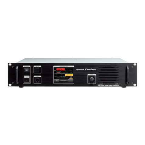
Yaesu DR-1X FR User manual

VHF/UHF C4FM/FM
50W AMS DIGITAL REPEATER
Operating Manual
DR-1X FR
DR-1XE FR

About this manual ................................................. 2
Introduction............................................................ 1
Features of this repeater ..................................... 1
About the touch panel ......................................... 1
Safety Precautions (make sure to read these).... 1
Setting up the Repeater ........................................ 3
Safety measures for installation .......................... 3
Installing the repeater.......................................... 3
About electrical grounding................................... 3
Connecting Antenna Cables................................ 4
Connecting the Power Supply ............................. 5
Connecting External Devices .............................. 6
Accessories and Options ..................................... 7
Supplied Accessories .......................................... 7
Optional Accessories........................................... 7
Name and Function of Each Component ............ 7
Front Panel.......................................................... 7
Rear Panel .......................................................... 8
1. Initial set up........................................................ 9
Turn the power on ............................................... 9
Set up the ID (call sign) ....................................... 9
2. Set up Operation Mode ................................... 10
3. Set up Frequency ............................................ 11
4. Set up Other Functions................................... 12
Adjusting the squelch level................................ 12
Adjusting the transmit power ............................. 12
Adjusting the volume ......................................... 12
Turning the display ON and OFF....................... 12
5. Base mode operation...................................... 13
6. Set up DG-ID Number...................................... 14
Digital Group Identication (DG-ID)................... 14
Setting the DG-ID Number ................................ 14
7. Set up DP-ID..................................................... 16
Digital Personal Identication (DP-ID)............... 16
Registering the DP-ID ....................................... 16
Delete the registered DP-ID .............................. 17
8. Remote Controls.............................................. 18
Setting the remote control ................................. 18
C4FM DIGITAL CONTROL................................ 19
ECS (for analog FM mode) ............................... 19
Change the remote command........................... 20
9. Actual remote control procedure................... 22
Remote Control for C4FM Digital ...................... 22
Remote Control for Analog FM.......................... 23
10. Set Up Various Functions ............................. 24
Setting the tone signals for analog FM mode.... 25
Setting the TOT (time out timer) ........................ 25
Setting the SQL HYSTERESIS ......................... 25
Setting the SQL TAIL LENGTH ......................... 26
Set the ID announcement for analog FM mode
... 26
Set the tone signal type for analog FM mode.... 27
Setting the display turn-off time......................... 27
Password........................................................... 27
Setting the half deviation operation ................... 28
11.
Restoring Default Settings (Factory Reset)
... 29
12. Connect to the HRI-200 node station........... 30
13.
Remote Operation with External Controller
... 33
Turning remote operation ON/OFF.................... 33
Control from external controller ......................... 33
Setting to connect the
repeater controller S-COM7330 ........................ 36
Connection with S-COM7330 and DR-1X ......... 36
Connecting S-COM7330 ................................... 37
14. Installation of the Optional Accessories ..... 38
Installing the optional Voice Guide Unit FVS-2
... 38
15. Specications ................................................ 39
16. After-market Services ................................... 39
YAESU LIMITED WARRANTY.......................... 40
About this manual
This manual contains symbols and conventions to call attention to important information.
Symbols Description
This icon indicates cautions and alerts the user should be aware of.
This icon indicates helpful notes, tips and information.
About registered trademarks and copyrights
Company and product names described in this manual are trademarks and registered trademarks of their
respective companies.
Unauthorized reproduction or copying of a part or all of the copyrights owned by Yaesu Musen Co., Ltd. in any
form whatsoever is strictly prohibited.
Contents

1
Introduction
Features of this repeater
Congratulations on your purchase of the DR-1X Yaesu 144/430MHz Dual Band Dual Receive C4FM/FM Digital
Repeater.
The YAESU DR-1X is a C4FM digital / analog FM dual mode repeater that covers the VHF and UHF amateur
radio bands. DR-1X incorporates the use of Analog FM communication integrated with the C4FM digital
communication through its unique AMS capability.
r The Dual-band repeater is equipped with the VHF and the UHF Amateur radio bands.
rThe AMS feature is able to relay both the C4FM and the Analog FM signals.
rThe C4FM digital modes may be transferred the GPS information.
r Within the DG-ID feature, only the group members may communicate via the repeater.
r Within the Digital Personal ID (DP-ID) feature, the system manager may control some repeater settings
remotely.
About the touch panel
Precautions in using the touch panel
The touch panel of the controller is designed to work with the slightest touch of a finger.
The touch panel may not work when a protective film or sheet is affixed to the LCD.
Use of a pointed fingernail or pen to operate the touch panel, or pressing too hard may damage or scratch
the screen.
Smart phone operations such as flicking, pinch in and pinch out are not supported.
Safety Precautions (make sure to read these)
Make sure to read this manual in order to use this radio safely and correctly.
Note beforehand that the company shall not be liable for any damages suffered by the customer or third parties in using this product, or for any failures and
faults that occur during the use or misuse of this product, unless otherwise provided for under the law.
Type and meaning of the marks
DANGER This mark indicates an imminently hazardous situation, which, if not avoided, could result in death or serious injury.
WARNING This mark indicates a potentially hazardous situation, which, if not avoided, could result in death or serious injury.
CAUTION This mark indicates a potentially hazardous situation, which, if not avoided, may result in minor or moderate injury or only
property damage.
Type and meaning of symbols
Prohibited actions that must not be carried out in order to use this radio safely.
For example, signifies that disassembly is prohibited.
Precautions that must be adhered to in order to use this radio safely. For example, signifies that the power supply is to be disconnected.
DANGER
Do not use the device in “locations or aircraft and vehicles where
its use is prohibited” such as in hospitals and airplanes.
This may exert an impact on electronic and medical devices.
Never touch the antenna during transmission.
This may result in injury, electric shock and equipment failure.
Do not transmit in crowded places in consideration of people
who are fitted with medical devices such as heart pacemakers.
Electromagnetic waves from the device may affect the medical device,
resulting in accidents caused by malfunctions.
Do not operate the device when flammable gas is generated.
Doing so may result in fire and explosion.
Use good engineering, proper grounding and protective devices to
protect the repeater from power surges, lightening and electrical
damage via the power and external antenna connections.
Otherwise when it thunders, immediately disconnect the external
antenna from the repeater and shut OFF the power supply.
If not, fire, electric shock and equipment failure this may result.
Do not touch any liquid leaking from the liquid display with your
bare hands.
There is a risk of chemical burns occurring when the liquid comes into
contact with the skin or gets into the eyes. In this case, seek medical
treatment immediately.

2
WARNING
Do not use voltages other than the specified power supply
voltage.
Doing so may result in fire and electric shock.
Do not transmit continuously for long periods of time.
This may cause the temperature of the main body to rise and result
in burns and failures due to overheating.
Do not dismantle or modify the device.
This may result in injury, electric shock and equipment failure.
When smoke or strange odors are emitted from the radio, turn
off the power and disconnect the power cord from the socket.
This may result in fire, liquid leak, overheating, damage, ignition and
equipment failure. Please contact our company amateur customer
support or the retail store where you purchased the device.
Do not place the device in areas that may get wet easily (e.g.
near a humidifier).
This may result in fire, electric shock and equipment failure.
When connecting a DC power cord, pay due care not to mix up
the positive and negative polarities.
This may result in fire, electric shock and equipment failure.
Do not use power cords other than the one enclosed or
specified.
This may result in fire, electric shock and equipment failure.
Do not bend, twist, pull, heat and modify the power cord and
connection cables in an unreasonable manner.
This may cut or damage the cables and result in fire, electric shock
and equipment failure.
Do not pull the cable when plugging and unplugging the power
cord and connection cables.
Please hold the plug or connector when unplugging. If not, this may
result in fire, electric shock and equipment failure.
Do not handle the power plug and connector etc. with wet
hands. Also do not plug and unplug the power plug with wet
hands.
This may result in injury, electric shock and equipment failure.
Keep the power plug pins and the surrounding areas clean at
all times.
This may result in fire, overheating, breakage, ignition etc.
Do not use the device when the power cord and connection
cables are damaged, and when the power connector cannot be
plugged in tightly.
Please contact our company amateur customer support or the retail
store where you purchased the device as this may result in fire,
electric shock and equipment failure.
Do not use fuses other than those specified.
Doing so may result in fire and equipment failure.
Do not allow metallic objects such as wires and water to get
inside the product.
This may result in fire, electric shock and equipment failure.
Disconnect the power cord and connection cables before
incorporating items sold separately or replacing the fuse.
This may result in fire, electric shock and equipment failure.
Follow the instructions given when installing items sold
separately and replacing the fuse.
This may result in fire, electric shock and equipment failure.
Do not use the device when it thunders.
For safety reasons, pull the power plug out of the AC socket.
Never touch the antenna as well. This may result in fire, electric
shock and equipment failure due to thunder.
CAUTION
Do not place this device near a heating instrument or in a
location exposed to direct sunlight.
This may result in deformation and discoloration.
Do not place this device in a location where there is a lot of
dust and humidity.
Doing so may result in fire and equipment failure.
Stay as far away from the antenna as possible during
transmission.
Long-term exposure to electromagnetic radiation may have a
negative effect on the human body.
Do not wipe the case using thinner and benzene etc.
Please use a soft and dry piece of cloth to wipe away the stains
on the case.
Do not put heavy objects on top of the power cord and
connection cables.
This may damage the power cord and connection cables, resulting
in fire and electric shock.
Do not transmit near the television and radio.
This may result in electromagnetic interference.
Do not use optional products other than those specified.
If not, this may result in equipment failure.
Do not place the device on an unsteady or sloping surface, or
in a location where there is a lot of vibration.
The device may fall over or drop, resulting in fire, injury and
equipment failure.
For safety reasons, switch off the power and pull out the power
cord when the device is not going to be used for a long period
of time.
If not, this may result in fire and overheating.
Do not throw or subject the device to strong impact forces.
This may result in equipment failure.
Do not put this device near magnetic cards and video tapes.
The data in the cash card and video tape etc. may be erased.
Keep out of the reach of small children.
If not, this may result in injuries to children.
Do not stand on top of the product, and do not place heavy
objects on top or insert objects inside it.
If not, this may result in equipment failure.
Do not use a microphone other than those specified when
connecting a microphone to the device.
If not, this may result in equipment failure.
Do not touch the heat radiating parts.
When used for a long period of time, the temperature of the heat
radiating parts will get higher, resulting in burns when touched.
Do not open the case of the product except when replacing the
fuse and when installing items sold separately.
This may result in injury, electric shock and equipment failure.

3
Setting up the Repeater
Safety measures for installation
Note the following precautions when installing this repeater:
Use good engineering, proper grounding and protective devices to protect the repeater from power surges,
lightening and electrical damage via the power and external antenna connections.
Do not install the repeater in a place where there is extreme vibration, where there is a lot of dust, excessive
humidity or high temperature, or where it is exposed to direct sunlight.
Install the repeater in a well ventilated position, so heat dissipation is not obstructed. The heat sink becomes
hot when transmitting for long periods of time.
Do not place any objects on top of the repeater.
Note that there is a risk that hum and noise may be introduced, depending on the installation conditions and
the external power source used.
Installing the repeater
Place the repeater on a flat and level rack or shelf, with its bottom side down. We recommend securing the
wings of the repeater front panel to the equipment rack or shelf with bolts.
zMounting on rack or shelf
zMounting on a desk
When using the re-
peater in a desktop lo-
cation instead of a rack
or shelf, attach the four
supplied legs onto the
bottom of the repeater
case.
About electrical grounding
The DR-1X repeater, like any other communications apparatus, requires an effective ground system for
maximum electrical safety and best communications effectiveness. A good ground system can contribute to
station efficiency in a number of ways:
•It can minimize the possibility of electrical shock to the operator.
•It can minimize RF currents flowing on the shield of the coaxial
cable and the chassis of the repeater. Such currents may lead to
radiation, which can cause interference to home entertainment
devices or laboratory test equipment.
•It can minimize the possibility of erratic repeater/accessory
operation caused by RF feedback and/or improper current flow
through logic devices.
The figure above shows the rear panel of the DR-1X.
To prevent damage from lightning,
atmospheric electricity, electrical shock,
etc., provide a good earth ground.
Use a short, thick, braided
cable to connect your
station equipment to
the buried ground rod
(or alternative earth
ground system).

4
Connecting Antenna Cables
The figure above shows the rear panel of the DR-1X.
1 When using a duplexer, plug the coaxial cables from the TX ANT and RX ANT terminals into the jacks of the
duplexer, and tighten the connectors.
2Plug in the terminal of the coaxial cable connected to the antenna into the jack of the duplexer, and turn to
tighten.
From RX ANT
Duplexer
To antenna
From TX ANT

5
Connecting the Power Supply
Connection for DR-1X (US and Asian versions)
zMain power
Use an AC outlet capable of supplying AC 100-240V at 50 or 60Hz.
1Insert the socket of the provided AC power cord into the AC IN jack at the rear of the repeater.
2Insert the plug of the provided AC power cord into the AC outlet.
zBackup power
For uninterrupted operation during power failures, a 13.8V rechargeable automotive type battery (55-Ah or
more recommended) may be connected to the BACKUP terminal posts on the rear panel. In the event of
an AC power outage, the automatic power control circuit will switch the repeater to the backup battery, and
operation will not be interrupted.
While operating from a battery or DC supply, the repeater requires approximately 14A at 13.8V during
transmit.
Always observe proper polarity when making DC connections.
zUse a power source capable of supplying DC 13.8V and a current capacity of 14A or more.
zMake sure to switch OFF the power of the external power source before connecting.
zIf the transmit power is set to “HI” (50W), the transmit power is automatically set to “MD” (20W) when operation is
switched to the backup power supply.
1 Insert the connector of the provided DC power cord into the BACKUP jack at the rear of the repeater.
2Connect the red wire (+) of the provided DC power cord to the positive (+) terminal of the external power
source, and the black wire (-) to the negative (-) terminal.
+
(red)
Fuse (15 A)
–
(black)

6
Connection for DR-1XE (European and Australian versions)
Follow the outline in the illustration regarding the proper connection for the required External Power Supply.
The DC power connector for the DR-1XE must only be connected to a DC source providing 13.8V DC (±15 %),
and capable of at least 10A of current.
Always observe proper polarity when making DC connection.
Make sure to switch OFF the power of the external power source before connecting.
1Insert the connector of the provided DC power cord into the DC IN jack at the rear of the repeater.
2Connect the red wire (+) of the provided DC power cord to the positive (+) terminal of the external power
source, and the black wire (-) to the negative (-) terminal.
+
(red)
Fuse (15 A)
–
(black)
The external power source should be installed near the equipment and should be easily accessible.
Permanent damage can result when improper supply voltage, or reverse-polarity voltage, is applied to the DR-1XE.
The Limited Warranty on this radio does not cover damage caused by application of AC voltage, reverse polarity
DC, or DC voltage outside the specified range of 13.8 V ±15 %. When replacing fuses, be certain to use a fuse of
the proper rating. The DR-1XE requires a 15A blade fuse.
Connecting External Devices
Connection of an external microphone
By connecting an optional microphone MH-48A6JA or MH-42C6J to the [MIC]jack on the front panel, voice
communications are possible in the mode which is set on the transmitter. Except when AMS is set on the
transmitter, data transmission is not available via the [MIC]jack.
Connection to a personal computer
The supplied PC connection cable “SCU-20” can be used to connect the repeater to a personal computer as
a USB port.
Use the [ACC] jack to connect with the optional WIRES-X Internet Linking Kit “HRI-200”.
The pin assignments of the [ACC]jack are as follows.
PKD (packet data input)
GND
PKS (PTT)
RX 9600 (9600 bps packet data output)
RX 1200 (1200 bps packet data output)
PK SQL (squelch control)
TXD (serial data output [repeater PC])
RXD (serial data output [repeater PC])
CTS (data communication control)
RTS (data communication control)
zMake sure to switch off the power to the radio before connecting the cable.
zWhen using the SCU-20, PC connection cable, a dedicated driver must be installed in the personal computer.
Download and use the driver and installation manual from the YAESU website.

7
Accessories and Options
Supplied Accessories
AC Power Cord (T9017882)ø1...................................................................................................................... 1
DC Power Cord with Fuse (T9026115) ........................................................................................................... 1
Spare Fuse 15 A (Q0000075) .................................................................................................................. 1
5 A (Q0000143)ø1.............................................................................................................. 1
Case Legs (S4000052) ................................................................................................................................... 4
PC Connection Cable SCU-20 ........................................................................................................................ 1
Operating Manual (this manual) ..................................................................................................................... 1
ø1: For DR-1X only (except the Australian version))
Optional Accessories
DTMF Microphone MH-48A6JA
Hand Microphone MH-42C6J
Voice Guide Unit FVS-2
Name and Function of Each Component
Front Panel
X
POWER Switch
Press “|” side to switch the repeater ON, and “” side to switch the repeater OFF.
LED Indicator
• When the indicator illuminates in green, the power is supplied from the AC IN jack (DR-1X only).
• When the indicator illuminates in red, the power is supplied from the DC IN terminals (DR-1XE) or BACKUP
terminals (DR-1X).
SETUP Button
Press and hold to switch the display ON and OFF.
When a display is OFF, operation of a touch panel will be locked.
MIC Jack
Insert the plug of the optional microphone MH-48A6JA or MH-42C6J to this 6-pin modular jack.
Touch Panel Display
VOL Knob
The VOL knob adjusts the audio volume level of the received (uplink) signal and the beep sound.
Speaker
The internal speaker is located here.
Handle

8
Rear Panel
DR-1X (US and Asian versions)
DR-1XE (European and Australian versions)
TX Antenna Terminal (N-type connector, 50 ohms)
Connect to the transmitting antenna (downlink) with the coaxial cable.
Cooling fan
RX Antenna Terminal (N-type connector, 50 ohms)
Connect to the receiving antenna (uplink) with the coaxial cable.
FUSE Holder (15A/ 32V)
A 15A fuse for the DC power supply through the BACKUP / DC IN jack is attached.
Power Supply BACKUP Jack (DR-1X) / DC IN jack (DR-1XE)
Connect to a 13.8V DC power supply with the supplied DC power cord.
FUSE Holder (DR-1X only)
A 5A fuse for the AC power supply through the AC IN jack is attached.
ACC Jack
Connect to a HRI-200 WIRES-X Interface Unit or a personal computer with the provided PC connection
cable “SCU-20”.
CONTROL I/O Connector
This connector allows the repeater to be connected to an external controller for remote operation.
AC IN Jack (DR-1X only)
Connect to a 100-240V AC line outlet with the supplied AC power cord.
GND Terminal

9
1. Initial set up
Turn the power on
1Press the POWER switch.
The power will be switched ON, and the power supply monitor
(LED indicator) will illuminate.
zWhen the power is supplied from the AC IN jack, the indicator
illuminates in green (DR-1X only).
zWhen the power is supplied through the BACKUP terminals / DC
IN terminal (13.8V DC), the indicator illuminates in red.
The operation mode screen will appear on the display.
Set up the ID (call sign)
The call sign or ID must be entered for the first time after purchasing, or after resetting the repeater.
After performing a factory reset, the ID call sign setup begins with 2.
1Touch [SETUP]to display Frequency screen.
REMOTE
2Touch
[F]to display the Function screen pops up. SETUP Ver.1.xxx EXP A1
PANEL1.XX DSP4.XX
37
UPNKI
L
NKI
L
8
7
DOW N
F
M/VSQL
Tx PWR
HI
BACK
BACK
3Touch ID SET area.
The character input screen will appear.
SETUP
UPNKI
L
NKI
L
8
7
DOW N
F
M/VSQL
Tx PWR
HI
BACK
BACK
ID SET
TIMER
ID AN N OU N C E
MODE/REMOTE
DG-ID
ID MODE
SQL
R-OFF
T-OFF
DEVIATION
WIDE
4Touch a character key.
The touched character will be displayed at the top of the screen.
zEach time []is touched the cursor will move to the left and
erase one character.
zThe input screen changes between numbers input and alphabet
input each time [ABC]is touched.
zThe cursor in the input field moves left or right when [|]or [|]
are touched.
zUp to 10 alphabet characters, numbers, or the hyphen can be entered.
5Touch
[ENT].
The ID setting is saved and the display will return to the Function
screen.
QWERTYUIOP
ASDFGHJKL
Z X CV B N M
ABC Space
#%^
Caps
ID SET
-
ENT
W D X C6

10
2. Set up Operation Mode
When the Power Switch is turned ON, Operation Mode screen appears.
This screen is for normal operation.
The DR-1X could be set up with two frequencies for the uplink and the downlink and also different operation
modes for each frequency.
REMOTE
TX (downlink)
RX (uplink)
To receive Analog FM and Digital C4FM signals simultaneously, set RX to [AUTO]mode.
This mode may activate the AMS (Automatic Mode Select) function, then receive (uplink) and transmit
(downlink) signals of the Analog FM and Digital C4FM. The default setting is [AUTO].
If operating the repeater using the DG-ID, select the [NORMAL]in the [FIX]mode.
The DG-ID function is not
available because the Analog FM mode does not include the DG-ID information.
In the C4FM digital mode, three digital modes are recognized automatically. In normal C4FM digital, it will be
in V/D mode.
Touch
[AUTO]or [FIX]in the operation mode screen area to set the operating mode.
[AUTO]Touch here to activate the AMS function. The mode switches automatically according to the
received/transmitted signal types. [AUTO]is turned red, [NORMAL]automatically light up.
[FIX] Touch here to activate the FIX mode. [FIX]is turned yellow. Note that when selecting the [FIX]
mode, that other mode signals may not be received.
Either
[VOICE WIDE]or [DATA]modes are automatically recognized in the C4FM uplink Signal, and receive
mode is changed to fit the signals, so no setting is necessary.
[NORMAL]Normal C4FM digital mode
[VOICE WIDE]High-rate voice C4FM digital mode
[DATA]High-speed data C4FM digital mode
[FM]Analog FM communication mode
RX indicator This indicator shows green when a signal is received and white when there is no signal.
TX indicator This indicator shows red when the repeater transmits and white when there is no transmit.
[REMOTE]Displayed in red when remote operation with an external controller is enabled (see page 33).
[SETUP]Touch here to switch the display to set up the frequency.

11
3. Set up Frequency
SETUP Ver.1.xxx EXP A1
PANEL1.XX DSP4.XX
37
UPNKI
L
NKI
L
8
7
DOW N
F
M/VSQL
Tx PWR
HI
BACK
BACK
TX (downlink)
RX (uplink)
Status display area
A green bar is displayed during receive when signals are detected.
The bar will not be displayed when the squelch is turned on and the received signal level is below the
squelch level.
VOL/SQL level display
S-meter level display
PO-meter level display
Firmware Version Information
Ver. x.xx: RX-UNIT CPU Firmware Version
PANEL x.xx: PANEL-UNIT CPU Firmware Version
DSP x.xx: DSP-UNIT CPU Firmware Version
Mode display
SETUP Ver.1.xxx EXP A1
PANEL1.XX DSP4.XX
37
UPNKI
L
NKI
L
8
7
DOW N
F
M/VSQL
Tx PWR
HI
BACK
BACK
à
*
#
A
B
C
D
Space
ENT
8
. 7
UP LINK
Touch [SETUP]to display the frequency set up screen, then set the uplink and downlink frequency.
Touch the uplink frequency, the numeric input popup screen appears. Input the uplink frequency.
After completing the input frequency, the input popup screen automatically disappears and the input frequency
is set.
Input the downlink frequency in the same way.
Touch [Back]to return to the operation mode screen.

12
4. Set up Other Functions
Adjusting the squelch level
zWhen the squelch level is set to “open” the repeater will transmit, so the TX output must be connected to the duplexer
and antenna.
zUse extreme caution when making the squelch adjustment or measurement with a signal generator. Do not connect
the signal generator to the duplexer antenna port. To avoid damage to the test equipment, always connect the signal
generator directly to the RX antenna connector on the DR-1X.
zWhile the squelch level is being set, repeater transmit operation is temporarily permitted. This will facilitate checking
the performance of the Duplexer, and allow evaluation of the receiver sensitivity degradation (“desense”), during
simultaneous transmit/receive operation.
1Touch
[SETUP].
The setup mode screen will appear.
2Touch
[SQL].
When
[SQL]turns yellow, the VOL meter below the RX band frequency
display, will change to the SQL meter and show the squelch level
setting.
3Touch
[▲]or [▼]to adjust the squelch level.
The level will be displayed in the SQL meter.
4Touch
[BACK].
The squelch level is set, and the display will return to the operation
mode screen.
SETUP Ver.1.xxx EXP A1
PANEL1.XX DSP4.XX
37
UPNKI
L
NKI
L
8
7
DOW N
M/VSQL
BACK
BACK
Adjusting the transmit power
1Touch
[SETUP].
The setup mode screen will appear.
2Touch
[Tx PWR]to select the transmit power.
The setting is changed in the following sequence, each time
[Tx PWR]is touched.
“HI” à“LO” à“MD” à
HI MD LO
50 W 20 W 5 W
3Touch
[BACK].
The transmit power level is set, and the display will return to the
operation mode screen.
SETUP Ver.1.xxx EXP A1
PANEL1.XX DSP4.XX
37
UPNKI
L
NKI
L
8
7
DOW N
F
M/VSQL
Tx PWR
HI
BACK
BACK
Adjusting the volume
Turn the VOL knob.
The VOL knob adjusts the audio volume level of the received (uplink) signal.
Turning the display ON and OFF
1Press and hold the SETUP button to turn the display OFF.
When a display is OFF, operation of the touch panel will be locked.
The display will turn OFF automatically after a period of time (default 1
min) with no operation.
The display duration time setting may be selected from “1min”, “5min”,
“10min”, or “30min” (see page 27 “Setting the display turn-off time”).
2Press and hold the SETUP button for 3 seconds to turn the display
ON.

13
5. Base mode operation
The repeater can be used as a VHF/UHF base station by connecting an optional MH-48A6JA or MH-42C6J
microphone to the “MIC” jack on the front panel.
MH-48A6JA or MH-42C6J

14
6. Set up DG-ID Number
Digital Group Identication (DG-ID)
The Digital Group Identification (DG-ID) feature controls access to the repeaters by using the two-digit numbers
from 01 to 99.
This feature is similar to the CTCSS function used in the Analog FM mode.
The DG-ID number 00 detects signals with all ID numbers.
The default DG-ID number is set to “00”. All the C4FM digital stations' uplink signal may be operated.
• If operating this repeater using the DG-ID, select the FIX DIGITAL mode in the operation mode screen. The
DG-ID function is not available because the Analog FM mode does not include the DG-ID information.
In order to use the DG-ID feature, update the C4FM digital transceivers to the latest firmware compatible with
the DG-ID feature.
•The latest firmware for each transceiver is available on the YAESU website.
• The DR-1X will repeat on the downlink, only the uplink signals with the corresponding DG-ID number if the
DG-ID number is set to an arbitrary number from “01” to “99”, other than “00”. Signals with a different DG-ID
number will not transmit on the downlink.
• If the DG-ID number is set to “00”, all the C4FM digital signals are transmitted on the downlink.
• DG-ID numbers may be registered in the DG-ID memories (up to 100 entries).
Setting the DG-ID Number
1Touch
[SETUP]to display the frequency set up screen, then touch [F]
on the bottom of the screen.
2 Keep touching [ID MODE] (DG-ID).
The DG-ID list screen appears.
SETUP
UPNKI
L
NKI
L
DOW N
F
M/VSQL
Tx PWR
HI
BACK
BACK
ID SET
TIMER
ID AN N OU N C E
MODE/REMOTE
DG-ID
ID MODE
SQL
R-OFF
T-OFF
DEVIATION
WIDE
3Touch the Group you want to register twice.
The group setting screen appears.
4Touch
[▲]or [▼] to select the desired DG-ID number to be registered
to the DR-1X repeater.
When using the DR-1X as an Open Repeater that anyone may use, set
the DG-ID to “00”.
When group name change is unnecessary àproceed to step 8.
Group 4
> DG-ID 50
DG-ID
Group Name

15
5Touch [Group Name]twice.
The character input screen appears.
Group 4
DG-ID
Group Name
>
50
DG-ID
6 Input the name to be registered to the DR-1X repeater.
Up to 10 characters may be input.
7Touch
[ENT].
The input characters are registered and operation returns to the group
setting screen.
8Touch
[BACK]4 times.
The screen returns to the operation mode screen.
QWERTYUIOP
ASDFGHJKL
Z X C V B N M
ABC Space
ENT
#%^
Caps
NAME SET
-
UES
AY

16
7. Set up DP-ID
Digital Personal Identication (DP-ID)
Digital Personal Identification (DP-ID) is the digital ID number each transceiver is programmed with. The
system manager may operate the DR-1X repeater functions, by registering the DG-ID number of the controlling
C4FM digital transceiver to the DR-1X.
In order to use the DP-ID feature, update the C4FM digital transceivers to the latest firmware compatible with
the DP-ID feature.
•The latest firmware for each transceiver is available on the YAESU website.
• The DP-ID may be registered in the DP-ID memories (up to 24 items).
Registering the DP-ID
1Touch
[SETUP]to display the frequency set up screen, then touch [F]on the bottom of the screen.
2Touch
[ID MODE] to select the “DP-ID”.
Touching
[ID MODE]switches the setting as follows:
à“DP-ID” à“DG-ID” à“DP-ID” à
The DP-ID display returns to the DG-ID display in about 5 seconds.
3 Keep touching [ID MODE] (DP-ID) for more than two seconds.
The DP-ID list screen appears.
SETUP Ver.1.xxx EXP A1
UPNKI
L
NKI
L
DOW N
F
M/VSQL
Tx PWR
HI
BACK
BACK
ID SET
TIMER
ID AN N OU N C E
MODE/REMOTE
DP-ID
ID MODE
SQL
R-OFF
T-OFF
DEVIATION
WIDE
4Touch
[REG].
The Registration Confirmation Screen appears for about 5 seconds.
5Tune the registering transceiver to the repeater frequency, then trans-
mit in the C4FM mode.
•The call sign and Radio ID from the received transceiver are dis-
played.
DTMF
*1111
*2222
*3333
*4444
CONTROL MODE
ACTIVATE
DEACTIVATE
FIX DIGITAL
AUTO
REG
DP-ID LIST
DP-ID Registrasion?
6Touch
[OK?]to register Radio ID, or touch [Cancel]to return to the
DP-ID list screen without registering.
•If registering another transceiver, repeat step 4 to 6.
Up to 24 DP-ID information data may be registered.
7Touch
[BACK]3 times.
The screen returns to the operation mode screen.
DTMF
*1111
*2222
*3333
*4444
CONTROL MODE
ACTIVATE
DEACTIVATE
FIX DIGITAL
AUTO
REG
DP-ID LIST
O K ? Cance
DP-ID Registration
Radio ID:xxxxxFT2DR
DTMF
*1111
*2222
*3333
*4444
1
ACTIVATE
DEACTIVATE
FIX DIGITAL
AUTO
REG
DP-ID LIST
F T 2 D R x x x x x

17
Delete the registered DP-ID
1Touch [SETUP]or [B SETUP]to display the frequency set up screen, then touch [F]on the bottom of the
screen.
2Touch
[ID MODE] to select the “DP-ID”.
Touching
[ID MODE]switches the setting as follows:
à“DP-ID” à“DG-ID” à“DP-ID” à
The DP-ID display returns to the DG-ID display in about 5 seconds.
3 Keep touching [ID MODE] (DP-ID) for more than two seconds.
The DP-ID list screen appears.
SETUP Ver.1.xxx EXP A1
UPNKI
L
NKI
L
DOW N
F
M/VSQL
Tx PWR
HI
BACK
BACK
ID SET
TIMER
ID AN N OU N C E
MODE/REMOTE
DP-ID
ID MODE
SQL
R-OFF
T-OFF
DEVIATION
WIDE
DTMF
*2222
*3333
*4444
1
DEACTIVATE
FIX DIGITAL
AUTO
REG
DP-ID LIST
FT2DR xxxxx
2FT1XDR xxxxx
4Touch the desired DP-ID to delete.
DELETE (Deletion Confirmation Screen) appears.
5Touch the [OK?]to delete or touch the [Cancel] to return to the DP-ID
list screen without deleting.
•If deleting another transceiver, repeat step 4 to 5.
6Touch [BACK].
The screen returns to the setup screen.
DTMF
*2222
*3333
*4444
1
DEACTIVATE
FIX DIGITAL
AUTO
REG
DP-ID LIST
FT2DR xxxxx
2FT1XDR xxxxx
O K ? Cance
DELETE
• If using the DP-ID, select the FIX Digital mode in the operation mode screen. When transmitting the DP-ID
signal, set the transceiver to C4FM mode.
The system manager may control the repeater setting remotely from designated transceivers by using this
function.
The transceivers compatible with the remote-control is the FTM-400D, FTM-100D, FTM-3200D and FTM-
3207D.
Example:
•Sets the repeater function ON or OFF
•Changing Downlink Transmission Power
•Setting of the Emergency Call

18
8. Remote Controls
Setting the remote control
• Remote control of the DR-1X repeater can be performed in either C4FM digital mode or analog FM mode.
For C4FM digital mode, use the FTM-400D, FTM-100D, FTM-3200D or FTM-3207D transceiver. For
security reasons, we recommend using a mobile C4FM transceiver with the DP-ID that is registered to the
DR-1X repeater.
•Remote operation sends commands on the uplink frequency.
• When remote control is required, it is necessary to set whether to control the DR-1X with analog FM or
C4FM in advance.
Selection of analog FM, C4FM digital
1Touch
[SETUP]on the operation mode screen.
The setup mode screen will appear.
2Touch
[F]in the setup mode screen.
The setup menu will appear.
3Touch
[MODE/REMOTE].
The menu list will appear.
SETUP Ver.1.xxx EXP A1
UPNKI
L
NKI
L
DOW N
F
M/VSQL
Tx PWR
HI
BACK
BACK
ID SET
TIMER
ID AN N OU N C E
MODE/REMOTE
DG-ID
ID MODE
SQL
R-OFF
T-OFF
DEVIATION
WIDE
4Select and touch [COMMAND]twice.
The command list will appear.
REMOTE / COMMAND / DISP TIMER
M/V
BACK
BACK
>
DISPLAY TIMER
ON
>
DG-ID
COMMAND
>
REMOTE
OFF
5Touch
[tu
].
The set value will change in the following sequence each time [tu
]is touched.
à“DIGITAL” (C4FM Digital) à“ECS” (Analog FM) à“DIGITAL” (C4FM Digital) à
COMMAND LIST
DIGITAL
*1111
*2222
*3333
*4444
CONTROL MODE
ACTIVATE
DEACTIVATE
FIX DIGITAL
AUTO
DIGITAL (C4FM Digital)
F
M/V
Tx PWR
LO
BACK
BACK
ECS
2 7 * 3 0
2 6 * 3 0
*3333
*4444
DEACTIVATE
ACTIVATE
FIX DIGITAL
AUTO
COMMAND LIST
CONTROL MODE
ECS (Analog FM)
6Touch
[BACK]4 times.
The screen returns to the operation mode screen.
This manual suits for next models
1
Table of contents
Other Yaesu Repeater manuals

Yaesu
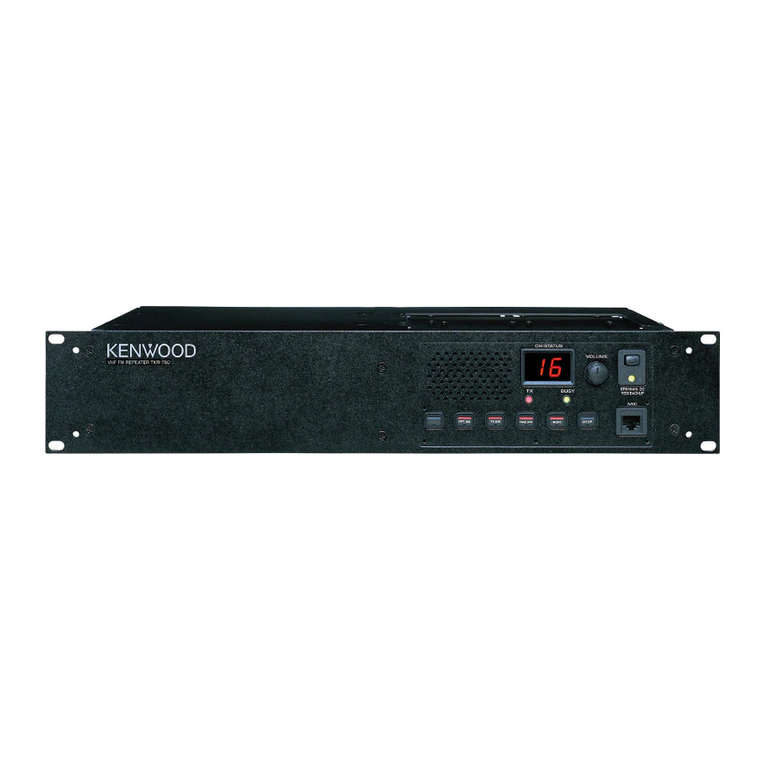
Yaesu VXR-7000U User manual

Yaesu
Yaesu FTR-710A User manual

Yaesu
Yaesu WIRES-X TM-400FT5D Installation and operation manual

Yaesu
Yaesu DR-1 User manual

Yaesu
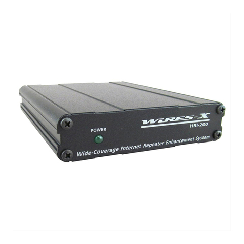
Yaesu WIRES-X HRI-200 User manual

Yaesu
Yaesu C4FM User manual

Yaesu
Yaesu WIRES-X HRI-200 User manual

Yaesu
Yaesu Wires-X User manual

Yaesu
Yaesu DR-1X User manual

Yaesu
Yaesu DR-2X User manual