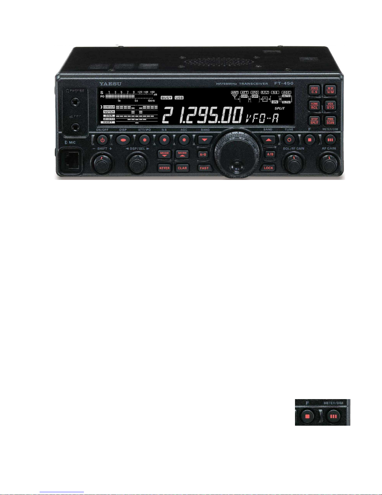
YAESU HF/50 mHz Transceiver FT-450 User’s Manual
- i -
Table of Contents
1General.....................................................................................................................................1
2Controls....................................................................................................................................1
2.1
Power ...............................................................................................................................3
3Receiver....................................................................................................................................4
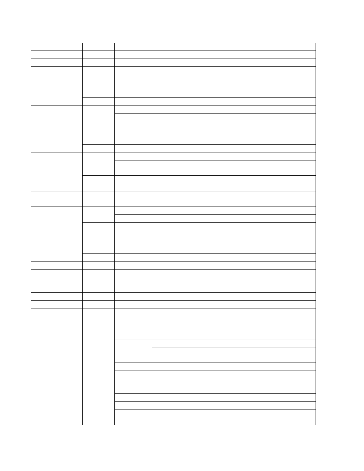
3.1 Communications Mode......................................................................................................4
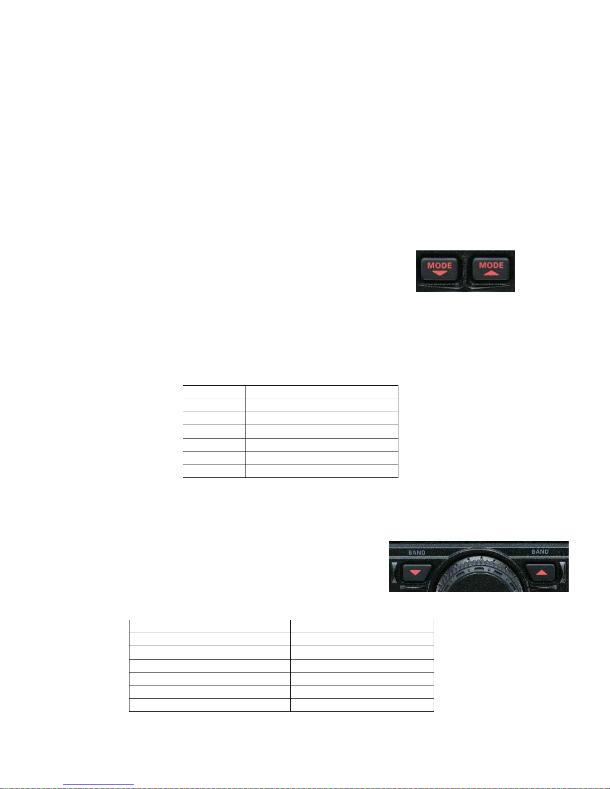
3.2 Band.................................................................................................................................4
3.3 VFO (Variable Frequency Oscillator)..................................................................................5
3.3.1 Clarifier ........................................................................................................................6
3.3.2
Split Frequency Operation..............................................................................................6
3.4 Extracting the Signal from the Noise...................................................................................7
3.4.1 RF Attenuation and Intercept Point Optimization (IPO)....................................................7
3.4.2 Noise Blanking..............................................................................................................7
3.4.3 Digital Signal Processor.................................................................................................7
3.4.3.1
Contour............................................................................................................8
3.4.3.2 Notch...............................................................................................................8
3.4.3.3 Digital Noise Reduction (DNR).......................................................................8
3.4.3.4
Band Pass Width.............................................................................................8
3.4.3.5 Filter Shift........................................................................................................9
3.4.4
CW Reverse..................................................................................................................9
3.4.4.6 CW Spotting....................................................................................................9
3.4.5 Radio Frequency Gain....................................................................................................9
3.4.5.7 Automatic Gain Control...................................................................................9
3.4.5.8 Radio Frequency Volume Control.................................................................10
3.4.6 Audio Volume Control..........................................................................................10
3.4.7 Signal meter................................................................................................................10
4Transmitter..............................................................................................................................10
4.1 Transmission...................................................................................................................11
4.1.1 Microphone Button......................................................................................................11
4.1.2 Voice Activated Transmitter Switching (VOX)..............................................................11
4.1.3 CW Break-In...............................................................................................................11
4.1.4 Data............................................................................................................................11
4.2 Meter..............................................................................................................................11
4.3 Automatic Antenna Tuner ................................................................................................12
5Channel Memories...................................................................................................................12
5.1 Memory Content..............................................................................................................12
5.2 Tuning of the VFO Setup Memory....................................................................................13
5.3 Band VFO Setup Memory................................................................................................14
5.4
Home Memory ................................................................................................................14
5.5 Quick Memory ................................................................................................................14
5.6 Channels Memories .........................................................................................................15
5.6.1 Recall .........................................................................................................................15
5.6.2 Storage........................................................................................................................15
5.6.3 Removal .....................................................................................................................15
5.6.4 Labeling......................................................................................................................15
5.7 VFO Memory Scanning ...................................................................................................16