Introduction ................................................................... 1
Warning! FCC RF Exposure Requirements ............... 2
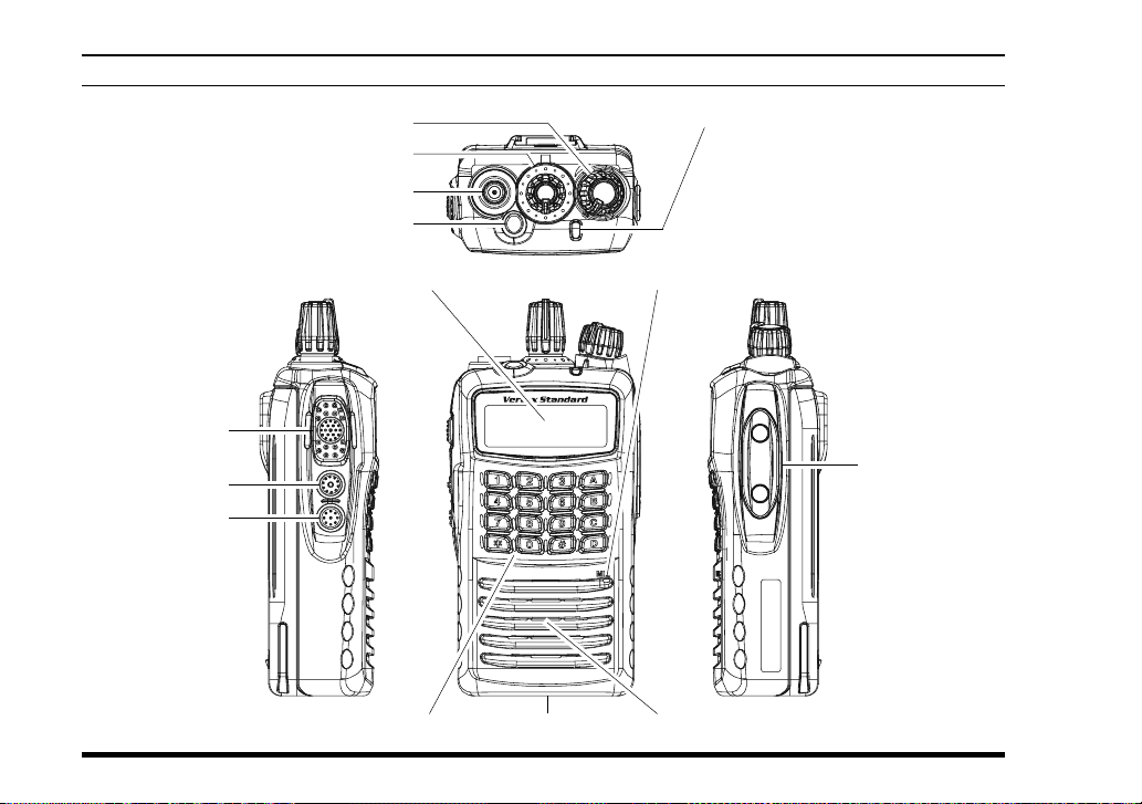
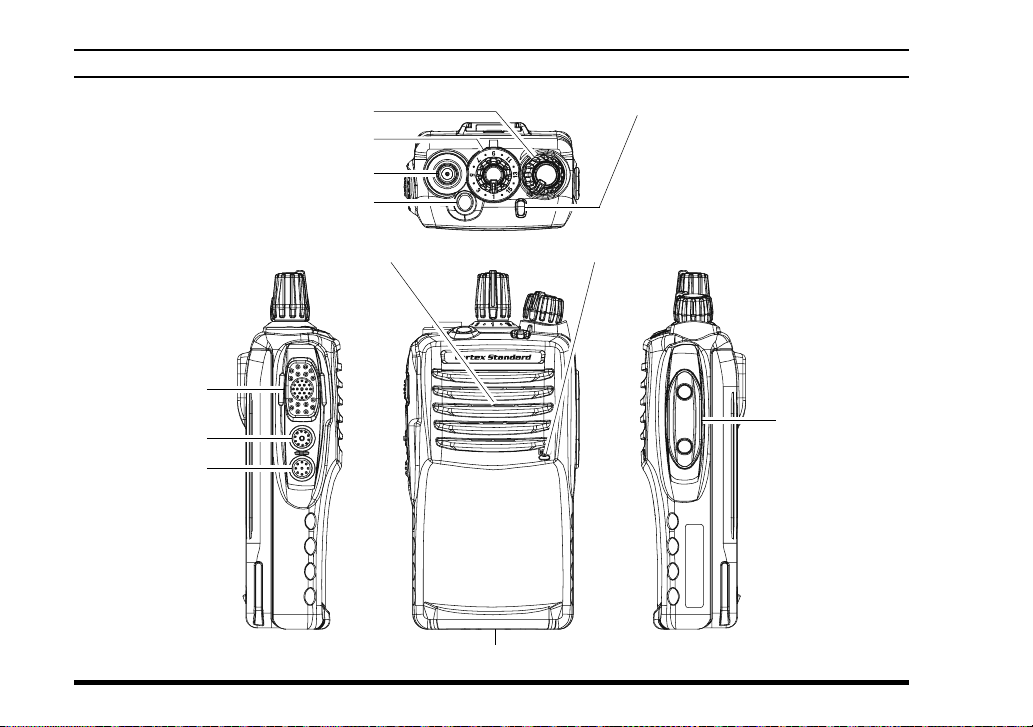
Controls & Connectors (VX-459) ................................ 4
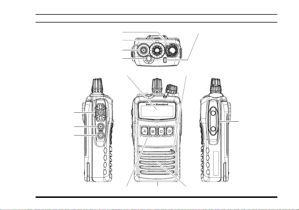
Controls & Connectors (VX-454) ................................ 5
Controls & Connectors (VX-451) ................................ 6
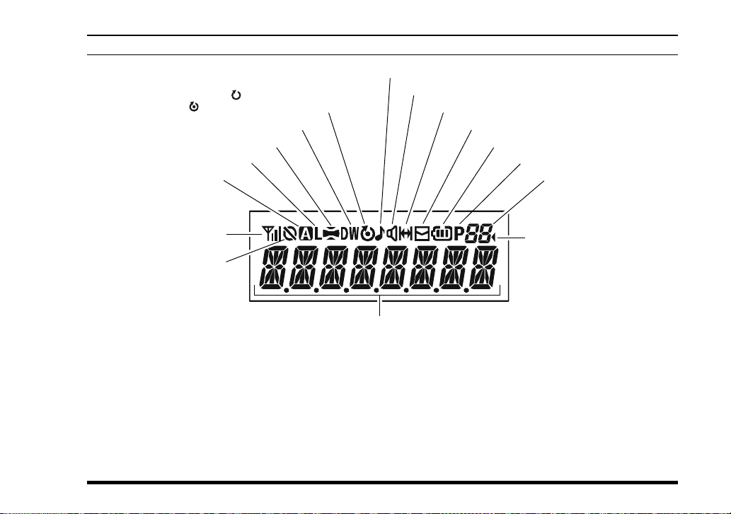
LCD Icons & Indicators (VX-454 & VX-459) ............ 7
Before You Begin ........................................................... 8
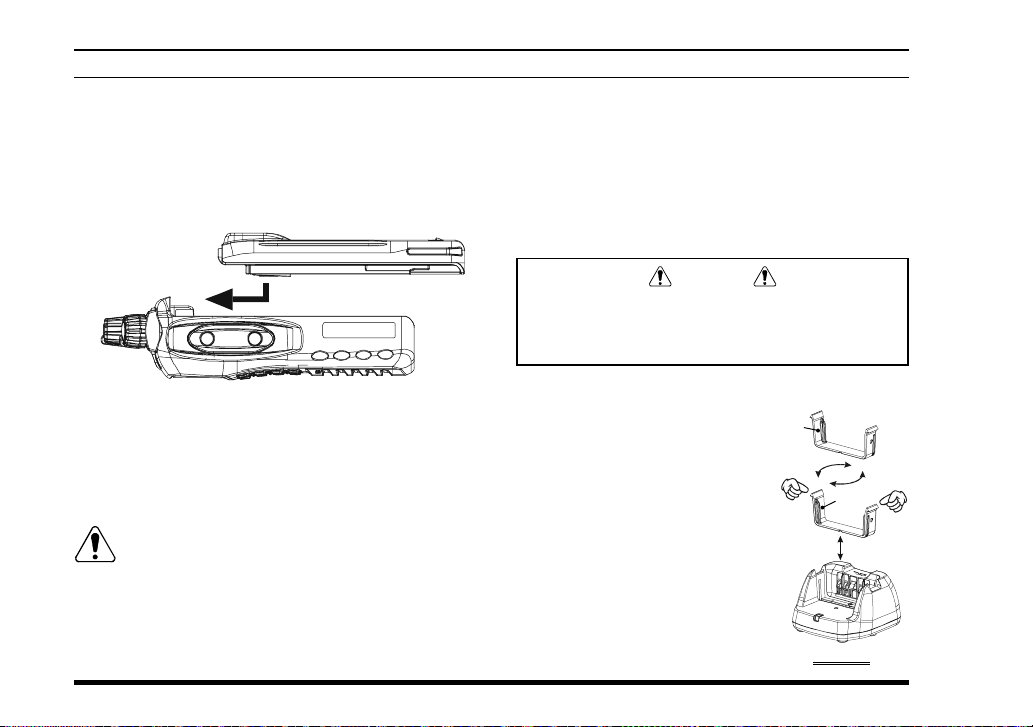
Battery Pack Installation and Removal...................... 8
Low Battery Indication .............................................. 8
Battery Charging........................................................ 8
Belt Clip Installation and Removal.......................... 10
Operation ..................................................................... 12
Preliminary Steps ..................................................... 12
Operation Quick Start .............................................. 12
Advanced Operation ................................................... 16
Programmable Key Functions ................................. 16
Description of Operating Functions ........................ 18
Man Down Function.................................................... 29
ARTS (Auto Range Transpond System) ................... 29
LOCK ........................................................................... 29
User Set Mode .............................................................. 30
OptionalAccessories.................................................... 31
CONTENTS
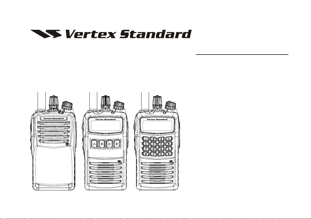
CONGRATULATIONS!
You now have at your fingertips a valuable communications tool-a Vertex Standard two-way radio! Rug-
ged, reliable and easy to use, your Vertex Standard radio will keep you in constant touch with your
colleagues for years to come, with negligible maintenance down-time. Please take a few minutes to read
this manual carefully. The information presented here will allow you to derive maximum performance
from your radio, in case questions arise later on.
We’re glad you joined the Vertex Standard team. Call on us anytime, because communications is our
business. Let us help you get your message across.
Notice!: There are no owner-serviceable parts inside the radio.All service jobs must be referred to an
authorized Vertex Standard Service Representative. Consult yourAuthorized Vertex Standard Dealer for
installation of optional accessories.