Yamaha PW5000 User manual

PW5000
1
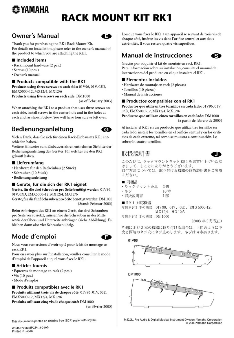
SERVICE MANUAL
PA 011697
Copyright (c) Yamaha Corporation. All rights reserved. ’03.09
HAMAMATSU, JAPAN
POWER SUPPLY
CONTENTS
SPECIFICATIONS ................................................... 3
PANEL LAYOUT .................................... 4
DIMENSIONS ............................................................ 5
CIRCUIT BOARD LAYOUT ................. 6
DISASSEMBLY PROCEDURE .............................. 7
IC BLOCK DIAGRAM .................................. 12
CIRCUIT BOARDS ....................................... 13
INSPECTIONS .......................................................19/22
PARTS LIST
POWER SUPPLY UNIT REPAIR MANUAL
BLOCK & CONNECTOR CIRCUIT DIAGRAM
CIRCUIT DIAGRAM
PW5000: 200307-480000
(目次)
(
総合仕様
)
(パネルレイアウト)
(寸法図) (ユニットレイアウト)
(分解手順)
(ICブロック図)
(シート基板図)
(検査)
(電源ユニット修理マニュアル)
(ブロック&コネクター回路図)
(回路図)
w
w
w
.
x
i
a
o
y
u
1
6
3
.
c
o
m
Q
Q
3
7
6
3
1
5
1
5
0
9
9
2
8
9
4
2
9
8
T
E
L
1
3
9
4
2
2
9
6
5
1
3
9
9
2
8
9
4
2
9
8
0
5
1
5
1
3
6
7
3
Q
Q
TEL 13942296513 QQ 376315150 892498299
http://www.xiaoyu163.com

PW5000
2
IMPORTANT NOTICE
This manual has been provided for the use of authorized Yamaha Retailers and their service personnel. It has been assumed
that basic service procedures inherent to the industry, and more specifically Yamaha Products, are already known and under-
stood by the users, and have therefore not been restated.
WARNING : Failure to follow appropriate service and safety procedures when servicing this product may result in per-
sonal injury, destruction of expensive components and failure of the product to perform as specified. For
these reasons, we advise all Yamaha product owners that all service required should be performed by an
authorized Yamaha Retailer or the appointed service representative.
IMPORTANT : This presentation or sale of this manual to any individual or firm does not constitute authorization certifi-
cation, recognition of any applicable technical capabilities, or establish a principal-agent relationship of
any form.
The data provided is belived to be accurate and applicable to the unit(s) indicated on the cover. The research engineering, and
service departments of Yamaha are continually striving to improve Yamaha products. Modifications are, therefore, inevitable
and changes in specification are subject to change without notice or obligation to retrofit. Should any discrepancy appear to
exist, please contact the distributor’s Service Division.
WARNING : Static discharges can destroy expensive components. Discharge any static electricity your body may have
accumulated by grounding yourself to the ground bus in the unit (heavy gauge black wires connect to
this bus.)
IMPORTANT : Turn the unit OFF during disassembly and parts replacement. Recheck all work before you apply power
to the unit.
WARNING: CHEMICAL CONTENT NOTICE!
The solder used in the production of this product contains LEAD. In addition, other electrical/electronic and/or plastic (Where
applicable) components may also contain traces of chemicals found by the California Health and Welfare Agency (and possibly
other entities) to cause cancer and/or birth defects or other reproductive harm.
DO NOT PLACE SOLDER, ELECTRICAL/ELECTRONIC OR PLASTIC COMPONENTS IN YOUR MOUTH FOR ANY REASON WHAT
SO EVER!
Avoid prolonged, unprotected contact between solder and your skin! When soldering, do not inhale solder fumes or expose
eyes to solder/flux vapor!
If you come in contact with solder or components located inside the enclosure of this product, wash your hands before handling
food.
WARNING
Components having special characteristics are marked and must be replaced with parts having specification equal to those
originally installed.
IMPORTANT NOTICE FORTHE UNITED KINGDOM
Connecting the Plug and Cord
WARNING: THIS APPARATUS MUST BE EARTHED
IMPORTANT. The wires in this mains lead are coloured in accordance
with the following code:
GREEN-AND-YELLOW : EARTH
BLUE : NEUTRAL
BROWN : LIVE
As the colours of the wires in the mains lead of this apparatus may not
correspond with the coloured markings identifying the terminals in
your plug proceed as follows:
The wire which is coloured GREEN-and-YELLOW must be connected
to the terminal in the plug which is marked by the letter E or by the
safety earth symbol or colored GREEN or GREEN-and-YELLOW.
The wire which is coloured BLUE must be connected to the terminal
which is marked with the letter N or coloured BLACK.
The wire which is coloured BROWN must be connected to the termi-
nal which is marked with the letter L or coloured RED.
• This applies only to products distributed byYamaha-Kemble Music (U.K.) Ltd. (3 wires)
印の商品は、安全を維持するために重要な部品です。交換する場合は、安全のために必ず指定の部品をご使用ください。
w
w
w
.
x
i
a
o
y
u
1
6
3
.
c
o
m
Q
Q
3
7
6
3
1
5
1
5
0
9
9
2
8
9
4
2
9
8
T
E
L
1
3
9
4
2
2
9
6
5
1
3
9
9
2
8
9
4
2
9
8
0
5
1
5
1
3
6
7
3
Q
Q
TEL 13942296513 QQ 376315150 892498299
http://www.xiaoyu163.com

PW5000
3
SPECIFICATIONS
General Specifications
Power Supply U.S./Canada: 120 V, 60 Hz
Australia: 240 V, 50 Hz
Other: 230 V, 50 Hz
Power Consumption U.S./Canada: 1100 W, 1250 VA
Other: 1100W
Dimensions (W x H x D) 480 mm x 186 mm x 459 mm
Weight 34 kg
Cooling Fan Speed Settings HIGH (continuous operation at max.),
AUTO (3-speed automatic)
一般仕様
電源 100V,50/60Hz
消費電力 1100W
外形寸法(WxHxD) 480mm×186mm×459mm
質量 34kg
冷却ファン速度 HIGH(常時最高速度),AUTO(3段階で変速)
Power Connector Pin Diagram (DC OUTPUT)
* DC OUTPUT connector as seen from the rear panel.
DC PARALLEL INPUT pin assignments are flipped
horizontally.
Power Supply Cable Pin Assignments
123
4567
8
9101112
131415161718
1920
24
25
27
26
212223
No. Function No. Function
1 -16V 15 +16V
2 -16V 16 ±16V GND
3 FRAME GND 17 +12V GND
4 -16V 18 +12V GND
5 -16V 19 +48V
6±16V GND 20 PW CAUTION
7 +12V GND 21 ±16V GND
8 REMOTE 22 +12V
9 +16V 23 +12V
10 +16V 24 +48V GND
11 ±16V GND 25 +12V
12 +12V GND 26 +12V
13 REMOTE 27 +12V
14 +16V
(DCOUTPUTコネクターをリアパネルから見た図です。
DCPARALLELINPUTコネクターは、ピン配列が左右
反対になります。)
(電源コネクターの形状(DCOUTPUT)) (電源ケーブルのピン配列)
(総合仕様)
w
w
w
.
x
i
a
o
y
u
1
6
3
.
c
o
m
Q
Q
3
7
6
3
1
5
1
5
0
9
9
2
8
9
4
2
9
8
T
E
L
1
3
9
4
2
2
9
6
5
1
3
9
9
2
8
9
4
2
9
8
0
5
1
5
1
3
6
7
3
Q
Q
TEL 13942296513 QQ 376315150 892498299
http://www.xiaoyu163.com
PW5000
4
PANEL LAYOUT
q[POWER ON/OFF] Switch
wOPERATION MONITOR
e[HIGH] Indicator
r[STOP] Indicator
t[THERMAL] Indicator
yLINE VOLTAGE Display
u[FAN SPEED] Switch
Front Panel(フロントパネル)
NORMAL
CAUTION
+16 -16 +12 +48
HIGH
STOP THERMAL
POWER
ON OFF
OPERATION MONITOR FAN LINE VOLTAGE
FAN SPEED
AUTO HIGH
POWER SUPPLY
Rear Panel(リアパネル)
13.5A
13.5A
14.0A
1.0A
5000
9,10,14,15
1,2,4,5
22,23,25,26,27
19
(パネルレイアウト)
([POWERON/OFF]スイッチ)
(OPERATIONMONITOR)
([HIGH]インジケーター)
([STOP]インジケーター)
([THERMAL]インジケーター)
(LINEVOLTAGE)
([FANSPEED]スイッチ)
i[DC PARALLEL INPUT] Connector
o[DC OUTPUT] Connector
!0 EARTH ScrewTerminal
([DCPARALLELINPUT]コネクター)
([DCOUTPUT]コネクター)
(アース用ネジ)
w
w
w
.
x
i
a
o
y
u
1
6
3
.
c
o
m
Q
Q
3
7
6
3
1
5
1
5
0
9
9
2
8
9
4
2
9
8
T
E
L
1
3
9
4
2
2
9
6
5
1
3
9
9
2
8
9
4
2
9
8
0
5
1
5
1
3
6
7
3
Q
Q
TEL 13942296513 QQ 376315150 892498299
http://www.xiaoyu163.com

PW5000
6
<Top view>
<Front view><Left side view>
AC 1/3
DC
Power supply unit
(電源ユニット) DC unit
(DCユニット)
AC 3/3
PN 1/2
AC 2/3
PN 2/2
PN 1/2
PN 2/2
CIRCUIT BOARD LAYOUT
(ユニットレイアウト)
w
w
w
.
x
i
a
o
y
u
1
6
3
.
c
o
m
Q
Q
3
7
6
3
1
5
1
5
0
9
9
2
8
9
4
2
9
8
T
E
L
1
3
9
4
2
2
9
6
5
1
3
9
9
2
8
9
4
2
9
8
0
5
1
5
1
3
6
7
3
Q
Q
TEL 13942296513 QQ 376315150 892498299
http://www.xiaoyu163.com

7
PW5000
DISASSEMBLY PROCEDURE
1. トップカバー(所要時間:約 2 分)
1-1 [270A]のネジ 11 本を外し、トップカバーを外しま
す。(図 1)
[270A]
[120]
[120] [120]
[130] [130]
[270A]
[270A]
[200A]
[200C] [200C] [200C]
[310]
[310]
[200B]
[170]
[170]
[180]
[180]
[170] [150] [150]
[150]
[150]
[150]
[270A]
[270A]
(トップカバー)
(マウントサポートパネル)
Frontpanelassembly
(フロントパネルAss'y)
Powerswitchknob(PSWノブ)
Rearassembly(リアAss'y)
Mountsupportpanel
(サイドパネルL)
SidepanelL
(サイドパネルR)
SidepanelR
(マウントサポートパネル)
Mountsupportpanel
<Top view>
<Rear view>
<Left side view> <Right side view>
<Front view>
Topcover
[120]: Flat Head Tapping Screw-B 4.0X10 MFZN2BL (VP063700)
[130]: Bind Head Tapping Screw-B 4.0X8 MFZN2BL (EG340190)
[150]: Bind Head Tapping Screw-B 4.0X8 MFZN2BL (EG340190)
[170]: Bind Head Tapping Screw-B 4.0X8 MFZN2BL (EG340190)
[180]: Bind Head Screw 4.0X6 MFZN2BL (EG340340)
[200]: Bind Head Tapping Screw-B 4.0X8 MFZN2BL (EG340190)
[270A]: Bind Head Screw 4.0X6 MFZN2BL (EG340340)
[310]: Bind Head Screw A4.0X8 MFZN2BL (VP156800)
Fig. 1
1. Top Cover
(Time required: About 2 minutes)
1-1 Remove the eleven (11) screws marked [270A].The
top cover can then be removed. (Fig.1)
(分解手順)
(+皿Bタイト)
(+バインドBタイト)
(+バインドBタイト)
(+バインドBタイト)
(+バインド小ネジ)
(+バインドBタイト)
(+バインド小ネジ)
(+バインド小ネジ)
(図1)
w
w
w
.
x
i
a
o
y
u
1
6
3
.
c
o
m
Q
Q
3
7
6
3
1
5
1
5
0
9
9
2
8
9
4
2
9
8
T
E
L
1
3
9
4
2
2
9
6
5
1
3
9
9
2
8
9
4
2
9
8
0
5
1
5
1
3
6
7
3
Q
Q
TEL 13942296513 QQ 376315150 892498299
http://www.xiaoyu163.com

PW5000
8
2. フロントパネル Assy(所要時間:約 2 分)
2-1 [120]のネジ 6 本と[130]のネジ 6 本を外し、フロン
トパネル Assy を外します。(図 1)
3. PN1/2、PN2/2シート(所要時間:各約3分)
3-1 フロントパネル Assy を外します。(2項参照)
3-2 PN1/2シート:
3-2-1 [30]のネジ4 本を外し、PN1/2シートを外します。
(図 2)
3-3 PN2/2シート:
3-3-1 PSWノブを外します。(図 1)
3-3-2 [40A]のネジ2本を外し、PN2/2シートを外します。
(図 2)
<Front view>
PN 1/2
PN 2/2
[40A]
[40A][30]
[30]
4. サイドパネルL(所要時間:約 4 分)
4-1 トップカバーを外します。(1 項参照)
4-2 [170]のネジ5本と[180]のネジ4本、[200A]のネジ2
本を外し、マウントサポートパネルと共にサイドパ
ネル L を外します。(図 1)
5. 電源ユニット(所要時間:約 5 分)
5-1 トップカバーを外します。(1 項参照)
5-2 サイドパネル L を外します。(4 項参照)
5-3 [270B]のネジ2 本を外し、電源ユニットを外しま
す。(図 3)
[30]: Bind Head Tapping Screw-B 3.0X6 MFZN2BL (EP600230)
[40A]: Bind Head Screw 3.0X8 MFZN2BL (VB659000)
Fig. 2 (図2)
2. Front Panel Assembly
(Time required: About 2 minutes)
2-1 Remove the six (6) screws marked [120] and the six
(6) screws marked [130].The front panel assembly
can then be removed. (Fig.1)
3. PN 1/2, PN 2/2 Circuit Boards
(Time required: About 3 minutes each)
3-1 Remove the front panel assembly.(See procedure 2.)
3-2 PN 1/2 circuit board:
3-2-1 Remove the four (4) screws marked [30].The PN 1/2
circuit board can then be removed. (Fig.2)
3-3 PN 2/2 circuit board:
3-3-1 Remove the power switch knob.(Fig.1)
3-3-2 Remove the two (2) screws marked [40A].The PN
2/2 circuit board can then be removed. (Fig.2)
4. Side Panel L
(Time required: About 4 minutes)
4-1 Remove the top cover.(See procedure 1.)
4-2 Remove the five (5) screws marked [170] and the
four (4) screws marked [180], the two (2) screws
marked [200A]. The side panel L can then be
removed with the mount support panel. (Fig.1)
5. Power supply unit
(Time required: About 5 minutes)
5-1 Remove the top cover.(See procedure 1.)
5-2 Remove the side panel L.(See procedure 4.)
5-3 Remove the two (2) screws marked [270B]. The
power supply unit can then be removed.(Fig.3)
(+バインドBタイト)
(+バインド小ネジ)
w
w
w
.
x
i
a
o
y
u
1
6
3
.
c
o
m
Q
Q
3
7
6
3
1
5
1
5
0
9
9
2
8
9
4
2
9
8
T
E
L
1
3
9
4
2
2
9
6
5
1
3
9
9
2
8
9
4
2
9
8
0
5
1
5
1
3
6
7
3
Q
Q
TEL 13942296513 QQ 376315150 892498299
http://www.xiaoyu163.com
9
PW5000
6. サイドパネル R(所要時間:約 4 分)
6-1 トップカバーを外します。(1項参照)
6-2 [150]のネジ8 本と[200B]のネジ2本を外し、マウン
トサポートパネルと共にサイドパネル R を外しま
す。(図 1)
7. DCユニット、DCシート(所要時間:約9分)
7-1 トップカバーを外します。(1項参照)
7-2 サイドパネル R を外します。(6 項参照)
7-3 [45]のネジ 3 本を外し、DC ユニットを外します。
(図 3)
7-4 [40B]のネジ5本と[60]のネジ14本、[90]のネジ3本
を外し、DC ユニットから DC シートを外します。
(図 4)
<Top view>
[45]
[270B]
(電源ユニット)
Powersupplyunit
[270B]
(DCユニット)
DCunit
Fig. 3
[45]: Bind Head Tapping Screw-B 4.0X10 MFZN2BL (EP600240)
[270B]: Bind Head Tapping Screw-B 4.0X8 MFZN2BL (EG340190)
6. Side Panel R
(Time required: About 4 minutes)
6-1 Remove the top cover.(See procedure 1.)
6-2 Remove the eight (8) screws marked [150] and the
two (2) screws marked [200B].The side panel R can
then be removed with the mount support panel.
(Fig.1)
7. DC Unit, DC circuit board
(Time required: About 9 minutes)
7-1 Remove the top cover.(See procedure 1.)
7-2 Remove the side panel R.(See procedure 6.)
7-3 Remove the three (3) screws marked [45].The DC
unit can then be removed. (Fig.3)
7-4 Remove the five (5) screws marked [40B], the
fourteen (14) screws marked [60] and the three (3)
screws marked [90].The DC circuit board can then
be removed from the DC unit. (Fig.4)
(図3)
(+バインドBタイト)
(+バインドBタイト)
w
w
w
.
x
i
a
o
y
u
1
6
3
.
c
o
m
Q
Q
3
7
6
3
1
5
1
5
0
9
9
2
8
9
4
2
9
8
T
E
L
1
3
9
4
2
2
9
6
5
1
3
9
9
2
8
9
4
2
9
8
0
5
1
5
1
3
6
7
3
Q
Q
TEL 13942296513 QQ 376315150 892498299
http://www.xiaoyu163.com
PW5000
10
(DCユニット
)
DCunit(DCユニット)DCunit
<Left side view>
<Front view>
[40B]
[60][60]
[90]
[40B]
[40B] [40B]
[40B]
[60]
DC DC
8. リアAssy(所要時間:約 4 分)
8-1 トップカバーを外します。(1 項参照)
8-2 [200A]のネジ 2 本と[200B]のネジ 2 本、[200C]のネ
ジ3本、[310]のネジ 3 本を外します。(図 1)
8-3 AC1/3 シート K101,K102 からAC ケーブルを外し
て、リア Assy を外します。(図 5)
9. AC1/3シート(所要時間:約 5 分)
9-1 トップカバーを外します。(1 項参照)
9-2 リア Assy を外します。(8項参照)
9-3 [70]のネジ6本を外し、AC1/3シートを外します。
(図 5)
10. AC2/3、AC3/3シート(所要時間:各約3分)
10-1 トップカバーを外します。(1 項参照)
10-2 [160]のネジ4本と[320]のネジ1本を外し、DS金具
を外します。(図 5)
10-3 AC2/3シート:
10-3-1 [230A]のネジを外し、DS金具からAC2/3シートを
外します。(図 6)
10-4 AC3/3シート:
10-4-1 [230B]のネジを外し、DS金具からAC3/3シートを
外します。(図 6)
Fig. 4
[40B]: Bind Head Screw SP 3.0X8 MFZN2Y (EG330290)
[60]: Bind Head Screw SP 3.0X12 MFZN2Y (VB763800)
[90]: Bind Head Tapping Screw-B 3.0X6 MFZN2BL (EP600230)
8. Rear Assembly
(Time required: About 4 minutes)
8-1 Remove the top cover.(See procedure 1.)
8-2 Remove the two (2) screws marked [200A], the two
(2) screws marked [200B], the three (3) screws
marked [200C] and the three (3) screws marked
[310]. (Fig.1)
8-3 AC cable is removed from the AC 1/3 circuit board
K101 and K102. The rear assembly can then be
removed. (Fig.5)
9. AC 1/3 Circuit Board
(Time required: About 5 minutes)
9-1 Remove the top cover. (See procedure 1.)
9-2 Remove the rear assembly.(See procedure 8.)
9-3 Remove the six (6) screws marked [70].The AC 1/3
circuit board can then be removed. (Fig.5)
10. AC 2/3, AC 3/3 Circuit Boards
(Time required: About 3 minutes each)
10-1 Remove the top cover.(See procedure 1.)
10-2 Remove the four (4) screws marked [160] and the
screw marked [320]. The DS angle can then be
removed. (Fig.5)
10-3 AC 2/3 circuit board:
10-3-1 Remove the screw marked [230A].The AC 2/3 circuit
board can thenbe removed from the DS angle.(Fig.6)
10-4 AC 3/3 circuit board:
10-4-1 Remove the screw marked [230B].The AC 3/3 circuit
board can thenbe removed from the DS angle.(Fig.6)
(図4)
(+バインド小ネジ)
(+バインド小ネジ)
(+バインドBタイト)
w
w
w
.
x
i
a
o
y
u
1
6
3
.
c
o
m
Q
Q
3
7
6
3
1
5
1
5
0
9
9
2
8
9
4
2
9
8
T
E
L
1
3
9
4
2
2
9
6
5
1
3
9
9
2
8
9
4
2
9
8
0
5
1
5
1
3
6
7
3
Q
Q
TEL 13942296513 QQ 376315150 892498299
http://www.xiaoyu163.com
11
PW5000
[160]
[160] [320]
(DS金具)
DSangle
(ACケーブル)ACcable
<Top view>
[70] [70]
K101
AC 1/3 AC 2/3
AC 3/3
K102
(ヒートシンク)
Heatsink
(DS金具)DSangle
<Front view>
[230
A]
[230B]
AC 2/3AC 3/3
[70]: Bind Head Tapping Screw-B 3.0X6 MFZN2BL (EP600230)
[160]: Bind Head Tapping Screw-B 4.0X10 MFZN2BL (EP600240)
[320]: Bind Head Tapping Screw-B 3.0X6 MFZN2BL (EP600230)
Fig. 5
[230]: Bind Head Tapping Screw-B 4.0X12 MFZN2BL (VR138400)
Fig. 6 (図6)
(+バインドBタイト)
(+バインドBタイト)
(+バインドBタイト)
(図5)
(+バインドBタイト)
w
w
w
.
x
i
a
o
y
u
1
6
3
.
c
o
m
Q
Q
3
7
6
3
1
5
1
5
0
9
9
2
8
9
4
2
9
8
T
E
L
1
3
9
4
2
2
9
6
5
1
3
9
9
2
8
9
4
2
9
8
0
5
1
5
1
3
6
7
3
Q
Q
TEL 13942296513 QQ 376315150 892498299
http://www.xiaoyu163.com
PW5000
12
IC BLOCK DIAGRAM(IC ブロック図)
TC74HC04AP (IR000400)
PW5K PN 1/2: IC307
Hex Inverter
TC74HC08AP (IR000800)
PW5K PN 1/2: IC309,310,313,314
Quad 2 Input AND
TC74HC14AP (IR001400)
PW5K PN 1/2: IC312
Hex Inverter
SN74HC21N (IR002150)
PW5K PN 1/2: IC311
Dual 4 Input AND
SN74HC563N (IR056350)
PW5K PN 1/2: IC317
Octal D-Type Latch
SN74HC573N (IR057350)
PW5K PN 1/2: IC316
Octal 3-State D-Latches
TC74HC4066AP (IR406600)
PW5K PN 1/2: IC308
Quad Bilateral Analog Switch
NJM2901N (IG036100)
PW5K PN 1/2: IC305,306
Comparator
NJM2041D-D (IG069200)
PW5K DC: IC201,202
Dual Operational Amplifier
1
2
3
4
5
6
7
1A
1Y
2A
2Y
3A
3Y
Vss
14
13
12
11
10
9
8
VDD
6A
6Y
5A
5Y
4A
4Y
1
2
3
1A
1B
1Y
2A
2B
4
2Y
5
VSS
VDD
4B
4A
4Y
3B
3A
3Y
6
7
14
13
12
11
10
9
8
1
1A
2
1Y
3
2A
4
2Y
5
3A
6
3Y
7
GND
14
VDD
13
6A
12
6Y
11
5A
10
5Y
9
4A
8
4Y
1
2
3
1A
NC
4
1C
5
1D
6
1Y
7
GND
1B
14
13
12
Vcc
2C
11
NC
10
2B
9
2A
8
2Y
2D
10
9
8
7
6
5
4
3
2
1
D6
D
CQ
OE
D
CQ
OE
D
CQ
OE
D
CQ
OE
D
CQ
OE
D
CQ
OE
D
CQ
OE
D
CQ
OE
D7
D8
GND
D5
D4
D3
D2
D1
Output
Control
Q6
Q7
Q8
Clock
Q5
Q4
Q3
Q2
Q1
Vcc
11
12
13
14
15
16
17
18
19
20
10
9
8
7
6
5
4
3
2
1
D5
D6
D7
GND
D4
D3
D2
D1
D0
OE
Q5
Q6
Q7
LE
Q4
Q3
Q2
Q1
Q0
Vcc
11
12
13
14
15
16
17
18
19
20
EN
C1
1D
(1)
(11)
(2)
(3)
(19)
(18)
(4) (17)
(5) (16)
(6) (15)
(7) (14)
(8) (13)
(9) (12)
1
2
3
4
5
6
7
IN/OUT 1
OUT/IN 1
OUT/IN 2
IN/OUT 2
Control 2
Control 3
VSS
14
13
12
11
10
9
8
VDD
Control 1
Control 4
IN/OUT 4
OUT/IN 4
OUT/IN 3
IN/OUT 3
1
B OUTPUT
2
3
4
5
6
7
A OUTPUT
V +
A - INPUT
A + INPUT
B - INPUT
8
9
10
11
12
13
14
C OUTPUT
D OUTPUT
GND
D + INPUT
D - INPUT
C + INPUT
C - INPUT
B + INPUT
+-+-
+-+-
1
2
3
4-V
8
7
6
5
Output A
+V
Non-Inverting
Input A
-DC Voltage Supply
+DC Voltage
Supply
Output B
Inverting
Input B
Non-Inverting
Input B
Inverting
Input A
+-
+-
w
w
w
.
x
i
a
o
y
u
1
6
3
.
c
o
m
Q
Q
3
7
6
3
1
5
1
5
0
9
9
2
8
9
4
2
9
8
T
E
L
1
3
9
4
2
2
9
6
5
1
3
9
9
2
8
9
4
2
9
8
0
5
1
5
1
3
6
7
3
Q
Q
TEL 13942296513 QQ 376315150 892498299
http://www.xiaoyu163.com
PW5000
13
to Power supply unit to Power supply unit
to DC OUTPUT
to DC PARALLEL INPUT
to PN 1/2-CN304
to PN 1/2-CN307
to Power supply unit
to Power transformer
(±16V)
to Power transformer
(INDI)
to Power transformer
(SUB12V)
to PN 2/2-CN401
to PN 1/2
-CN302
to PN 1/2
-CN303
AC 1/3 Circuit Board
CIRCUIT BOARDS
Note: See parts list for details of circuit board component parts.
AC 1/3, 2/3, 3/3 Circuit Board (X2605B0)................................ 13/14
DC Circuit Board (X2607B0)..................................................... 15/16
PN 1/2, 2/2 Circuit Board (X2606B0) ....................................... 17/18
注:シートの部品詳細はパーツリストをご参照ください。
Component side
AC 2/3 Circuit Board AC 3/3 Circuit Board
Component side(部品側) Component side(部品側)
2NAP-V994990-2 1
(シート基板図)
(部品側)
w
w
w
.
x
i
a
o
y
u
1
6
3
.
c
o
m
Q
Q
3
7
6
3
1
5
1
5
0
9
9
2
8
9
4
2
9
8
T
E
L
1
3
9
4
2
2
9
6
5
1
3
9
9
2
8
9
4
2
9
8
0
5
1
5
1
3
6
7
3
Q
Q
TEL 13942296513 QQ 376315150 892498299
http://www.xiaoyu163.com

PW5000
14
Pattern side(パターン側)
to DC-CN203
to Power transformer (±16V)to DC-CN201
to Power transformer (±16V)
to DC-CN203
to Power transformer (±16V)to DC-CN201
to Power transformer (±16V)
AC 1/3 Circuit Board
AC 2/3 Circuit Board AC 3/3 Circuit Board
Pattern side(パターン側)
Pattern side(パターン側)
2NAP-V994990-3 1
w
w
w
.
x
i
a
o
y
u
1
6
3
.
c
o
m
Q
Q
3
7
6
3
1
5
1
5
0
9
9
2
8
9
4
2
9
8
T
E
L
1
3
9
4
2
2
9
6
5
1
3
9
9
2
8
9
4
2
9
8
0
5
1
5
1
3
6
7
3
Q
Q
TEL 13942296513 QQ 376315150 892498299
http://www.xiaoyu163.com

PW5000
15
DC Circuit Board
2NAP-V994910-2 1Component side(部品側)
to DC PARALLEL INPUT
to DC OUTPUT
to PN 1/2-CN306
to PN 1/2-CN305
to AC 2/3-K504
to AC 3/3-K508
to Power transformer (±16V)
to AC 2/3-K503
to AC 3/3-K507
to DC OUTPUT
w
w
w
.
x
i
a
o
y
u
1
6
3
.
c
o
m
Q
Q
3
7
6
3
1
5
1
5
0
9
9
2
8
9
4
2
9
8
T
E
L
1
3
9
4
2
2
9
6
5
1
3
9
9
2
8
9
4
2
9
8
0
5
1
5
1
3
6
7
3
Q
Q
TEL 13942296513 QQ 376315150 892498299
http://www.xiaoyu163.com
PW5000
16
Pattern side(パターン側) 2NAP-V994910-2 1
DC Circuit Board
Connector assembly: WC414100
Connector assembly: WC414200
w
w
w
.
x
i
a
o
y
u
1
6
3
.
c
o
m
Q
Q
3
7
6
3
1
5
1
5
0
9
9
2
8
9
4
2
9
8
T
E
L
1
3
9
4
2
2
9
6
5
1
3
9
9
2
8
9
4
2
9
8
0
5
1
5
1
3
6
7
3
Q
Q
TEL 13942296513 QQ 376315150 892498299
http://www.xiaoyu163.com

PW5000
17
to FAN
to DC PARALLEL INPUT
to DC OUTPUT
to AC 1/3-CN106
POWER ON/OFF
FAN SPEED AUTO/HIGH
POWER ON/OFF
FAN HIGH
NORMAL +16 NORMAL -16 NORMAL +12 NORMAL +48
FAN STOPCAUTION +16 CAUTION +12 CAUTION +48CAUTION -16
THERMAL
LINE VOLTAGE
to AC 1/3-CN112
to DC-CN206 to AC 3/3-CN502
to DC-CN209 to AC 1/3-CN109
to AC 1/3-CN107
to Power transformer
(INDI)
to FAN
PN 1/2 Circuit Board
PN 2/2 Circuit Board
2NAP-V995010-2 2
Component side(部品側)
Component side(部品側)
w
w
w
.
x
i
a
o
y
u
1
6
3
.
c
o
m
Q
Q
3
7
6
3
1
5
1
5
0
9
9
2
8
9
4
2
9
8
T
E
L
1
3
9
4
2
2
9
6
5
1
3
9
9
2
8
9
4
2
9
8
0
5
1
5
1
3
6
7
3
Q
Q
TEL 13942296513 QQ 376315150 892498299
http://www.xiaoyu163.com
PW5000
18
PN 1/2 Circuit Board
PN 2/2 Circuit Board
Pattern side(パターン側)
Pattern side(パターン側)
2NAP-V995010-2 2
w
w
w
.
x
i
a
o
y
u
1
6
3
.
c
o
m
Q
Q
3
7
6
3
1
5
1
5
0
9
9
2
8
9
4
2
9
8
T
E
L
1
3
9
4
2
2
9
6
5
1
3
9
9
2
8
9
4
2
9
8
0
5
1
5
1
3
6
7
3
Q
Q
TEL 13942296513 QQ 376315150 892498299
http://www.xiaoyu163.com

19
PW5000
INSPECTIONS
1. Setup
If using a variable voltage transformer in the AC power supply, check for distortion on the AC waveform.
1
2
3
45
6
7
8
9
10
11
12 13
14
15
16
17
18 19
20
21
22
23 24
25
26
27
+48VGND
REMOTE 3 : FG
6,11,16,21: –16VGND
7,12,17,18: +12VGND
8,13: REMOTE
To make the PW5000 operation checks, setup the connector (shorting pins) shown in FIG. 1,
and the voltage check connector as shown in FIG. 2.
Short pin----- Connect to the DC OUTPUT
Fig. 1
Connector (female) : VP012200
(Solder terminal side)
123
4567
8910 11 12
13 14 15 16 17 18
19 20 21 22 23
24 25 26 27
Voltage measurement connector (measurement points) --- connect to DC PARALLEL INPUT
Fig. 2
(Solder terminal side)
-16V –16VGND
+16V
+48VGND
+48V
+12VGND
+12V
Connector (male) : VP012100
1: -16V
6: –16VGND
9: +16V
18: -12VGND
19: +48V
24: +48VGND
25: +12V
w
w
w
.
x
i
a
o
y
u
1
6
3
.
c
o
m
Q
Q
3
7
6
3
1
5
1
5
0
9
9
2
8
9
4
2
9
8
T
E
L
1
3
9
4
2
2
9
6
5
1
3
9
9
2
8
9
4
2
9
8
0
5
1
5
1
3
6
7
3
Q
Q
TEL 13942296513 QQ 376315150 892498299
http://www.xiaoyu163.com

PW5000
20
2. Structure
·Power supply circuits ±16 volts, +12 volts, +48 volts
·Safeguard circuits
·Primary power supply voltage (LINE VOLTAGE) display circuit (hereafter, listed as LV)
3. Electrical Performance
3-1 Checking operation
3-1-1 Check LV circuit operation
Check that the LV is displayed simultaneous with turning the primary power on, regardless of whether the power supply
switch is ON or OFF.
3-1-2 Check operation under no-load
①Check that the shorting pins are not connected to the DC OUTPUT.
·Check that turning on the power supply switch lights up the “POWER” LED (green) and the fan rotates. Also check
that there is no operating noise from the power relay and that the “CAUTION (red)”, “STOP (red)”, and “THERMAL
(red) all light up (total 6 locations) about 4 ±2 seconds after the power switch is turned on.
②Connect the shorting pin to the DC OUTPUT.
·Check that the “POWER” LED (green) lights up simultaneous with turning on the power supply switch, and that the
fans (2 units) start rotating.
·Check that all 4 of the voltage display LED “NORMAL” (green) light up 4 ±2 seconds after the power switch is turned on.
·Check that the fan rotates at low speed, when the“FAN AUTO/HIGH”switch is set to the “AUTO”side.Check that the
fan rotates at high speed and the “HIGH” LED lights up when the fan switch is set the “HIGH” side.
When finished checking the above “FAN AUTO/HIGH” switch, return the switch to the “AUTO” position.
See Page 21 on Fig. 3 to find the LED lighting locations.
3-1-3 Checking voltage output from the power supply circuits +12 volt line, +48 volt line, +16 volt line,
-16 volt line.
1) +12 volt line
Check that approximately +13 volts is supplied from the voltage measurement connector (across +12V and +12VGND).
2) +48 volt line
Check that approximately +49 volts is supplied from the voltage measurement connector (across +48V and +48VGND).
3) +16 volt line
Check that approximately +17 volts is supplied from the voltage measurement connector (across +16V and ±16VGND).
4) -16 volt line
Check that approximately -17 volts is supplied from the voltage measurement connector (across -16V and ±16VGND).
3-1-4 Check operation of ±16 volt detector circuit
1. Check that about 4 ±2 seconds after power is turned on while the primary line (CN101 and CN102 of AC 1/3 circuit
board) of the ±16 volt supply is disconnected;among the 4 voltage display LED, the +16, -16 “CAUTION” LED lights
up (“NORMAL” LED of +12, +48 light up). Also check that the unit shuts down about 8 ±2 seconds after power is
turned on but that the two +16, -16 “CAUTION” LED and the “POWER” LED remain lit up.
2. Check that when power is turned on while the CN502 of AC 3/3 circuit board is removed, the 4 voltage display
“NORMAL” LED light up. Also check that the unit shuts down about 8 ±2 seconds after power is turned on, and that
only the “POWER” LED remains lit up.
3. Check that when power is turned on while CN209 of DC circuit board is removed, the fan “HIGH”LED lights up (Fan
itself also rotates at high speed). Also check that the 4 “NORMAL” LED, and the “THERMAL” LED light up about 4 ±
2 seconds after power is turned on. Further check that the unit shuts down about 8 ±2 seconds after power is turned
on, but that the “THERMAL”“HIGH” and “POWER” LED remain lit up.
After making the above checks, reinsert the connectors that were removed in each item to make the above checks.
w
w
w
.
x
i
a
o
y
u
1
6
3
.
c
o
m
Q
Q
3
7
6
3
1
5
1
5
0
9
9
2
8
9
4
2
9
8
T
E
L
1
3
9
4
2
2
9
6
5
1
3
9
9
2
8
9
4
2
9
8
0
5
1
5
1
3
6
7
3
Q
Q
TEL 13942296513 QQ 376315150 892498299
http://www.xiaoyu163.com
Other manuals for PW5000
1
Table of contents
Other Yamaha Power Supply manuals

Yamaha
Yamaha PW4000 User manual

Yamaha
Yamaha PW3000M User manual

Yamaha
Yamaha PW2000M User manual

Yamaha
Yamaha PW4000 User manual

Yamaha
Yamaha PW3000MA User manual

Yamaha
Yamaha PW1D User manual

Yamaha
Yamaha PW8 User manual

Yamaha
Yamaha PW800W User manual

Yamaha
Yamaha PW5000 User manual

Yamaha
Yamaha PW2000M User manual