9
PW8
4. AC1 シート(所要時間:約 3 分)
4-1 トップカバーを外します。(1 項参照 )
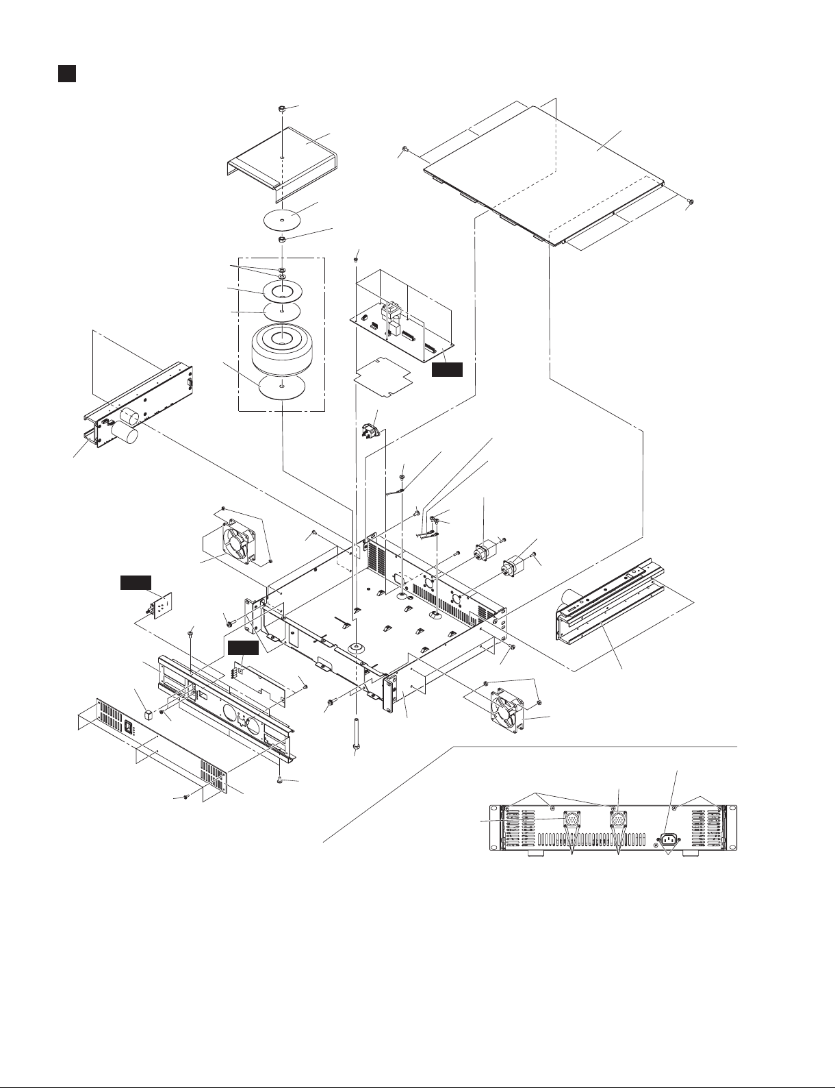
4-2 [300] のネジ 6 本を外し、AC1 シートを外します。
(図 1)
5. PS 束線
5-1 トップカバーを外します。(1 項参照 )
5-2 DCPARALLELINPUT(所要時間:約 3 分)
5-2-1 [380A] のネジ 1 本を外し、アース線 A を外します。
(図1)
5-2-2 [350] の ネ ジ 4 本 を 外 し、DC 束 線(DCPARAL-
LELINPUT)を外します。(図 1)
5-3 DCOUTPUT(所要時間:約 3 分)
5-3-1 [380B] のネジ 1 本を外し、アース線 B を外します。
(図1)
5-3-2 [370] のネジ 4 本を外し、DC 束線(OUTPUT)を
外します。(図 1)
6. AC 束線(所要時間:約 3 分)
6-1 トップカバーを外します。(1 項参照 )
6-2 [380C] のネジ 1 本を外し、アース線 C を外します。
(図1)
6-3 [400] のネジ 2 本を外し、AC 束線を外します。(図 1)
7. AC3 シート(所要時間:約 4 分)
7-1 トップカバーを外します。(1 項参照 )
7-2 [240] のネジ 6 本を外し、フロントパネル 2 を外
します。(図 1)
7-3 PSW ノブを AC3 シートから外します。(図 1)
7-4 [80] のネジ 2 本を外し、AC3 シートを外します。
(図1)
8. AC2 シート(所要時間:約 4 分)
8-1 トップカバーを外します。(1 項参照 )
8-2 [140] のネジ 6 本を外し、フロントパネル 1 を外
します。(図 1)
8-3 [120] のネジ 2 本を外し、AC2 シートを外します。
(図 1)
9. DC ファン(L・R)
(所要時間:約 5 分)
9-1 トップカバーを外します。(1 項参照 )
9-2 [140] のネジ 6 本を外し、フロントパネル 1 を外
します。(図 1)
9-3 [40] のネジ 2 本と [50] の六角ナット 2 個を外し、
DC ファン (L) を外します。(図 1)
※ DC ファン (R) も同じ手順で外せます。
4. AC1 Circuit Board
(Time required: About 3 minutes)
4-1 Remove the top cover. (See procedure 1.)
4-2 Remove the six (6) screws marked [300]. The AC1
circuit board can then be removed. (Fig. 1)
5. PS Wiring Assembly
5-1 Remove the top cover. (See procedure 1.)
5-2 DC PARALLEL INPUT
(Time required: About 3 minutes)
5-2-1 Remove the screw marked [380A]. The earth cable A
can then be removed. (Fig. 1)
5-2-2 Remove the four (4) screws marked [350]. The DC
wiring assembly (DC PARALLEL INPUT) can then be
removed. (Fig. 1)
5-3 DC OUTPUT (Time required: About 3 minutes)
5-3-1 Remove the screw marked [380B]. The earth cable B
can then be removed. (Fig. 1)
5-3-2
Remove the four (4) screws marked [370]. The DC wiring
assembly (OUTPUT) can then be removed. (Fig. 1)
6. AC Wiring Assembly
(Time required: About 3 minutes)
6-1 Remove the top cover. (See procedure 1.)
6-2 Remove the screw marked [380C]. The earth cable C
can then be removed. (Fig. 1)
6-3 Remove the two (2) screws marked [400]. The AC
wiring assembly can then be removed. (Fig. 1)
7. AC3 Circuit Board
(Time required: About 4 minutes)
7-1 Remove the top cover. (See procedure 1.)
7-2 Remove the six (6) screws marked [240]. The front
panel 2 can then be removed. (Fig. 1)
7-3 Remove the power switch knob from the AC3 circuit
board. (Fig. 1)
7-4 Remove the two (2) screws marked [80]. The AC3
circuit board can then be removed. (Fig. 1)
8. AC2 Circuit Board
(Time required: About 4 minutes)
8-1 Remove the top cover. (See procedure 1.)
8-2 Remove the six (6) screws marked [140]. The front
panel 1 can then be removed. (Fig. 1)
8-3 Remove the two (2) screws marked [120]. The AC2
circuit board can then be removed. (Fig. 1)
9. Fan (L,R) (Time required: About 5 minutes)
9-1 Remove the top cover. (See procedure 1.)
9-2 Remove the six (6) screws marked [140]. The front
panel 1 can then be removed. (Fig. 1)
9-3 Remove the two (2) screws marked [40] and two (2)
hexagonal nuts marked [50]. The fan (L) can then be
removed. (Fig. 1)
* The fan (R) can be removed in the same way.