manuals.online logo
Brands
  1. Home
  2. •
  3. Brands
  4. •
  5. Yatai
  6. •
  7. Temperature Controllers
  8. •
  9. Yatai N-6000 User manual

Yatai N-6000 User manual

Pleasereadthismanualthoroughlyforthe instructionof correctusagebeforeusingthisproductandkeepthis
manualasareference.
lBefore cleaningthecontroller, pleaseensure thatthepower isswitchoff.
lPleaseremovestainson thedisplaypanelbyusingasoftclothonly.
lNo scrubbingortouchingthedisplaypanelwithanyhardobject,thedisplaypanelcanbeeasilyscratched.
lDo notpressanybuttonon thedisplaypanelusingpointyobjectssuchasballpointpenorscrewdriver,it
caneasilyscratchthepanelordamagebuttonsonthepanel.
Pleaseconfirmtheproductyoureceivedisinfull agreementwiththemodelthatyouselectedaccordingtothe
followingcodes:
Panel Dimensions mm)
D:96 96 F:96 48
E:72 72 G:48 48
T②ype of Display
6: Double rows display
Type of control action③
0: On-offaction Relay 3: Timeproportion action
4: On-offPIDaction with auto-tuning
7: Single phase zero-across pulse PIDaction with auto-tuning
On④-offposition Alarm
0: No alarm1: Highalarm
Type of Input⑤
1: Thermocouple signal
2: Thermo-resistance signal (RTD input)
Type of Output⑥
No: Relay contact (Maximum3A)
V:Logic output for SSR
A:Relay contact (Maximum16A)
B: Relay contact (Maximum16A)
Type of ca⑦libration
Lower limit of the span⑧
Upper limit of the span⑨
2.1Cautionwhen installing
Pleaseinstall thecontroller underthefollowingconditions:
lTemperature:0to50degreesC.
lHumidity:45%to85%RH.
lAtmosphericpressure:86to106kPa
Pleaseavoidthefollowingconditionsduringinstallation:
lRapidtemperaturechanges, leadingtodewcondensation.
lCorrosivegases(especiallysulfidegas,ammonia, etc.)orflammablegases.
lDirectvibrationorshock
lContactwithwater,oil,chemicals,steam,smoke, orhot water
lHighconcentrationsofatmosphericdust, saltorironparticles
lLargeinductiveinterference, resultingin staticelectricity, magneticfieldsornoise.
lDirectsunlight.
lRadiantheatsources,etc
2.2MountingProcess
1)
Cutoutrectangleholesonthepanelforinstallingthecontroller accordingtotherequiredholesize.
Wheninstallingmorethanonecontroller,theminimumhorizontalandverticaldistancebetweentwo holesshould be25mm
and30mmrespectively.
2)Insertthecontroller intotheholeonthepanel.
3)Insertmountingbracketintheslot formountingthecontroller.
4)Push themountingbrackettightlytoconnecttheinstrumentandthepanelfirmly
2.3Dimension in millimeters
Hh Model H×B h×b×L h’×b’
ND 96×96 92×92×70 (92+1)×(92+1)
BL NE 72×72 68×68×70 (68+1)×(68+1)
bb' NF 96×48 92×44×70 (92+1)×(44+1)
NG 48×48 44×44×100 (44+1)×(44+1)
h'
31Wiringcautions
1)Forthermocoupleinput,usethespecifiedcompensationwire.
2)ForRTD input,useleadswithlow resistanceandhavingnoresistancedifferencesamongthe3leads.
3)Conductinputsignalwiringawayfrominstrumentpower,electricequipmentpower andloadlinesto
avoidnoiseinduction.
32Terminals'configuration
1)TerminalsforModel: 2)Terminals forModel(withSSR):
ND/F/E-6011,6311,6411,6012,6312,6412 ND/F/E-6401V,6401V,6302V,6402V
3)TerminalsforModel(withbi-directionalthyristor): ⑷Terminals forModel:
ND/F/E-6701M,6702MNG-6001, 6401,6002,6302,6402,
6011,6411,6012,6312,6412
Power supplyvoltage:
198 to242VAC(Includingpowersupplyvoltagevariation)(50Hz)
Control outputrated:
Relaycontactoutput:240 VAC,3A(Resistiveload)
Voltageoutput:0 to12VDC(Loadresistance600Ωormore)
3.3Panellayoutl
①Measuredvalue(PV)displayunit(Red)
•Displaysmeasuredvalue(PV).
•Displaysvariouscharactersdependingonthe
instrument.
②Setvalue(SV)displayunit(Green)
•Displayssetvalue(SV)
•Displaysvariouseachparametersetvaluedepending
ontheinstrument.
③Indicator
•Auto-tuning(AT)Indicator[Green].Flashesduring
auto-tuningexecution.
•Control output OUT)indicator[Green]turnedon
whenoutputsoperate
•Alarm outputindicator(ALM)[Red]turnedonwhen
outputoperate
④
Functionkey
•Usedfordisplayingthechangeandconfirm ofthe
Parameters
⑤、⑥Adjustingkeytochangethedigitalcodeand/or
thekeytoexpressenteringtheauto-tuningstate
•.Usedforadjustingthedigitalcodedisplayedor
enteringtheauto-tuningstate.
4.1 Sequence topickupthefunctionsoftheinstrument
Poweron
Upperrowdisplayscode
INP
),
lowerRow
displaystypeNo. Displayinputtype)
Upperrow:Inputhighlimit,lowerrow
Automaticallyturnoverafter4secondsdisplaying
inputlow limit(DisplayinputLange)
Upperrowdisplaysprocessvalue,lower
Automaticallyreturnoverwhennotpressany key over1minute
rowdisplayssetvalue(Standardmode)
Pressfunctionkey
Upperrowdisplayssettingcode(SP,),lowerrow
displayssetvalue
Updatethesettingmode
)
Pressfunctionover4seconds
Upperrowdisplaysfunction code(AL…),Lowerrowdisplays
controlparameters
Changing thecontrolparameters
)
Example:Input:ThermocoupleE,0~400.Whenturnonpower,display:℃
1PV PV
SV SV (Standarddisplaymode)
Code
InP
Type
Inputsignal Type Range ℃)
Type
of
input
1 E
Thermocouple
E 0~600
2 K
K 0~800
3 PT100L
RTD
Pt100
0~99.9
4 PT100H
Pt100
-200~800
5 Cu50 Cu50
0~99.9
4.2Thedetail descriptionforeveryfunction
If upper row displays “OVER”thesensorisinopencircuitortheinputsignalexcessestherangeofmeasurement.
Themethod forchangingsetvalue:
Press keythehighrow displaysSP.Pressor key,thelow row displaystheneededvalue. Againpress
key, return
tothestandarddisplaymode.
Themethod forchangingcontrol parameter:
Press keyover 4seconds,thehighrow displaystheparameterdisplaycode.Press or 
keythelow rowdisplays the
neededparameter value.Againpress keyover 4seconds,returntothestandarddisplaymode.(If notpressany
keyover 1minute,returntothestandarddisplaymodeautomatically.)
Followingtableliststhefunctionparameters
Prompt
Symbol Name
Setting
Range Illustration
Beginning
Value
SettingofAlarm1 0…Range
℃
SettingofAlarm1,Insensitiveinterval
ofalarm is equaltoaconstantvalue
0.4 50or50.0
AL1
SettingofAlarm2 0…Range
℃
SettingofAlarm2,Insensitiveinterval
ofalarm is equaltoaconstantvalue
0.450or50.0
AL2
Proportionalband
(HeatingSide)0…300
℃
ProportionalControl: Themorethe
valueofP,theless theproportional
actionandthelessthesystem gain;
onlyactingon theheatingside.(P=0 is
ON/OFF Control)
30or30.0
P
IntegralTime 0…999
Seconds
IntegralTime:Themore thevalueofI,
thelesstheIntegralaction
I=0is PDControl,Ar= Remained
Error/P) 100
240
I
DifferentialTime 0…999
seconds
Differentialtime:ThemoretheV
alueof
themorethedifferentialaction
,which
abletoovercomeovershoot(D=0
is
Control)
60
d
Overshootrestrain
(Proportionre-setting)
(Insensitiveintervalof
ON/OFF Control)
0~100%
UsedtorestrainOvershoot (Arisset
to1.5~2timesoftheoutputempty
ratioin thesteadystateofthesystem)
100
Ar
Control period
HeatingSide)
1…100
Seconds
Whentherelayoutput20s,S≮SRand
Si-controlledswitchtranswitch2s,≮
continuousoutputTisequalto
1s, onlyactingonheatingside
20
T
OffsetoftheProcess
Value -10 -10.0
)~
10 10.0)℃
Usingforcorrectthemeasurement
errorcausedbythesensorandthe
compensatelineofthethermocouple 0or0.0
Pb
codedlock
000
,001,
002
000:All parameterscanbeupdated
001:OnlytheSetPointValuecanbe
updated
002 :All parameterscannotbe
updated.
000
LCK
Notice:Changeofeachfunctionparameter inthetablemayalter thecontrol effectofthesystem.
4.3ThefunctionofthecontrollerAuto-tuning
After pressing key8secondsthelampofATflashesandtheauto-tuningprocessstarts;after theendof
auto-tuningthelampofATworld beturnedout.ThenasetofPIDparameterscanbegot automaticallyforquickly
increasingtheprocesstemperature. Thecontroller operatesaccordingtothissetofPIDparameters.
After pressing key8secondsthelampofATflashesandtheauto-tuningpressstarts;aftertheendof
auto-tuningthelampofATbeturnedout.AsetofPIDparameterscanbegotautomaticallyforovercoming
temperatureovershoot.Thecontroller operatesaccordingtothissetofPIDparameters.
4.4ThesketchmapofthefunctionofthecontrollerAuto-tuning
WW
SPSP
0.8SP
t t
ATstartATendATstartATend
Press keytostartauto-tuningPress keytostartauto-tuning
This controller is underwarrantyfor12months sincethedayofpurchase(thewarrantyonlystands
iftheproblemis
causedbythemalfunction duetomanufacturing).Anyrepairmentfordamagescausedbyimproperuseoftheco
ntroller will
becharged. Thecontroller isprovidedwithlifetime maintenanceandrepairon cost.
Pleasekeepthecontroller inadryplace withairandNO corrosivegas.

Other Yatai Temperature Controllers manuals

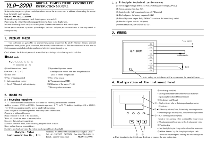
Yatai YLD-2000 User manual

Yatai

Yatai YLD-2000 User manual

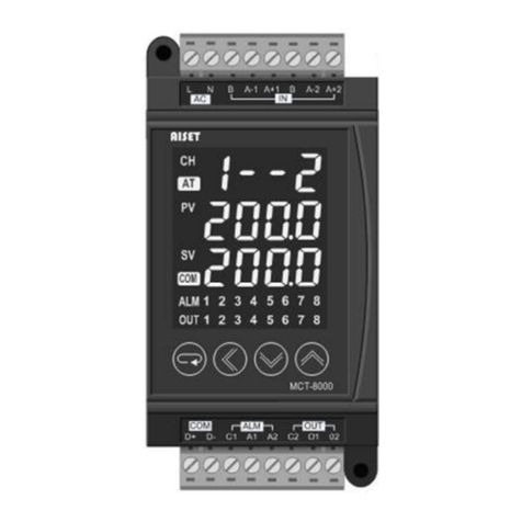
Yatai XMTN-800 Series User manual

Yatai

Yatai XMTN-800 Series User manual

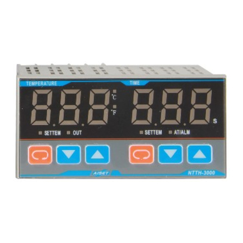
Yatai AISET NTTF/H-3000 User manual

Yatai

Yatai AISET NTTF/H-3000 User manual

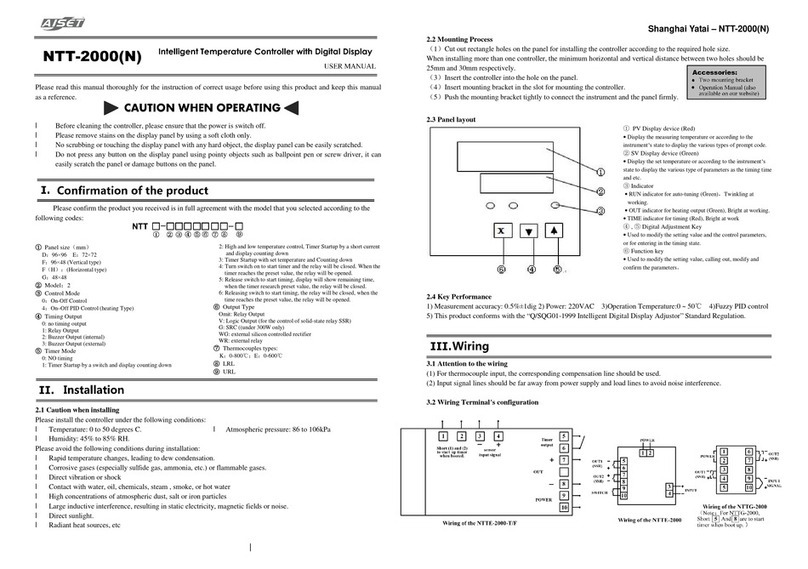
Yatai NTT-2000 User manual

Yatai

Yatai NTT-2000 User manual

Popular Temperature Controllers manuals by other brands

Omron E5CD-B manual

Omron

Omron E5CD-B manual

Ascon tecnologic e33B operating instructions

Ascon tecnologic

Ascon tecnologic e33B operating instructions

Eurotherm 2216L Installing and operating instructions

Eurotherm

Eurotherm 2216L Installing and operating instructions

Thermal Care Oiltherm RO Operation, installation, and maintenance manual

Thermal Care

Thermal Care Oiltherm RO Operation, installation, and maintenance manual

iNels RFTC-10/G manual

iNels

iNels RFTC-10/G manual

dixell WING XW60VS Installation and operating instructions

dixell

dixell WING XW60VS Installation and operating instructions

TPS WP-84 manual

TPS

TPS WP-84 manual

Omron EJ1G datasheet

Omron

Omron EJ1G datasheet

CEM AI-321 user manual

CEM

CEM AI-321 user manual

MULTISPAN TC-49 operating manual

MULTISPAN

MULTISPAN TC-49 operating manual

Warner KilnTroller II quick guide

Warner

Warner KilnTroller II quick guide

Siemens RLE132 manual

Siemens

Siemens RLE132 manual

Airwell MS 1040 F manual

Airwell

Airwell MS 1040 F manual

Ranco ETC installation instructions

Ranco

Ranco ETC installation instructions

Omron E5GN instruction manual

Omron

Omron E5GN instruction manual

Love Controls C Series instruction sheet

Love Controls

Love Controls C Series instruction sheet

wtw SensoLyt 700 SW operating manual

wtw

wtw SensoLyt 700 SW operating manual

Uni-Ubi Uface 5-Temp Product Booklet

Uni-Ubi

Uni-Ubi Uface 5-Temp Product Booklet

manuals.online logo
manuals.online logoBrands
  • About & Mission
  • Contact us
  • Privacy Policy
  • Terms and Conditions

Copyright 2025 Manuals.Online. All Rights Reserved.