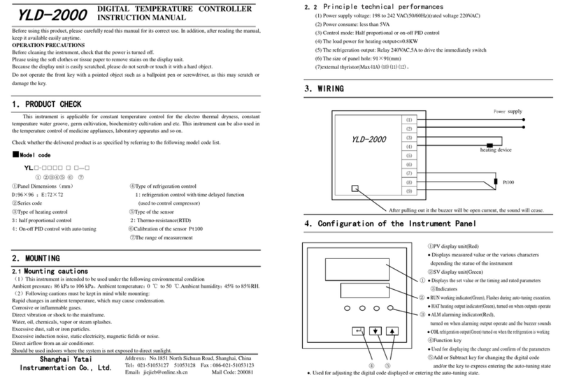
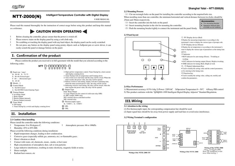
Yatai XMTN-800 Series User manual

XMTN-800 seriesMulti-channelIndependentAuto
tuningPID TemperatureController Operation Manual
1.Wiringwarning
Ifthecontrollerfailsoranerroroccurs, thesystemmayfail and anexternalprotectioncircuitis
installedtopreventsuchanaccident.
Topreventthecontrollerfromdamage orfailure, use properfuse toprotectthepowercordand
input/outputlinefromcurrentshock.
2. Powersupplyofcontroller
Topreventelectricshockorcontrollerfailure, please checktheconnection afterall connectionwork
iscompleted.
3. Use nearflammablegasisprohibited
Inordertopreventfire, explosion orcontrollerdamage, it isprohibitedtouse inplaces where
inflammable, explosivegas orsteamisdischarged.
4. Donottouchtheinsideofthecontroller
Donottouchtheinsideofthecontrollertopreventelectricshockorburning. Ifit occursanyquality
problem, please contactShanghaiyataiinstrumentCo., LTD. Onlytheservice engineerofyataican
checktheinternalcircuitorchangeparts.Thecontrollerhas highvoltageand hightemperature
componentsinside, itisverydangeroustotouchit withoutpermission!
5. Itisstrictlyforbiddentochangetheinstrument
Inordertopreventaccidentsorcontrollerfailure, it isstrictlyforbiddentochangethecontroller.
6.Maintain
Inordertopreventelectricshock,thecontrollerisuseless orinvalid. OnlyYataiservice engineercan
replace theparts.Thecontrollershouldbemaintainedregularlytoensurelong-termsafeoperation.
Somepartsinsidethecontrollermaybedamagedwiththeextension oftime.
7. Clean
Wipethecontrollerafterpoweroff. Toremovestainsfromthedisplay, use asoftclothorcottonpaper.
Thedisplayispronetoscratches. Don'trubortouchwithhardobjects. Donotuse screwdriverorpen
orotherhardobjectstooperatethebutton, otherwise it will damageorscratchthebutton.
1. Productconfirmation
1.1. Please refertothefollowingselectioncodetoconfirmwhethertheproductdeliveredis
completelyconsistentwiththemodelyouselected
1.2. Listofcommon inputtypes and Temperatureranges
No. Inputtype SN Graduation
Maximumrangeofmeasurement
DegreesCelsius )Fahrenheit ℉)
1 thermocouple 1 E -270 1000 -454 1832
2 thermocouple 2 J -210 1200 -346 2192
3 thermocouple 3 K -270 1372 -454 2501
4 thermocouple 4 N -270 1300 -454 2372
5 RTD 15 Pt100 -200 0850 -328 1562
6 Other sensors Customized -500 4000
1.3. Maintechnicalindicators
1)measurementaccuracy:+0.5%FS +1db;Cyclecontrolcycle:0.2second/every8loops.
2)powersupply:24VDC +/-10%Alsocancustomize 100 ~240VACpowersupplyform.
3)operatingenvironment: atmosphericpressure:86~106kPa;10 ~50ambienttemperature:
-Relativehumidity:45 ~85%RH.
4)avoid:
Condensationthatcanbecausedbyasharpchangeinambienttemperature.
Directvibration orimpactofthemainstructure.
Water, oil, chemicals, smokeorsteampollution. Corrosiveand flammablegases.
Too muchdust,salt,ormetalpowder.
2. Appearance and installation
2.1. Controllerappearance
Themaximumheightofthecontroller(includingtheterminal) is112mm;
Thewidthofthecontrolleris56mm, 76mmand 116mm.
Thedepthofthecontrolleris78mm.

2.2. Controllerinstallation
M3screwinstallation,mountingholeis102mmX(width-10mm)rectangulardiagonalpoint.
DIN46277rail (35mmwide)rail mounting.Removethecontrollerbypullingdownthe
assemblyhookoftheguiderail。
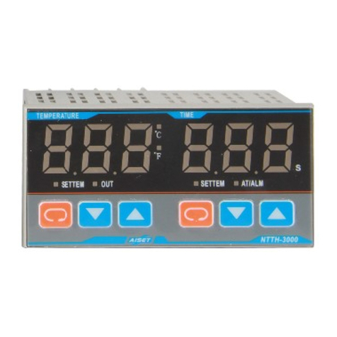
2.3. Displayand operationpanel
3. Terminalblocks
3.1. Wiringdiagramofupperterminal
3.2. Wiringdiagramoflowerterminal

4. Controlparameter setting
4.1. Bootinformation
full screen>>> XMTN(Nshowsthequantityofzones)>>>V3.00(Softwareversion
number)>>> normalcondition
4.2. CHANNELSELECT
Afterlongpress orforonesecond,thecurrentloopnumberstartsflashing,and then
shortpress ortoswitchthecontrolloop.TheN+1channelisthetemperaturedisplay
oftheenvironment(coldendofthermocouple).
4.3. Controlparametersetting
Longpress for3secondstoenterthesettingstateofcontrolparameters.Atthistime,
theupperrowdisplaysparameterpromptSV,andthelowerrowdisplayscontrolparameters.
Atthispoint,thesingledigit flashes,shortpress andmovetheflshingdigits.After
selectingthenumberofdigitstobemodified,short press ortomodifythecontrol
parameter.Continuetopress ,and displayeachparameterpromptintheupperrow.After
findingtheparameterthatneedstobemodified,continuetopress tomovetheflshing
digits.Afterselectingthenumberthatneedstobemodified,press oragaintomodify
thecontrolparameter.
Longpress formorethan1second,thecontrollerautomaticallyreturnstothenormal
controlstate(no buttonoperation within60seconds,thecontrollerautomaticallyreturnstothe
normalcontrolstate).
4.4. AlistofcontrolparameterSettings
No.
Parameter
Name Symbol
DataRange
Unit
Introductions
Initial
value
1 Setvalue
SVL SVH
Thesettargetvalueofthezoneofthecontroller 100
2 Thelower
limitalarm 1
AL1 -500 4000
See 4.5,alarmoutputinstructionsfordetails 50
3 Thelower
limitalarm 2
AL2 -500 4000
SameasAL1,butcanonlybeoutput through
communication 50
4 Upper limit
alarm 1 AH1
-500 4000
See 4.5,alarmoutputinstructionsfordetails 50
5 Upper limit
alarm 2 AH2
-500 4000
SameasAH1,butcanonlybeoutput through
communication 50
6 Alarm type
SA 00 66
Thesingledigit ofXX istype1ofalarm,whilethe
tendigitistype2ofalarm.X=0:noalarm;1:upper
limitdeviationalarm;2:lower limit deviationalarm;
3:alarmoutsidethedeviation valueofupperand
lower limits;4:alarmwithin thedeviation valueof
upper andlower limits;5:upper absolutevalue
alarm;
01
7
Positiveand
negative
action control
andfirst
power on
alarm enable
EA 000 111
ThehundreddigitsofXXX are positiveand
negativecontrol options:X=0:reactioncontrol
(heatingtype);1:positiveactioncontrol (cooling
type).ThetendigitofXXX is firstchoice ofalarm
2,thesingledigitofXXX isfirst choiceofalarm 1:
X=0:Afterthepoweron thealarmconditiondoes
notalarm,thenall alarm ifthealarmconditionis
met;1:all alarmifthealarm condition ismet.
011
8 Proportional
band P 09999
Regulationofproportionalaction:thelarger theP,
thesmaller theproportionalaction,thelowerthe
systemgain.0:changetoon-off control mode.At
thispoint,theintegraltimeIbecomes0.1timesof
theupper limitoftheinsensitiveregion andthe
differentialtimeDbecomes0.1timesofthelower
limitoftheinsensitiveregion.
30
9Integraltime
I 09999 Sec.
Integralactiontimeconstant:thelarger theI,the
weaker theintegralaction,mainlyusedtoeliminate
thestaticdifference.0:becomeaPDcontrol
method,theintegralinhibitArtoset(RESET),and
theArissettozero,theunitfor,isusedto
eliminatestaticerror.WhenP=0,see thedescription
ofP.
240
10
Differential
Time d 09999 Sec.
Differentialactiontimeconstant:thelarger theD,
thestrongerthedifferentialaction,whichis mainly
usedtorestrain theovershootofmeasuredvalues.
WhenP=0,see thedescription ofP.
60
11
Restrained
Integration
Ar 0100 %
RestrainedIntegrationratio: thelargertheAr,the
larger theoverthrust,andthesmallertheAr,the
possiblestaticdifference.
Whentheintegraltime Iisequalto0,see the
description oftheintegraltimeI
100
12
Control cycle
t 1100 Sec.
Outputofthyristororsolid-staterelay:2~3seconds;
Relayoutput:20~30seconds 3
13
Sensorerror
correction Pb -500 4000
Usedtocorrectmeasurementerrorcausedbysensor
andthermocouplecompensationwire 0.0
14
Autotuning
At nOorYES
YES:startself-tuningandrestorenOafter
self-tuning.If theself-tuningruleisnotcompleted
within4hours,theoriginalP,IandDvaluesarestill
usedforcontrol. nO
15
Autotuning
Limit AtU 0100 %
Inordertoovercometheovershootphenomenon of
theAutotuningtime,theAutotuningcontrol point
canbeloweredtoSVxATU. 100
16
Graduation
Sn018
See 1.2listofcommonlyusedinputtypesandrange
fordetails. 3-K
17
Decimal
point dP 01
0:theresolution ofthemeasuredvaluesPV1 ;
1:theresolution ofthemeasuredvaluesPV0.1
0
18
Filter
coefficients
FILt 0250
Thesmaller this value,thefasterthemeasuredvalue
responds,but theremaybefluctuations; Thelarger
thisvalue,theslower themeasuredvalueresponse
andthemore stablethedisplay.
125
19
Screen
blanking dt 0250
Usedtosuppress thechangesensitivityofthe
displayvalue,andtherangeofinhibition is 0.1
timesofthedisplayinhibitiondt. 15
20
Alarm1
differential
gap FH1 -500 4000
Thedifferentialgapis0.1timesofFH1 4
21
Upper limit
-500 4000
ThehighestmeasuredvalueisSVH 300

ofmeasured
value
22
Lower limit
of
measurement
-500 4000
ThelowestmeasuredvalueisSVL.
Thisparameter shouldbelowerediftheambient
temperatureistoo low 0
23
Control the
outputswitch
SSt 01
0:control outputoff(SVdisplays0FF undernormal
state),andonlytheoutputisoff,otherssuchas
alarm normalwork;1:outputopen. 1
24
Alarm2
differential
gap FH2 -500 4000
Thedifferentialgapis0.1timesofFH2 4
25
Temperature
oftheunit
switch Ctr 01
0:;
1:℉。0
26
Overshoot
restrain Ar2 0250
Reserved,not usednow 0
Note:ifyou didnotpress formorethan1second aftermodifyingtheparameter,theindividual
parametersmaynotbesaved.
Thechangeofeachparameterinthelistmaychangethecontroleffect. Please becareful!
4.5. AutotuningPIDparameterfunction
Follow4.4.Controlparametersettingoperationtofindtheautotuningstart parameterAT,
and displaythe “AT”promptontheupperrow,and “nO”promptonthelowerrow,indicating
thatcurrentlyNolimit settingorautotuningfunctionhas beenopened, Clicktodisplaythe
“YES”promptbelow,indicatingthattheuserisreadytostart theloopautotuningfunction;If
thetemperatureintheloopsystemisnotallowedtoexceedthesetvalueSVtoomuch, thenext
parametercanbesetas autotuninglimit ATU,whichcanbesetas between70 and80%(Auto
tuningiscarriedouton 70 ~80% ofthesetvalue),Then
press morethan1secondtoexit parametersSettings,
ATthispointtheATindicatorwill flicker,indicatethatthe
controllerintheprocess ofautotuning,temperature
fluctuationsaftertwotothree timestocompletethewhole
process ofautotuning,thentheATindicatorlightoff,it is
concludedthatasetofsuitablefortheloop controlofP,I,
Dparametervalues,and accordingtothenewP,I,D
parameterscontrol, thisP, I, Dparameterswill beforeverinthecontroller.
Iftheautotuningprocess needstobeinterruptedduringthesettingprocess,thecontrol
parametermenu needstobere-entered,Settheautotuningstart parameterATtonO,andthen
exit thecontrolparametermenu.ATthistime,theATindicatorisoff,andthecontrollerwill
controlaccordingtotheoriginalP, I,Dparameters.
4.6. Alarmoutputinstruction
No. Type Actioncondition Schematicdiagram (forexample,
alarm1only)
Alarm1 Alarm2
1 alarm free Single-digitofSA=0。
tensdigitofSA=0。
2 Upper limit
deviation
alarm
Single-digitofSA=1;
PV>SV+AH1 Alarm;
PV≤SV+AH1-FH1
removealarm
tensdigitofSA=1;
PV>SV+AH2 Alarm;
PV≤SV+AH2-FH2
removealarm
3 Minimum
deviation
alarm
Single-digitofSA=2;
PV<SV-AL1Alarm;
PV≥SV-AL1+FH1
removealarm
tensdigitofSA=2;
PV<SV-AL2Alarm;
PV≥SV-AL2+FH2
removealarm
4
Upper and
lower limit
deviation
outsidealarm
Single-digitofSA=3;
PV>SV+AH1 Alarm;
PV≤SV+AH1-FH1
removealarm;
PV<SV-AL1Alarm;
PV≥SV-AL1+FH1
removealarm
tensdigitofSA=3;
PV>SV+AH2 Alarm;
PV≤SV+AH2-FH2
removealarm;
PV<SV-AL2Alarm;
PV≥SV-AL2+FH2
removealarm
5
Upper and
lower limit
deviation
withinalarm
Single-digitofSA=4;
SV-AL1<PV<SV+AH
1Alarm;
PV≥SV+AH1+FH1or
PV≤SV-AL1-FH1
removealarm
tensdigitofSA=4;
SV-AL2<PV<SV+AH
2Alarm;
PV≥SV+AH2+FH2or
PV≤SV-AL2-FH2
removealarm
6 Upper
absolute
valuealarm
Single-digitofSA=5;
PV>AH1 Alarm;
PV≤AH1-FH1remove
alarm
tensdigitofSA=5;
PV>AH2 Alarm;
PV≤AH2-FH2remove
alarm
PV
Alarm
Output
AH1
FH1
Alarm
Remove
7 Lower limit
absolute
valuealarm
Single-digitofSA=6;
PV<AL1Alarm;
PV≥AL1+FH1remove
alarm
tensdigitofSA=6;
PV<AL2Alarm;
PV≥AL2+FH2remove
alarm

4.7. Errormessage
WhenthemeasuredvaluePVislowerthanSVL,itisshownas (communication
outputis-16666),indicatingthatthethermocoupleisinverselyconnected,thermalresistance
short-circuitorthree-wireconnection iswrong,andtheambienttemperature(coldend
temperature)istoo low.Please checkwhetherthesensorwiringiscorrectorthesensoris
damaged.Whentheambienttemperatureistoolow, thelowerlimitSVLcanbeloweredtotest.
WhenthemeasuredvaluePVishigherthanSVH,it isshownas (communication
outputis18888),whichindicates thatthethermocoupleisopencircuit orthethermalresistance
isopencircuit,andtheactualmeasurementtemperatureishigherthantheupperlimit ofthe
range(thesensorand theheatingunit do notformthesame loop, resultinginlong-termheating).
Please checkwhetherthesensorisdamagedand thecontrolloopisconnectedcorrectly
5. Communication connection and set-up
5.1. Multiplecontrollercommunicationconnection
WhenthesensorindexingcodeSnisnotsettoavalidvalue,it isdisplayedas Erro
(communication outputis15555).
5.2. Communicationparametersetting(Innormalstate,longpress formorethan3seconds
toenterthecommunicationparametersetting)
No
ParameterName
Symbol
DataRange
Introductions Initial
value
1
Communication
address Addr 0254
Commonaddressesare 0~9and canbeextendedto
254;
Including:
0isbroadcastaddress;
251 is theinitialvalueaddress ofall parametersrestored
atfactory:
WhenAddr=251,press andall parametersofthe
controller are restoredtothefactoryinitialvalue.About 5
secondslater, thesystem will restartand enter thenormal
workingstateautomatically.
1
2
Communication
rate
(bps)bAUd
The
valueof
010
0:600;1:1200;2:2400;3:4800;
4:9600;5:14400;6:19200;7:28800;8:38400;
9:57600;10:115200。9600
3
Thenumberof
Measurement
andautomatic
inspection
function
CHLS
01 88
0X:Thesingledigitisusedtolimit thecontrol loop
number,ThesetrangeofXis 1 8(matchwith
hardware)。
X0:10digitsformanual/automaticinspectionfunction
setting;
X=0:Manuallyswitchthelooptobedisplayed;
X=1 8:Show stoptime foreachchannelduring
automaticinspection, unitissecond.
28
6. Maintenance and preservation
6.1. Maintenance:within18monthsfollowingthepurchase oftheinstrument,thefactoryshall be
responsiblefortheoverall warrantyforthefailureofmanufacturingquality.Iftheinstrumentis
damagedduetoimproperuse,thefactorywill chargeusersrepaircost,andtheinstrumenthas
lifetimewarranty.
6.2. Storage:theinstrumentshouldbekeptindry, ventilatedand free ofcorrosivegas withcomplete
package.
海亚泰仪表有限公司
Shanghaiyataiinstrumentco., LTD
Phone:021-66186368;021-66186369
Fax :021-66186226technologyconsulting :
021-36160962
E-mail:yatai@yatai.sh.cn http://www.yatai.sh.cn
Address:no.128, zhenyuanroad,baoshancity
industrialpark, Shanghai
Documentnumber:YT01 201703032.0
oooo
oooo
Table of contents
Other Yatai Temperature Controllers manuals
Popular Temperature Controllers manuals by other brands

Homematic IP
Homematic IP HmIP-SK1 operating manual

Thermal Care
Thermal Care RA Series Installation & operation manual

EMKO
EMKO ESM-3710-N instruction manual

Excelair
Excelair Dual Room Damper Package Installation

Thermo Technologies
Thermo Technologies USDT 2004 Installation and user guide

wtw
wtw SensoLyt 700 SW operating manual

Resol
Resol DeltaSol AX Installation, operation, functions and options, troubleshooting

Johnson Controls
Johnson Controls TE-6800 Series installation instructions

PPI
PPI LabCon user manual

Powell
Powell BriteSpot Fiber-Opc quick start guide

Kingspan
Kingspan SC100 Installation and operating instructions

Siemens
Siemens RAV12 series user manual