manuals.online logo
Brands
  1. Home
  2. •
  3. Brands
  4. •
  5. YOKOGAWA
  6. •
  7. Accessories
  8. •
  9. YOKOGAWA CT1000A User manual

YOKOGAWA CT1000A User manual

User's
Manual
The following symbols are used in this manual.
This symbol is used in conjunction with the word “WARNING” or “CAUTION.”
Ce symbole est accompagné des termes “AVERTISSEMENT” et “ATTENTION.”
WARNING Calls attention to actions or conditions that could cause serious or fatal injury to
the user, and precautions that can be taken to prevent such occurrences.
AVERTISSEME
NT Attire l’attention sur des gestes ou des conditions susceptibles de provoquer
des blessures graves (voire mortelles), et sur les précautions de sécurité
pouvant prévenir de tels accidents.
CAUTION Calls attention to actions or conditions that could cause light injury to the user or
damage to the instrument or the user’s data, and precautions that can be taken
to prevent such occurrences.
ATTENTION Attire l’attention sur des gestes ou des conditions susceptibles de provoquer des
blessures légères ou d’endommager l’instrument ou les données de l’utilisateur,
et sur les précautions de sécurité susceptibles de prévenir de tels accidents.
Note Calls attention to information that is important for proper operation of the instrument.
Safety Precautions
This product is designed to be used by a person with specialized knowledge.
Make sure to observe the following safety precautions when handling the current sensor.
If the instrument is used in a manner not specified in this manual, the protection provided by the
instrument may be impaired. YOKOGAWA assumes no liability for the customer’s failure to comply with
these safety precautions. Before you use the current sensor, read the measuring instrument’s manual
to fully acquaint yourself with its specifications and handling.
This manual is an essential part of the product; keep it in a safe place for future reference.
The following symbols are used on this instrument. Les symboles suivants ont été placés sur l’instrument
Handle with care. Refer to the user’s manual
or service manual. This symbol appears on
dangerous locations on the instrument which
require special instructions for proper handling
or use. The same symbol appears in the
corresponding place in the manual to identify
those instructions.
À manipuler délicatement. Toujours se reporter aux
manuels d’utilisation et d’entretien. Ce symbole a
été apposé aux endroits dangereux de l’instrument
pour lesquels des consignes spéciales d’utilisation ou
de manipulation ont été émises. Le même symbole
apparaît à l’endroit correspondant du manuel pour
identifier les consignes qui s’y rapportent.
Risk of electric shock Risque de choc électrique
Hot surface Surface trés chaude
Make sure to observe the following safety precautions to prevent electric shock, personal
injury, or damage to the instrument.
WARNING
• Use the Instrument Only for Its Intended Purpose
This instrument is a current output type current sensor with a 1500:1 current transformation
ratio that performs transformation on the primary current.
Use the instrument only for measuring current.
• Beware of electric shock.
• Do not perform measurement if the case is damaged.
• Do not operate the instrument with wet hands, in a rainy or humid environment, or if any
water droplets are visible on it.
• Condensation may appear if sudden changes in temperature occur. If this happens,
let the instrument acclimatize to the new temperatures for at least one hour, then refrain
from using the instrument until confirming that there is no condensation.
• Do not disassemble the instrument.
The instrument should be disassembled by qualified personnel only.
• Use the correct power supply.
Ensure that the source voltage matches the voltage of the power supply before turning the power ON.
• Do not use uninsulated measurement conductors or cables.
Use conductors or cables with reinforced insulation.
• Make sure that the surface temperature of measurement conductors is within the
instrument's operating temperature range.
• Although it is well-insulated, do not touch the instrument or secondary output cable while
voltage is being applied to the primary conductor.
• Connect the secondary signal output before supplying power to the instrument.
• Do not disconnect the secondary output while power is being supplied to the instrument to
prevent electric shock or damage to the instrument.
• Do not apply primary current before supplying power to the instrument to prevent electric
shock or damage to the instrument.
• Do not input excessive current as malfunction or damage may result.
• Do not allow vibrations to disturb the instrument after it has been set in place as damage
may result.
French
AVERTISSEMENT
• Utiliser l’instrument aux seules fins pour lesquelles il est prévu
Cet instrument est un capteur de courant du type de débit de courant.
Utiliser l’instrument uniquement pour mesurer le courant.
• Faire attention aux chocs électriques.
• Ne pas effectuer une mesure si le boîtier est endommagé.
• Ne pas faire fonctionner le dispositif avec les mains humides, dans un environnement
pluvieux ou humide, ou si des gouttelettes d’eau sont visibles dessus.
• La condensation peut s’effectuer et les changements brusques de température se
produisent. Si cela se produit, laisser le dispositif s’acclimater aux nouvelles températures
pendant au moins une heure, puis éviter de l’utiliser jusqu’à confirmer qu’il n’y a pas de
condensation.
• Ne pas démonter le dispositif.
Le dispositif doit être démonté uniquement par un personnel qualifié.
Thank you for purchasing the AC/DC Current Sensor. To ensure correct use, please read this manual
thoroughly before beginning operation.
Please familiarize yourself with the functions and characteristics of the AC/DC current sensor prior to
operation. After reading this manual, keep it in a safe place.
IM CT1000A-01EN
1st Edition
IM CT1000A-01EN 1/2
• Vérifier l’alimentation.
S’assurer que la source de tension correspond à la tension de l’alimentation avant la mise
sous tension.
• Ne pas utiliser de conducteurs ou de câbles de mesure non isolés.
Utiliser des conducteurs ou des câbles avec isolation renforcée.
• S’assurer que la température de surface des conducteurs de mesure se situe dans la plage
de température de fonctionnement du dispositif.
• Bien qu’il soit bien isolé, ne pas toucher le dispositif ou le câble de sortie secondaire pendant
que la tension s’applique au conducteur primaire.
• Connecter la sortie du signal secondaire avant d’alimenter le dispositif.
• Ne pas débrancher la sortie secondaire lorsque l’alimentation électrique est fournie au
dispositif afin d’éviter tout risque de choc électrique ou d’endommagement de l’instrument.
• Ne pas appliquer de courant primaire avant d’alimenter le dispositif afin d’éviter tout risque
d’électrocution ou d’endommager l’instrument.
•
Ne pas entrer de courant excessif, car un dysfonctionnement ou des dommages peuvent en résulter.
• Ne pas laisser les vibrations perturber le dispositif après qu’il a été mis en place, car des
dommages peuvent en résulter.
1. Description
This instrument is a current output type current sensor with a 1500:1 current transformation ratio
that performs transformation on the primary current. After familiarizing yourself with the performance
and functions of this instrument, you will be able to use it in conjunction with measuring instruments
from YOKOGAWA.
2. Checking the Contents of the Package
The current sensor consists of the following parts.
CT1000A
Model
Serial Number
MODEL Specifications
CT1000A Current transformation ratio is 1500:1
S/N 0000000000
Standard Accessories
The instrument is shipped with the following accessories.
Make sure that all accessories are present and undamaged.
Manual No. Manual Title Description
IM CT1000A-01EN CT1000A
AC/DC Current Sensor
User’s Manual
This manual. This manual explains the
handling precautions, basic usage, and
specifications of this instrument.
IM CT1000A-01JA CT1000A
AC/DC Current Sensor
The Japanese version of the above manual
IM CT1000A-92Z1 CT1000A
AC/DC Current Sensor
Document for China
The “EN” and “JA” in the manual numbers are the language code.
Contact information of Yokogawa offices worldwide is provided on the following sheet.
PIM 113-01Z2 Inquiries List of worldwide contacts
Accessory (Sold Separately)
The optional accessory below is available for purchase separately. Use the accessory specified in
this manual. Moreover, use the accessory of this product only with Yokogawa products that specify
it as accessory.
Output connector B8200JQ
Accessory (sold separately) is not covered by warranty of this instrument.
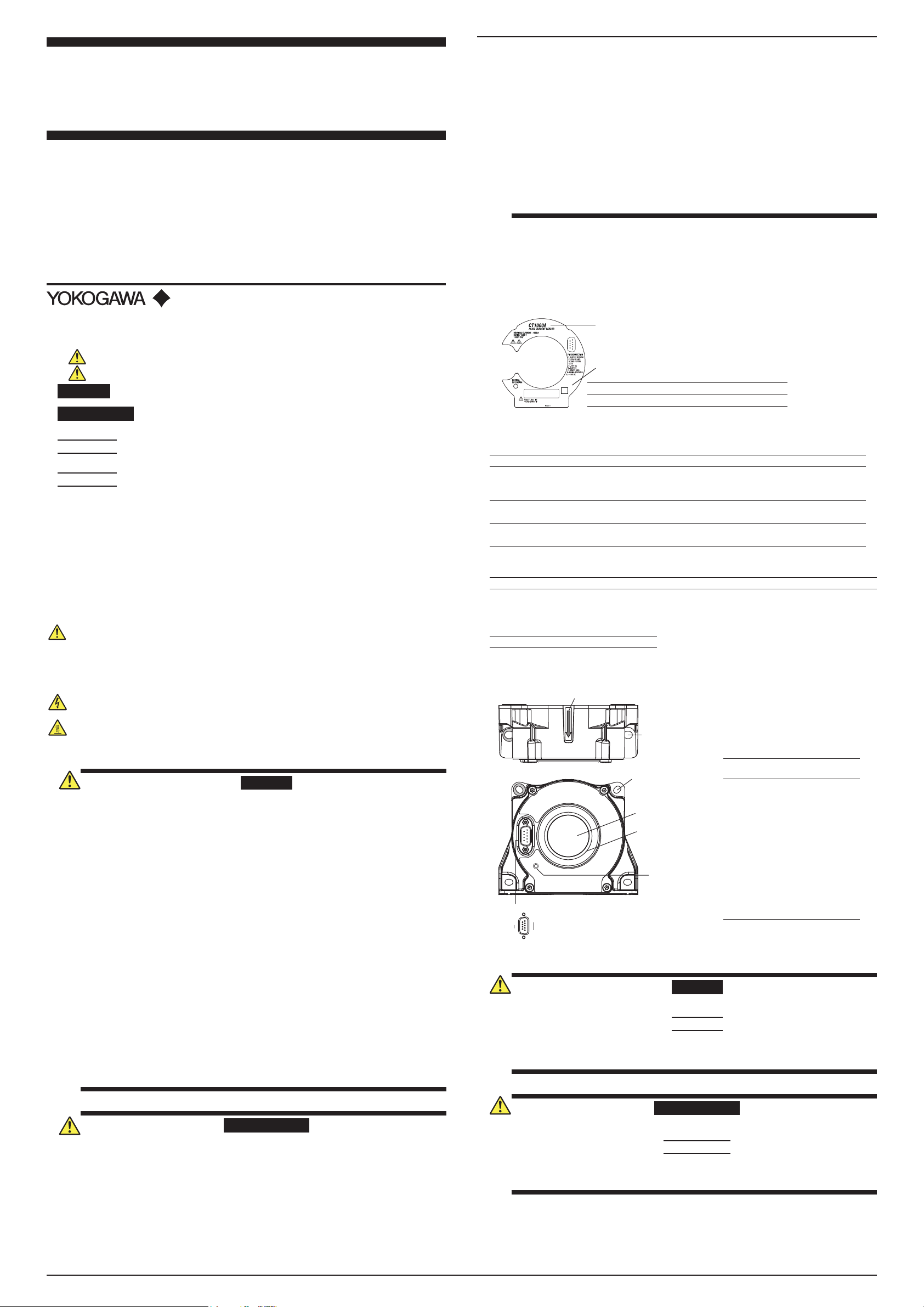
3. Part Names
Signal allocation of secondary
connector (PIN CONNECTION)
Pin
No.
Signal (Remarks)
1. OUTPUT RETURN
2. (DON’T USE)
3. GND STATUS
4. 0 V
(Power Supply Input)
5. -15 V DC
(Power Supply Input)
6. OUTPUT
(Secondary Signal)
7. (DON’T USE)
8. NORMAL OP STATUS
(Normal Operation Status)
9. +15 V DC
(Power Supply Input)
Figure 1. Names of Parts and Pin Assignments
Attachment screw
slotted holes
(two: for M6)
Front
Top
1
5
6
9
Pin assignment
Direction of current
Secondary connector
Operation status
LED
Primary conductor
feed-through hole
Conductor guide
Attachment screw
slotted holes
(four: for M5)
4. Operating Procedure
WARNING
Do not apply primary current before supplying power to the instrument to prevent electric
shock or damage to the instrument.
CAUTION
Ensure that the current flowing to the primary conductor of the object to be measured is
within the measuring range (current rating).
If the current exceeds the measuring range, the instrument may overheat and get damaged.
French
AVERTISSEMENT
Ne pas appliquer de courant primaire avant d’alimenter le dispositif afin d’éviter tout risque
d’électrocution ou d’endommager l’instrument.
ATTENTION
S’assurer que le courant qui s’achemine vers le conducteur primaire de l’objet à mesurer se
situe dans la plage de mesure (courant nominal). Si le courant dépasse la plage de mesure,
le dispositif peut surchauffer et subir des dommages.
1.
Connect the secondary connector on the instrument to the current input terminal on the
measuring instrument, and connect to 0 V (common) and ±15 V on the power supply.
2.
Set up the measuring instrument and power supply to match the specifications of the current
transducer. Carefully read the user’s manuals for your measuring instrument and power supply
to perform the correct procedure for making the connections.
CT1000A
AC/DC Current Sensor
1st Edition: July 2019 (YMI)
All Rights Reserved, Copyright © 2019, Yokogawa Test & Measurement Corporation
Printed in Japan
Secondary connector
of the current sensor
4
5
9
6
Power supply
0 V (common)
–15 V
+15 V
Current input
terminal
Measuring instrument
Figure 2. Connection Example
1* Make sure that the total load
resistance including measuring
instrument's internal resistance and
wiring resistance is within the
specification.
±
3.
Insert the primary conductor into the primary conductor feed-through hole on the instrument.
Make sure that the direction of current flow matches the arrow on the instrument.
Correct
Pass only
a single conductor
Primary
Conductor
Secondary
connector
Incorrect
Using an magnetic
-shielded conductor
Using two parallel
conductors
Current flows in
both directions
Direction
of current
Figure 3. Insertion of a Conductor
4.
Check that power is being supplied to the instrument, and then apply the primary current.
5.
Read the measured values. The following calculation is used to determine the current flowing
through the primary conductor.
Example: When the output current from the instrument's secondary connector (pin 6) is 100 mA.
CT1000A: 100 mA x 1500 = 150 A
Note
• If the operation status LED is off even when power is being supplied to the instrument,
the protection function may be activated. Immediately stop the primary current.
• Pass only the conductor in which the current you want to measure is flowing through
the primary conductor feed-through hole.
Correct measurements cannot be taken if you pass a conductor with magnetic shielding or
conductors in which the currents are flowing in opposite directions through the feed-through
hole. (See the examples in Figure 3.)
• Make sure the primary wiring and secondary wiring do not interfere with each other.
The secondary wiring may be affected by the primary wiring because it uses a very small current.
Make the secondary wiring as short as possible and maintain its distance from the primary
wiring, without allowing them to be parallel to each other. We recommend AWG24 or higher for
the secondary wiring material. Twisted-pair may be better than shielded cable for measurement
applications such as inverters.
• The instrument outputs current. Connect the instrument to a measuring instrument with
current input. To connect the instrument to a measuring instrument with voltage input, use an
appropriate shunt resistor to connect the instrument to the voltage input terminals.
• Configure your setup so that the load resistance of the measuring instrument connected to the
secondary signal output is within the specification range.
• Correct measurements may not be possible in places where there is an extremely strong
external magnetic field besides the magnetic fields produced by the primary current of the
object to be measured or where there is a strong electric field.
• Do not apply excessive force to the secondary connector to prevent damage to the instrument.
Power Off If Abnormal Behavior Occurs
If you notice smoke or unusual odors coming from the instrument, immediately turn off the
measuring instrument supplying the power. Then, contact your nearest YOKOGAWA dealer.
Status circuit diagram
Active Low Output
Operation status
ICEmax : 30 mA
ICEmin : 2 mA
Collector
DC
Power
Supply
R
3
8
+
-
V+ : 4 ...+24 V
Rmin(kΩ) =
Rmax(kΩ) =
V+(V) - 0.4 V
30 mA
V+(V) - 0.4 V
2 mA
D-Sub
(9 pin)
Emitter
CT1000A
USER SIDE
Photocoupler operation:
ON :
CT1000A is OK
(normal mode)
OFF : CT1000A is not OK
Operation status output
Status
Operation Status (8-pin) Output
Note
Normal Less than 0.7 V (Typical) The LED turns on.
Overloaded V+ The LED turns off. A low frequency signal is output
as a secondary signal output.
Overload Protection
The overload occurs when the primary current (Ip) exceeds a trip level such that the fluxgate
detector becomes completely saturated and, consequently, the current sensor will switch from
normal operation to overload mode.
This trip level (Ipm) is guaranteed to be greater than 1500 Apeak and its actual value depends on
operating conditions such as temperatures and measuring resistance.
During the overload mode, the current sensor generates and outputs a low frequency signal.
The measuring operation resumes when the primary current returns in the measuring range
(1000 Arms).
5. Specifications
Item Specification
Current Rating DC: 0 to 1000 A
AC: 1000 Arms, 1500 Apeak
Output Current Primary rated current at 1000 A is 666.6 mA.
Current Transformation Ratio 1500:1
Direction of Current Per the arrow printed on the main unit.
Accuracy DC: ±(0.04% of reading + 30 μA)
50/60 Hz: ±(0.04% of reading + 30 μA) sine wave
Standard Conditions Temperature: 23 ± 5°C
Voltage to earth: 0 V
Conductor position: center
Conductor: φ25 mm; length,300 mm or more; straight
Accuracy warranty period 12 months
Accuracy-guaranteed temperature
and humidity
-40 to 85°C,
20 to 80%RH (no condensation)
Temperature Coefficient In the -40 to 18°C, 28 to 85°C ranges: ±0.01%/°C or less
Effect of Position of Conductor Add ±(0.01% of reading)
Measurement Band (-3 dB) DC to 300 kHz
Max. Allowable Continuous Input 1500 Apeak
For the maximum allowable continuous current with respect to
frequency, see figure 4.
Instantaneous Max. Allowable Input
5000 Apeak
(0.1 sec. or less, reference value)
Maximum Rated Voltage to Ground
41000 V, CAT III2
Load Resistance 0 to 1Ω (power supply voltage: ±14.25 V, 85°C)
Start-up time 15 s or less
Operating
environment
Temperature -40 to 85°C
Humidity 20 to 80%RH (no condensation)
Altitude 2000 m or less
IM CT1000A-01EN 2/2
Storage
environment
Temperature -40 to 85°C
Humidity 20 to 80% RH (no condensation)
Altitude 3000 m or less
Power Supply Voltage ±(15 V ± 5%)
Maximum Rated Power Consumption
Approx. 30 VA
Current Consumption
(at Power Supply Voltage)
Approx. (120 mA + output current)
External Dimensions Approx. 128 (W) × 106 (H) × 54 (D) mm
(excluding the connector, conductor guide, and protrusions)
Diameter of Primary Current Hole φ38.2 mm
Secondary Connector D-Sub 9 pin
Weight Approx. 1.3 kg
Recommended fastening torque
• Flat mounting
• Straight mounting
M5×4 steel screws 3.7 N•m
M6×2 steel screws 4.4 N•m
Safety standard1Compliant standards
EN 61010-1 1000 V
Measurement Category: CAT III2
Pollution degree 23
Emissions1Compliant standards
EN 61326-1 ClassB, EN 55011 ClassB, Group1
Immunity1Compliant standards
EN 61326-1 Table 2 (for use in industrial locations)
Length of the secondary cable: 30 m or less (indoor wiring)
Measurement error may temporarily occur under immunity
environments.
Environmental standard1Compliant standards
EN 50581 Monitoring and control instruments including
industrial monitoring and control instruments.
1 Applies to products with CE marks. For information on other products, contact your nearest YOKOGAWA dealer.
2 This instrument is measurement category III product. Do not use it for Measurement Categories IV.
Measurement category O applies to measurement of other circuits that are not directly connected to a main power
supply.
Measurement category II applies to electrical equipment that is powered through a fixed installation, such as a
wall outlet wired to a distribution board, and to measurement performed on such wiring.
Measurement category III applies to measurement of facility circuits, such as distribution boards and circuit
breakers.
Measurement category IV applies to measurement of power source circuits, such as entrance cables to buildings
and cable systems, for lowvoltage installations.
3 Pollution Degree applies to the degree of adhesion of a solid, liquid, or gas which deteriorates withstand voltage or
surface resistivity. Pollution degree 2 applies to normal indoor atmospheres (with only non-conductive pollution).
4 The maximum rated voltage to ground is rms for AC voltage and Vdc for DC voltage.
Maximum Allowable Input Current [Arms]
Frequency [Hz]
Figure 4. Derating of Primary Current by Frequency
1000 10000 100000
10010
100
10
1000
+85
°C
+25
°C
4- 5.5×7.5
slotted hole
Unless otherwise specified, tolerances are ±3%
(however, tolerances are ±0.3 mm when below 10 mm).
Figure 5. External Dimensions
Unit: mm
2- 6.5×8.5
slotted hole
128
109
3.5
(2)
106
54
85
38.2
54
50.5
49
109
28
(2)
1
90
104
6. Malfunction and Servicing
Malfunction
If you experience a breakdown in the instrument due to faulty manufacturing or accidents during
shipping, contact your nearest YOKOGAWA dealer.
Servicing
If you encounter any problems during use, or if the instrument does not appear to be operating
normally, contact your nearest YOKOGAWA dealer.
7. Regulations and Sales in Each Country or Region
Waste Electrical and Electronic Equipment (WEEE), Directive
(This directive is valid only in the EU.)
This product complies with the WEEE directive marking requirement. This marking
indicates that you must not discard this electrical/electronic product in domestic
household waste.
Product Category
With reference to the equipment types in the WEEE directive, this product is classified
as a “Monitoring and control instruments” product.
When disposing products in the EU, contact your local Yokogawa Europe B.V. office.
Do not dispose in domestic household waste.
Authorized Representative in the EEA
Yokogawa Europe B.V. is the authorized representative of Yokogawa Test & Measurement
Corporation for this product in the EEA. To contact Yokogawa Europe B.V., see the separate list of
worldwide contacts, PIM 113-01Z2.
Disposing the Product
When disposing of YOKOGWA products, follow the laws and ordinances of the country or region
where the product will be disposed of.

Other YOKOGAWA Accessories manuals

YOKOGAWA FU20F User manual

YOKOGAWA

YOKOGAWA FU20F User manual

YOKOGAWA SC4AJ Series User manual

YOKOGAWA

YOKOGAWA SC4AJ Series User manual

YOKOGAWA CT60 User manual

YOKOGAWA

YOKOGAWA CT60 User manual

YOKOGAWA FD30 User manual

YOKOGAWA

YOKOGAWA FD30 User manual

YOKOGAWA FU20 User manual

YOKOGAWA

YOKOGAWA FU20 User manual

YOKOGAWA Sushi Sensor Manual

YOKOGAWA

YOKOGAWA Sushi Sensor Manual

YOKOGAWA ISC40G(S) User manual

YOKOGAWA

YOKOGAWA ISC40G(S) User manual

YOKOGAWA SC25V User manual

YOKOGAWA

YOKOGAWA SC25V User manual

YOKOGAWA SC41 User manual

YOKOGAWA

YOKOGAWA SC41 User manual

YOKOGAWA DO72 User manual

YOKOGAWA

YOKOGAWA DO72 User manual

YOKOGAWA Sushi Sensor XS530 User manual

YOKOGAWA

YOKOGAWA Sushi Sensor XS530 User manual

YOKOGAWA SX42 User manual

YOKOGAWA

YOKOGAWA SX42 User manual

YOKOGAWA CT1000 User manual

YOKOGAWA

YOKOGAWA CT1000 User manual

YOKOGAWA FU24 User manual

YOKOGAWA

YOKOGAWA FU24 User manual

YOKOGAWA OR8EFG User manual

YOKOGAWA

YOKOGAWA OR8EFG User manual

YOKOGAWA PH8ERP User manual

YOKOGAWA

YOKOGAWA PH8ERP User manual

YOKOGAWA OR8ERG Series User manual

YOKOGAWA

YOKOGAWA OR8ERG Series User manual

YOKOGAWA PBDH0150 User manual

YOKOGAWA

YOKOGAWA PBDH0150 User manual

YOKOGAWA CT1000 User manual

YOKOGAWA

YOKOGAWA CT1000 User manual

YOKOGAWA Sushi Sensor XS770A User manual

YOKOGAWA

YOKOGAWA Sushi Sensor XS770A User manual

YOKOGAWA PH8EFP User manual

YOKOGAWA

YOKOGAWA PH8EFP User manual

YOKOGAWA FU20-MTS User manual

YOKOGAWA

YOKOGAWA FU20-MTS User manual

YOKOGAWA CT2000A User manual

YOKOGAWA

YOKOGAWA CT2000A User manual

YOKOGAWA PH8EHP User manual

YOKOGAWA

YOKOGAWA PH8EHP User manual

Popular Accessories manuals by other brands

Garmin GDL 90 installation manual

Garmin

Garmin GDL 90 installation manual

Diamond Kinetics PitchTracker Baseball user guide

Diamond Kinetics

Diamond Kinetics PitchTracker Baseball user guide

Honeywell RCW110 installation instructions

Honeywell

Honeywell RCW110 installation instructions

ZEPP Tennis 2 user guide

ZEPP

ZEPP Tennis 2 user guide

BIOS LIVING 57064 manual

BIOS LIVING

BIOS LIVING 57064 manual

Michell Instruments HygroSmart I7000XP user manual

Michell Instruments

Michell Instruments HygroSmart I7000XP user manual

Toshiba teli SPS02 instruction manual

Toshiba teli

Toshiba teli SPS02 instruction manual

Newgy Robo-Caddy Assembly instructions

Newgy

Newgy Robo-Caddy Assembly instructions

Rockwell Automation 42JT-C2LAT1-A2 installation instructions

Rockwell Automation

Rockwell Automation 42JT-C2LAT1-A2 installation instructions

Autonics ADS-SE1 manual

Autonics

Autonics ADS-SE1 manual

SAF-HOLLAND Holland ELI RK-10855-L installation instructions

SAF-HOLLAND

SAF-HOLLAND Holland ELI RK-10855-L installation instructions

CALECTRO CPS-24V Installation instruction

CALECTRO

CALECTRO CPS-24V Installation instruction

Carefree SIMPLY SHADE WINDOW AWNING Installation & operation

Carefree

Carefree SIMPLY SHADE WINDOW AWNING Installation & operation

Gibson Robot Interface Pack owner's manual

Gibson

Gibson Robot Interface Pack owner's manual

Philips CPWBS154 Quick start quide

Philips

Philips CPWBS154 Quick start quide

Motorola C370 Series instructions

Motorola

Motorola C370 Series instructions

Audioaccess DBM21 Software Programming and Hardware Connecting Guide

Audioaccess

Audioaccess DBM21 Software Programming and Hardware Connecting Guide

Maxcess CL Series instruction manual

Maxcess

Maxcess CL Series instruction manual

manuals.online logo
manuals.online logoBrands
  • About & Mission
  • Contact us
  • Privacy Policy
  • Terms and Conditions

Copyright 2025 Manuals.Online. All Rights Reserved.