manuals.online logo
Brands
  1. Home
  2. •
  3. Brands
  4. •
  5. YOKOGAWA
  6. •
  7. Controllers
  8. •
  9. YOKOGAWA SMARTDAC+ GX20 User manual

YOKOGAWA SMARTDAC+ GX20 User manual

GX20/GP20 (/CM2 option)
GM10 (/CM2 and /CS2 options)
920MHz Wireless Communication
First Step Guide
Introduction
Thank you for purchasing the SMARTDAC+ Series GX20/
GP20/GM10 (hereafter referred to as the GX or GP or GM).
This manual explains the 920MHz wireless communication
function of the GX and GP and GM.
For configuring the 920 MHz wireless communication and
descriptions not covered in this manual, see the 920 MHz
Wireless Communication User’s Manual (IM 04L51B01-
41EN), provided as an electronic manual.
For details on the features of the GX/GP/GM/GX70SM and
how to use it, read this manual together with the following
user’s manuals.
• Model GX10/GX20/GP10/GP20 Paperless Recorder First
Step Guide (IM 04L51B01-02EN)
• Model GX10/GX20/GP10/GP20 Paperless Recorder
User’s Manual (IM 04L51B01-01EN)
• Data Acquisition System GM First Step Guide
(IM 04L55B01-02EN)
• Data Acquisition System GM User’s Manual
(IM 04L55B01-01EN)
• Model GX70SM Wireless Input Unit First Step Guide
(IM 04L57B01-02EN)
• Model GX70SM Wireless Input Unit User’s Manual
(IM 04L57B01-01EN)
Electronic Manuals and General Specifications
You can download these documents from the following web
page:
http://www.smartdacplus.com/manual/en/
See page 4 in Precaution on the use of SMARTDAC+ (IM
04L51B01-91EN).
Revisions
November 2017 1st Edition June 2018 2nd Edition
Notice
NO RIGHTS OR LICENSES, EXPRESS OR IMPLIED,
ARE GRANTED TO USE THIRD-PARTY DEVICES
IN COMBINATION WITH THESE PRODUCTS IN
A WIRELESS MESH NETWORK, OR TO USE
THIRDPARTY SERVICES TO ACCESS, MONITOR
OR CONTROL THESE PRODUCTS IN A WIRELESS
MESH NETWORK VIA THE INTERNET OR ANOTHER
EXTERNAL WIDE AREA NETWORK.
Patent Marking
Covered by one or more claims of patents: http://sipcollc.
com/patent-list/ and http://intusiq.com/patent-list/.
Notes on 920 MHz Wireless Communication
• 920 MHz wireless communication can be used only in the
US.
• Only US FCC standards and UL standards are supported.
• This product has obtained FCC certification. As such, the
following acts may be punishable by law.
• Disassembling or altering the product
• Removing the certification label
• Using an antenna other than the specified option
• Communication may not be possible in the following
locations due to radio signal reflection.
• Where strong magnetic field, static electricity, or radio
interference occurs
• Rooms with metallic walls (including concrete containing
metal reinforcement material), inside cabinets, etc.
• If another wireless device using the same radio frequency
band as this product is present in the communication area
of this product, data rate degradation or communication
errors may occur, preventing normal communication.
• Because this product uses radio signals, bear in mind that
communication may be intercepted by third parties.
• This equipment complies with FCC radiation exposure
limits set forth for an uncontrolled environment and meets
the FCC radio frequency (RF) Exposure Guidelines.
This equipment has very low levels of RF energy that is
deemed to comply without testing of specific absorption
rate(SAR).
FCC CAUTION
Changes or modifications not expressly approved by the
party responsible for compliance could void the user’s
authority to operate the equipment.
This transmitter must not be co-located or operated in
conjunction with any other antenna or transmitter.
This equipment has very low levels of RF energy that is
deemed to comply without testing of specific absorption
rate(SAR).
Using 920 MHz wireless communication
• Donotinstalloruseinsideaircraftsorhospitalsorin
areas where the use of wireless devices is prohibited.
• Donotinstallorusenearautomaticdoors,re
alarms,andotherautomaticallycontrolledequip-
ment.Theradiosignalsfromthisproductmaya󰀨ect
theequipmentandmaycauseamalfunction.
• Donotinstallorusenearcardiacpacemakersor
electronicdevicesthatinvolvehighlyaccuratecon-
trol or minute signals.
 Doingsomaycausethemtomalfunction.
• Donotusetheproductinmedicalequipmentorother
applicationsthatrequirehighlevelofsafetyorin
systems(e.g.,trunklinecommunicationequipment,
computersystems)thatrequireextremelyhighreli-
ability.Malfunctionorfailuremaycauselife-threaten-
ing accidents or great social disruption.
Userʼs
Manual
IM 04L51B01-42EN
2nd Edition
2IM 04L51B01-42EN
MODELandSUFFIXCodes
GX20
Model Suffix
Code
Optional
Code
Description
GX20 Paperless recorder (Panel mount type, Large
display)
Type -1 Standard (max. no. of measurement ch : 100)
-2 Large Memory (max. no. of measurement ch :
500)
Language E English, degF, DST (summer/winter time)
Optional features /CM2 920MHz wireless (Master)*
GP20
Model Suffix
Code
Optional
Code
Description
GP20 Paperless recorder (Panel mount type, Large
display)
Type -1 Standard (max. no. of measurement ch : 100)
-2 Large Memory (max. no. of measurement ch :
500)
Language E English, degF, DST (summer/winter time)
Optional features /CM2 920MHz wireless (Master)*
* This product can be used only in the USA.
If you specify CM2, you must also specify the communication channel function (/MC
option).
/CM2 and /C2 and /C3 cannot be specified together.
GM10
Model SuffixCode Optional
Code Description
GM10 Data Acquisition Module for SMARTDAC+
GM
Type
-1 Standard (max. no. of measurement ch:
100)
-2 Large Memory (max. no. of measurement
ch: 500)
Area E General
- 0 Always 0
Optional features /CM2 920 MHz wireless (Master) *
/CS2 920 MHz wireless (Slave) *
* This product can be used only in the USA.
If you specify CM2, you must also specify the communication channel function (/MC
option).
/CM2 and /CS2 and /C3 cannot be specified together.
GM90PS
Model SuffixCode Optional
Code Description
GM90PS Power Supply Module for
SMARTDAC+ GM
Type -1 Always –1
Area N General
Supply voltage 1 100-240V AC
2 12-28 V DC 1
Power supply
connection
D Power inlet with UL/CSA cable
W Screw terminal (without cable)
- 0 Always 0
Optional features /W For 920 MHz wireless 2
1 Only W (Screw terminal (M4)) is available for the power supply connection.
2 This product can be used only in the USA.
Only power supply modules with the /W option can be used with GM10’s 920 MHz
wireless communication (/CM2 and /CS2 options).
OptionalAccessories(Soldseparately)
Name Part Number/Model Minimum.
Q’ty Notes
Sleeve antenna A1061ER 1 For 920MHz
wireless
Roof top antenna A1062ER 1 For 920MHz
wireless
Names of the GX20/GP20 (/CM2 option)
Parts
Rear panel
USB port for 920 MHz wireless
communication configuration
Status LED
Reboot switch
Antenna connection port
Names of the GM10 (/CM2 and /CS2
options) Parts
USB port for 920 MHz wireless communication
configuration
Status LED
Reboot switch
Antenna connection port
Preparation,Configuration,andOperation
Check
To configure (Modbus settings, wireless communication
settings) of the GX/GP/GM and check the operation of the
GX/GP/GM, follow the procedure below.
1
Modbus communication (serial communication)
configuration
Congure Modbus communication settings by referring to this
manual, GX/GP User's Manual or GM User's Manual, and 920
MHz Wireless Communication User’s Manual (IM 04L51B01-
41EN).
GX/GP User's Manual: IM 04L51B01-01EN
• Serial communicaiton configuration
Section 1.22 Configuring the Serial Communication
Function (/C2 and /C3 options)
• Communication channels configuration
Section 1.20 Configuring Communication Channels
(/MC option)
3
IM 04L51B01-42EN
GM User's Manual: IM 04L55B01-01EN
• Serial communicaiton configuration
Section 2.23 Configuring the Serial Communication
Function (/C3 option)
• Communication channels configuration
Section 2.21 Configuring Communication Channels (/
MC option)
2
Maintenance console preparation
DownloadthemaintenanceconsolefromthefollowingURL,
andinstallit.
http://www.smartdacplus.com/software/smart920/en/
*ThemaintenanceconsoleisanapplicationmadebyOki
ElectricIndustryCo.,Ltd.
3
Configuration file preparation
Using the maintenance console, create a conguration le
consisting of basic settings, protocols, communication settings,
and other wireless network settings according to your wireless
network conguration.
You can also use the maintenance console to congure the GX
or GP or GM directly without creating a conguration le.
For details on the wireless communication settings, see
the 920 MHz Wireless Communication User’s Manual (IM
04L51B01-41EN).
4
Wireless communication configuration (network
configuration)
Connect the GX/GP/GM wireless communication congura-
tion (network conguration) maintenance PC to the GX/GP/
GM wireless communication conguration port with a mini USB
cable. Then, write the conguration le into the wireless mod-
ule. After writing, press the reboot switch on the GX/GP/GM or
remove the mini USB cable to restart the system and apply the
settings. (Hold down the reboot switch for several seconds until
the status LED turns o󰀨.)
5
Network join confirmation
When the GX/GP/GM joins a network,* the green status ST1
LED blinks slowly, and the green ST2 turns on.
* Turn the routers (GM10/CS2) on after starting the coordinator
(GM10/CM2, GX20/CM2, GP20/CM2, or the like). This will
make network connection authentication quicker.
Connection to the USB Port for 920 MHz
Wireless Communication Configuration
A USB2.0 port (mini B type) is available.
It is for configuring the 920 MHz wireless communication.

StatusLEDIndication(*1)

ST1
GM10 GX20/GP20
ST1 ST2
ST2
Red
Red
Green
Green
Red
Green
Red
Green
Name LEDdisplay Status Notes
Green Red
ST1 Blinking in sync at 1
second intervals
Updating firmware Transferring files
On On Opening files
Blinking at
0.2 second
intervals
Off Normal Not joined the
network
Blinking at
1 second
intervals
Off Normal After IP is
established upon
joining network
Off Blinking at
1 second
intervals
Failure *2
Alternate blinking of
green and simultaneous
green and red at 1
second intervals
Radio transmission
time exceeded
ST2 On Off Network join
authentication
success/normal
Off Blinking at
1 second
intervals
Network join
authentication
failure*2
Blinking in sync at 1
second intervals
No detour route *2
Alternate blinking at 1
second intervals
Wireless stopped
Blinking Off Transmitting/receiving
serial communication
Off Off Not joined the
network or
disconnected from
network
*1 The above table does not apply when determining the radio condition using
the maintenance console software.
*2 System error status. Using the maintenance console, correct the installation
environment (such as the antenna direction) to an appropriate condition.
Connecting an Antenna to the GX/GP/GM
Sleeve antenna
Sleeve antennas (not waterproof) are used indoors or inside a
case. Sleeve antennas do not have directivity. They can also
be bent and rotated to change the antenna direction. As such,
they can be used anywhere indoors.
While turning the antenna to the right, attach the antenna
to the antenna connection port.
Antenna
connection port
Sleeve antenna
4IM 04L51B01-42EN
Roof top antenna
Roof top antennas (waterproof) are used when you want to
install only the antenna in a remote location.
There is a magnet on the bottom side, so they can be
attached to metal boxes and the like. Cable length is 2.5 m.
Note
• To bring out the full performance of the antenna, install it
on top of a metal board that is at least 14 cm long on each
side.
• When installing the antenna, make sure no foreign matter
gets caught between the bottom side of the antenna and
the installation plane.
• Do not bend the antenna cable more than the allowable
bend radius of 3 cm.
• When installing the antenna in an area subject to
lightning, be sure to install the antenna at a position safe
from lightning and at a position lower than the height of
other cases.
While turning the antenna connector to the right, attach the
antenna to the antenna connection port.
* Use a torque wrench (wrench width 5/16 inches,
tightening torque 0.56 to 0.90 N•m).
Connector
Roof top antenna
Antenna
connection port
ExternalDimensions
Unit: mm (approx. inch)
Unless otherwise specified, tolerance is ±3% (however,
tolerance is ±0.3 mm when below 10 mm).
GX20
When using the sleeve antenna
218.3 (8.59) 376.1 (14.81)
182.75 (7.19)
When using the roof top antenna
19.85(0.78)
190.3(7.49)
GP20
When using the sleeve antenna
206.75(8.14)
213.9(8.42) 342.7(13.49)
When using the roof top antenna
46.05(1.81)
185.9(7.32)
GM10
When using the sleeve antenna
183.3
(7.22)
145 (5.71)
302.8 (11.92)
When using the roof top antenna
116.9 (4.60)
Antenna
connection port

Other manuals for SMARTDAC+ GX20

2

This manual suits for next models

2

Other YOKOGAWA Controllers manuals

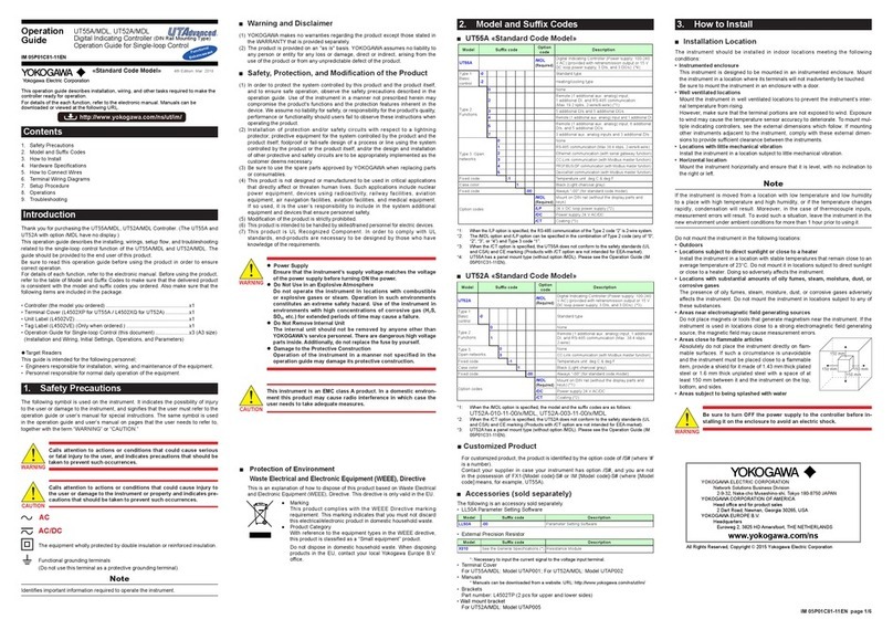
YOKOGAWA UT52A/MDL series User manual

YOKOGAWA

YOKOGAWA UT52A/MDL series User manual

YOKOGAWA Green Series User manual

YOKOGAWA

YOKOGAWA Green Series User manual

YOKOGAWA YS1700 User manual

YOKOGAWA

YOKOGAWA YS1700 User manual

YOKOGAWA UT350-01 User manual

YOKOGAWA

YOKOGAWA UT350-01 User manual

YOKOGAWA UT750 User manual

YOKOGAWA

YOKOGAWA UT750 User manual

YOKOGAWA UT351 User manual

YOKOGAWA

YOKOGAWA UT351 User manual

YOKOGAWA YS170 User manual

YOKOGAWA

YOKOGAWA YS170 User manual

YOKOGAWA UT150L User manual

YOKOGAWA

YOKOGAWA UT150L User manual

YOKOGAWA FA-M3 Vitesse Manual

YOKOGAWA

YOKOGAWA FA-M3 Vitesse Manual

YOKOGAWA UT75A User manual

YOKOGAWA

YOKOGAWA UT75A User manual

YOKOGAWA AQ2201 User manual

YOKOGAWA

YOKOGAWA AQ2201 User manual

YOKOGAWA UT150L User manual

YOKOGAWA

YOKOGAWA UT150L User manual

YOKOGAWA UTAdvanced UT35A Manual

YOKOGAWA

YOKOGAWA UTAdvanced UT35A Manual

YOKOGAWA UTAdvanced UT52A Manual

YOKOGAWA

YOKOGAWA UTAdvanced UT52A Manual

YOKOGAWA FA-M3 Vitesse Operating manual

YOKOGAWA

YOKOGAWA FA-M3 Vitesse Operating manual

YOKOGAWA Vitesse FA-M3V User manual

YOKOGAWA

YOKOGAWA Vitesse FA-M3V User manual

YOKOGAWA UT350 User manual

YOKOGAWA

YOKOGAWA UT350 User manual

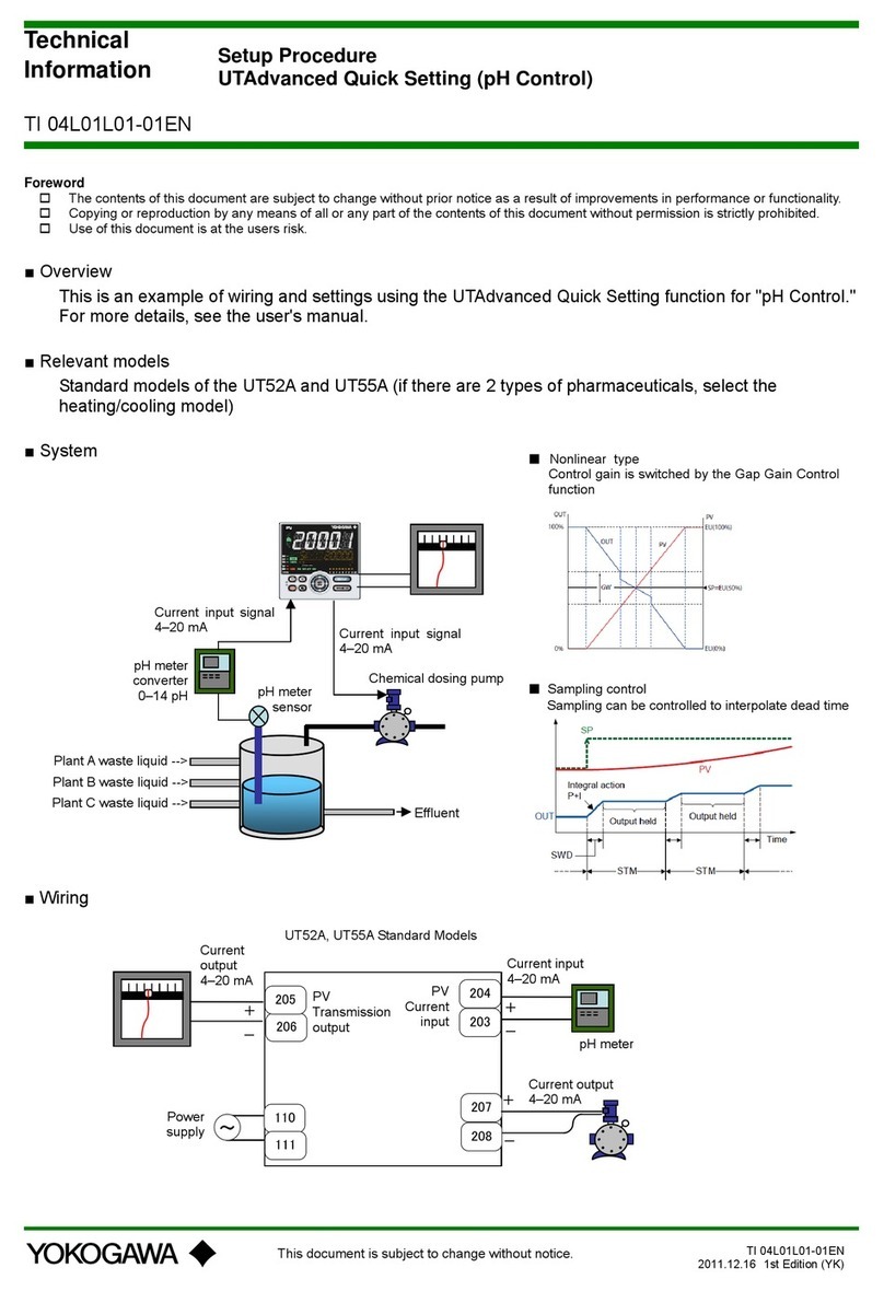
YOKOGAWA UTAdvanced UP55A User manual

YOKOGAWA

YOKOGAWA UTAdvanced UP55A User manual

YOKOGAWA UTAdvanced UT32A Manual

YOKOGAWA

YOKOGAWA UTAdvanced UT32A Manual

YOKOGAWA UM33A User manual

YOKOGAWA

YOKOGAWA UM33A User manual

YOKOGAWA UT520 User manual

YOKOGAWA

YOKOGAWA UT520 User manual

YOKOGAWA Revolution FA-M3 R Manual

YOKOGAWA

YOKOGAWA Revolution FA-M3 R Manual

YOKOGAWA DYNASERV DM Series User manual

YOKOGAWA

YOKOGAWA DYNASERV DM Series User manual

YOKOGAWA YS1000 Series User manual

YOKOGAWA

YOKOGAWA YS1000 Series User manual

Popular Controllers manuals by other brands

Wyze WSPRK1 manual

Wyze

Wyze WSPRK1 manual

InCoax In:xtnd user manual

InCoax

InCoax In:xtnd user manual

AVYCON AVK P2500 quick start guide

AVYCON

AVYCON AVK P2500 quick start guide

Komfovent DOMEKT Installation and operation manual

Komfovent

Komfovent DOMEKT Installation and operation manual

CDI 197-0001 Installation and troubleshooting guide

CDI

CDI 197-0001 Installation and troubleshooting guide

Aeotec Nano Shutter ZW141 quick start guide

Aeotec

Aeotec Nano Shutter ZW141 quick start guide

Hunter NODE-100 user manual

Hunter

Hunter NODE-100 user manual

Controlli NR9003 Mounting instructions

Controlli

Controlli NR9003 Mounting instructions

3Ware 9590SE Series User guide addendum

3Ware

3Ware 9590SE Series User guide addendum

Ewellix CAHB-2 Series Installation, operation and maintenance manual

Ewellix

Ewellix CAHB-2 Series Installation, operation and maintenance manual

Rehau RE.HUB quick start guide

Rehau

Rehau RE.HUB quick start guide

Phason PEC User manual and installation guide

Phason

Phason PEC User manual and installation guide

Media Pointe TAC-CR user manual

Media Pointe

Media Pointe TAC-CR user manual

Busch-Jaeger 6212/1.1-WL System manual

Busch-Jaeger

Busch-Jaeger 6212/1.1-WL System manual

Fiery AR-PE1 Installation and service guide

Fiery

Fiery AR-PE1 Installation and service guide

Doms PSS 5000 installation guide

Doms

Doms PSS 5000 installation guide

Plasson Water On Demand installation instructions

Plasson

Plasson Water On Demand installation instructions

QUANT QUANT-9 Operation manual

QUANT

QUANT QUANT-9 Operation manual

manuals.online logo
manuals.online logoBrands
  • About & Mission
  • Contact us
  • Privacy Policy
  • Terms and Conditions

Copyright 2025 Manuals.Online. All Rights Reserved.