IM 05P01C81-11EN page 1/6
Contents
1. Safety Precautions
2. ModelandSuxCodes
3. How to Install
4. HardwareSpecications
5. HowtoConnectWires
6. TerminalWiringDiagrams
7. Setup Procedure
8. Operations
9. Troubleshooting
Introduction
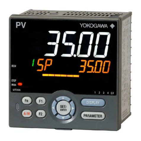
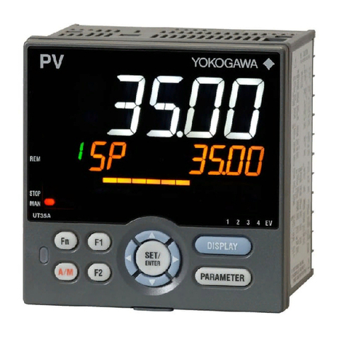
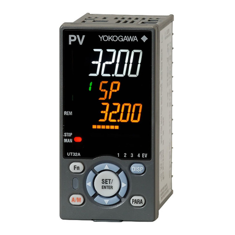
ThankyouforpurchasingtheUT55A/MDL,UT52A/MDLController.(TheUT55Aand
UT52Awithoption/MDLhavenodisplay.)
Thisoperationguidedescribestheinstalling,wirings,setupow,andtroubleshooting
relatedtothesingle-loopcontrolfunctionoftheUT55A/MDLandUT52A/MDL.The
guideshouldbeprovidedtotheenduserofthisproduct.
Besuretoreadthisoperationguidebeforeusing theproductinorder toensure
correct operation.
Fordetailsofeachfunction,refertotheelectronicmanual.Beforeusingtheproduct,
refertothetableofModelandSuxCodestomakesurethatthedeliveredproduct
isconsistentwiththemodelandsuxcodesyouordered.Alsomakesurethatthe
followingitemsareincludedinthepackage.
•Controller(themodelyouordered) .........................................................x1
•TerminalCover(L4502XPforUT55A/L4502XQforUT52A) ................x1
•UnitLabel(L4502VZ) ..............................................................................x1
•TagLabel(L4502VE)(Onlywhenordered.) ...........................................x1
•OperationGuideforSingle-loopControl(thisdocument) .......................x3(A3size)
(InstallationandWiring,InitialSettings,Operations,andParameters)
l
TargetReaders
Thisguideisintendedforthefollowingpersonnel;
• Engineersresponsibleforinstallation,wiring,andmaintenanceoftheequipment.
• Personnelresponsiblefornormaldailyoperationoftheequipment.
1. Safety Precautions
Thefollowingsymbolis usedonthe instrument.Itindicatesthepossibilityofinjury
totheuserordamagetotheinstrument,andsigniesthattheusermustrefertothe
operationguideoruser’smanualforspecialinstructions.Thesamesymbolisused
intheoperationguideanduser’smanualonpagesthat theuserneedstorefer to,
togetherwiththeterm“WARNING”or“CAUTION.”
Calls attention to actions or conditions that could cause serious
or fatal injury to the user, and indicates precautions that should be
taken to prevent such occurrences.
Calls attention to actions or conditions that could cause injury to
the user or damage to the instrument or property and indicates pre-
cautions that should be taken to prevent such occurrences.
Theequipmentwhollyprotectedbydoubleinsulationorreinforcedinsulation.
Functionalgroundingterminals
(Donotusethisterminalasaprotectivegroundingterminal).
Note
Identiesimportantinformationrequiredtooperatetheinstrument.
■Warning and Disclaimer
(1) YOKOGAWA makesno warrantiesregardingthe productexceptthosestated in
theWARRANTYthatisprovidedseparately.
(2) Theproductisprovidedonan"asis"basis.YOKOGAWAassumesnoliabilityto
anypersonorentityfor anylossordamage, directorindirect,arising fromthe
use of the product or from any unpredictable defect of the product.
■ Safety,Protection,andModicationoftheProduct
(1)Inorder toprotectthe systemcontrolledbythisproductandthe productitself,
andtoensuresafe operation,observethesafetyprecautionsdescribedinthe
operationguide.Useoftheinstrumentin amannernot prescribedhereinmay
compromise the product's functions and the protection features inherent in the
device.Weassumenoliabilityforsafety,orresponsibilityfortheproduct'squality,
performanceorfunctionalityshouldusersfailtoobservetheseinstructionswhen
operatingtheproduct.
(2)Installation ofprotectionand/or safetycircuitswithrespect toalightning
protector;protectiveequipmentforthesystemcontrolledbytheproductandthe
productitself;foolprooforfail-safedesignofaprocessorlineusingthesystem
controlledbytheproductortheproductitself;and/orthedesignandinstallation
ofotherprotectiveandsafetycircuitsaretobeappropriatelyimplementedasthe
customer deems necessary.
(3) Be sureto usethe spare partsapproved byYOKOGAWAwhen replacingparts
or consumables.
(4) This productis notdesigned or manufacturedto be usedin criticalapplications
thatdirectlyaffectorthreatenhumanlives.Such applicationsincludenuclear
powerequipment,devicesusingradioactivity,railwayfacilities, aviation
equipment,airnavigationfacilities,aviationfacilities, andmedicalequipment.
Ifsoused,it istheuser’sresponsibilityto includeinthe systemadditional
equipmentanddevicesthatensurepersonnelsafety.
(5) Modicationoftheproductisstrictlyprohibited.
(6)
Thisproductisintendedtobehandledbyskilled/trainedpersonnelforelectricdevices.
(7)Thisproductis ULRecognizedComponent. Inordertocomply withUL
standards,end-productsarenecessaryto bedesignedby thosewhohave
knowledgeoftherequirements.
l
Power Supply
Ensure that the instrument’s supply voltage matches the voltage
of the power supply before turning ON the power.
lDo Not Use in an Explosive Atmosphere
Do not operate the instrument in locations with combustible
or explosive gases or steam. Operation in such environments
constitutes an extreme safety hazard. Use of the instrument in
environments with high concentrations of corrosive gas (H2S,
SOX, etc.) for extended periods of time may cause a failure.
lDo Not Remove Internal Unit
The internal unit should not be removed by anyone other than
YOKOGAWA's service personnel. There are dangerous high voltage
parts inside. Additionally, do not replace the fuse by yourself.
lDamage to the Protective Construction
Operation of the instrument in a manner not specified in the
operation guide may damage its protective construction.
This instrument is an EMC class A product. In a domestic environ-
ment this product may cause radio interference in which case the
user needs to take adequate measures.
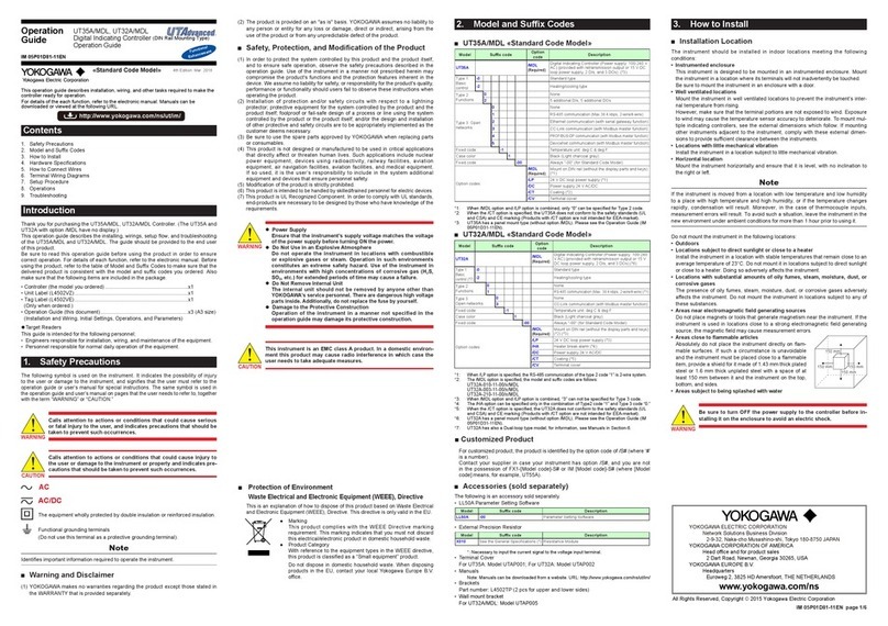
2. ModelandSuxCodes
■UT55A «Standard Code Model»
Model Suxcode Option
code Description
UT55A /MDL
(Required)
DigitalIndicatingController(Powersupply:100-240
VAC)(providedwithretransmissionoutputor15V
DClooppowersupply,3DIs,and3DOs)(*4)
Type1:
Basic
control
-0 Standard type
-2 Heating/coolingtype
Type2:
Functions
0None
2
Remote(1additionalaux.analog)input,
1additionalDI,andRS-485communication
(Max.19.2kpbs,2-wire/4-wire)(*1)
35additionalDIsand5additionalDOs
4
Remote(1additionalaux.analog)inputand1additionalDI
5Remote(1additionalaux.analog)input,6additional
DIs,and5additionalDOs
73additionalaux.analoginputsand3additionalDIs
Type3:Open
networks
0None
1
RS-485communication(Max.38.4kbps,2-wire/4-wire)
2
Ethernetcommunication(withserialgatewayfunction)
3
CC-Linkcommunication(withModbusmasterfunction)
4
PROFIBUS-DPcommunication(withModbusmasterfunction)
5
DeviceNetcommunication(withModbusmasterfunction)
Fixedcode -1
Temperatureunit:degC°F
Casecolor 1Black(Lightcharcoalgray)
Fixedcode -00 Always"-00"(forstandardcodemodel)
Option codes
/MDL
(Required)
MountonDINrail(withoutthedisplaypartsand
keys)
/LP 24VDClooppowersupply(*2)
/DC Powersupply24VAC/DC
/CT Coating(*3)
*1:
Whenthe/LPoptionisspecified,theRS-485communicationoftheType2code“2”is2-wiresystem.
*2: The/MDLoptionand/LPoptioncanbespecifiedinthecombinationofType2code(anyof“0”,
“2”,“3”,or“4”)andType3code“1”.
*3: Whenthe/CToptionisspecified,theUT55Adoesnotconformtothesafetystandards(UL
andCSA)andCEmarking(Productswith/CToptionarenotintendedforEEA-market).
*4: UT55Ahasapanelmounttype(withoutoption/MDL).PleaseseetheOperationGuide(IM
05P01C31-11EN).
■UT52A «Standard Code Model»
Model Suxcode Option
code Description
UT52A /MDL
(Required)
DigitalIndicatingController(Powersupply:100-240
VAC)(providedwithretransmissionoutputor15V
DClooppowersupply,3DIs,and3DOs)(*3)
Type1:
Basic
control
-0 Standard type
Type2:
Functions
0None
1
Remote(1additionalaux.analog)input,1additional
DI,andRS-485communication(Max.38.4kbps,
2-wire)
Type3:
Open networks
0None
3
CC-Linkcommunication(withModbusmasterfunction)
Fixedcode -1
Temperatureunit:degC°F
Casecolor 1Black(Lightcharcoalgray)
Fixedcode -00 Always"-00"(forstandardcodemodel)
Option codes
/MDL
(Required)
MountonDINrail(withoutthedisplaypartsand
keys)(*1)
/DC Powersupply24VAC/DC
/CT Coating(*2)
*1: Whenthe/MDLoptionisspecified,themodelandthesuffixcodesareasfollows:
UT52A-010-11-00/x/MDL,UT52A-003-11-00/x/MDL
*2: Whenthe/CToptionisspecified,theUT52Adoesnotconformtothesafetystandards(UL
andCSA)andCEmarking(Productswith/CToptionarenotintendedforEEA-market).
*3: UT52Ahasapanelmounttype(withoutoption/MDL).PleaseseetheOperationGuide(IM
05P01C31-11EN).
■CustomizedProduct
Forcustomizedproduct,theproductisidentiedbytheoptioncodeof/S#(where‘#’
isanumber).
Contactyoursupplier incaseyour instrumenthasoption/S#,andyou arenot
inthepossessionof FX1-[Modelcode]-S#or IM[Modelcode]-S#(where[Model
code]means,forexample,UT55A).
■Accessories (sold separately)
Thefollowingisanaccessorysoldseparately.
• LL50AParameterSettingSoftware
Model Suxcode Description
LL50A -00 ParameterSettingSoftware
• ExternalPrecisionResistor
Model Suxcode Description
X010 SeetheGeneralSpecications(*) ResistanceModule
*:Necessarytoinputthecurrentsignaltothevoltageinputterminal.
• TerminalCover
ForUT55A/MDL:ModelUTAP001;ForUT52A/MDL:ModelUTAP002
• Manuals
*Manualscanbedownloadedfromawebsite.URL:http://www.yokogawa.com/ns/ut/im/
• Brackets
Partnumber:L4502TP(2pcsforupperandlowersides)
•Wallmountbracket
ForUT52A/MDL:ModelUTAP005
3. How to Install
■Installation Location
Theinstrumentshouldbe installedinindoor locationsmeetingthe following
conditions:
• Instrumented enclosure
Thisinstrumentisdesigned tobemountedin aninstrumentedenclosure. Mount
theinstrumentinalocationwhereitsterminalswillnotinadvertentlybetouched.
Be sure to mount the instrument in an enclosure with a door.
• Well ventilated locations
Mounttheinstrumentinwellventilatedlocationstopreventtheinstrument’sinter-
naltemperaturefromrising.
However,makesurethattheterminalportionsarenotexposedtowind.Exposure
to wind may cause the temperature sensor accuracy to deteriorate. To mount mul-
tipleindicatingcontrollers,see theexternaldimensions whichfollow.Ifmounting
otherinstrumentsadjacent totheinstrument, complywith theseexternaldimen-
sionstoprovidesucientclearancebetweentheinstruments.
• Locations with little mechanical vibration
Installtheinstrumentinalocationsubjecttolittlemechanicalvibration.
• Horizontal location
Mounttheinstrumenthorizontallyandensurethatitislevel,withnoinclinationto
therightorleft.
Note
Iftheinstrumentismovedfrom alocationwith lowtemperatureand lowhumidity
toaplacewithhigh temperatureandhighhumidity,orifthetemperaturechanges
rapidly,condensationwill result.Moreover,in thecaseof thermocoupleinputs,
measurementerrorswillresult.Toavoidsuchasituation,leavetheinstrumentinthe
newenvironmentunderambientconditionsformorethan1hourpriortousingit.
Donotmounttheinstrumentinthefollowinglocations:
• Outdoors
• Locations subject to direct sunlight or close to a heater
Install the instrument in a location with stable temperatures that remain close to an
averagetemperatureof23°C.Donotmountitinlocationssubjecttodirectsunlight
orclosetoaheater.Doingsoadverselyaectstheinstrument.
• Locations with substantial amounts of oily fumes, steam, moisture, dust, or
corrosive gases
Thepresenceof oilyfumes,steam, moisture,dust,or corrosivegases adversely
aectstheinstrument.Donotmounttheinstrumentinlocationssubjecttoanyof
these substances.
• Areasnearelectromagneticeldgeneratingsources
Donotplacemagnetsortoolsthatgeneratemagnetismneartheinstrument.Ifthe
instrumentisusedinlocations closetoastrong electromagneticeldgenerating
source,themagneticeldmaycausemeasurementerrors.
• Areasclosetoammablearticles
Absolutelydonotplace theinstrumentdirectlyon am-
mablesurfaces.Ifsuch acircumstanceis unavoidable
andtheinstrumentmustbeplacedclosetoaammable
item,provideashieldforitmadeof1.43mmthickplated
steel or 1.6 mm thick unplated steel with a space of at
least150mmbetweenitandtheinstrumentonthetop,
bottom,andsides.
• Areas subject to being splashed with water
Be sure to turn OFF the power supply to the controller before in-
stalling it on the enclosure to avoid an electric shock.
www.yokogawa.com/ns
YOKOGAWA ELECTRIC CORPORATION
Network Solutions Business Division
2-9-32, Naka-cho Musashino-shi, Tokyo 180-8750 JAPAN
YOKOGAWA CORPORATION OF AMERICA
Head office and for product sales
2 Dart Road, Newnan, Georgia 30265, USA
YOKOGAWA EUROPE B.V.
Headquarters
Euroweg 2, 3825 HD Amersfoort, THE NETHERLANDS
All Rights Reserved, Copyright © 2015 Yokogawa Electric Corporation
150 mm150 mm
150 mm
150 mm
Operation
Guide
IM 05P01C81-11EN
UT55A/MDL, UT52A/MDL
Digital Indicating Controller (DIN Rail Mounting Type)
Operation Guide for Single-loop Control
This operation guide describes installation, wiring, and other tasks required to make the
controller ready for operation.
4th Edition: Mar. 2018
For details of the each function, refer to the electronic manual. Manuals can be
downloaded or viewed at the following URL.
Functional
Enhancement
http://www.yokogawa.com/ns/ut/im/
«Standard Code Model»
■Protection of Environment
Waste Electrical and Electronic Equipment (WEEE), Directive
ThisisanexplanationofhowtodisposeofthisproductbasedonWasteElectrical
andElectronicEquipment(WEEE),Directive.ThisdirectiveisonlyvalidintheEU.
● Marking
ThisproductcomplieswiththeWEEEDirectivemarking
requirement.Thismarkingindicatesthatyoumustnotdiscard
thiselectrical/electronicproductindomestichouseholdwaste.
● ProductCategory
WithreferencetotheequipmenttypesintheWEEEdirective,
thisproductisclassiedasa“Smallequipment”product.
Donot dispose in domestichouseholdwaste. When disposing
products in the EU, contact your localYokogawa Europe B.V.
oce.
