IM 01F07A03-02EN
1
<1. Introduction> 1
1. Introduction
This manual provides the basic guidelines for
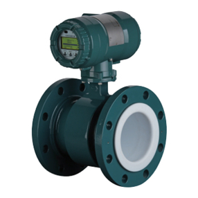
explosion protection type of Vortex owmeter VY
Series.
For the items which are not covered in this manual,
read the applicable user’s manuals and general
specications as listed in IM 01F07A21-01Z1 (Read
Me First). To ensure correct use of the product, read
these manuals thoroughly and fully understand how
to operate the product before maintaining it. For
method of checking the model and specications,
read the general specications GS 01F07A00-
01EN.
Website address: http://www.yokogawa.com/d/doc/
These manuals can be downloaded from the
website of YOKOGAWA or purchased from the
YOKOGAWA representatives.
When describing the model name like “VY###” in
this manual, “###” means any of the following.
For VY###:
015, 025, 040, 050, 080, 100, 150, 200, 250,
300, 400
Precautions Related to the Protection,
Safety, and Alteration of the Product
The following safety symbol marks are used in this
manual and product.
WARNING
A WARNING sign denotes a hazard. It calls
attention to procedure, practice, condition or the
like, which, if not correctly performed or adhered
to, could result in injury or death of personnel.
CAUTION
A CAUTION sign denotes a hazard. It calls
attention to procedure, practice, condition or the
like, which, if not correctly performed or adhered
to, could result in damage to or destruction of
part or the entire product.
An IMPORTANT sign denotes that attention
is required to avoid damage to the product or
system failure.
A NOTE sign denotes information necessary
for essential understanding of operation and
features.
The following symbols are used in the product and
the manual to indicate the accompanying safety
precautions:
Functional grounding terminal
Direct current
Caution
This symbol indicates that the operator must refer to
an explanation in the user’s manual in order to avoid
the risk of injury or death of personnel or damage to
the product.
•
For the protection and safe use of the product
and the system in which this product is
incorporated, be sure to follow the instructions
and precautions on safety that is stated in user's
manual as listed in IM 01F07A21-01Z1 (Read
Me First) whenever you handle the product.
Take special note that if you handle the product
in a manner that violated these instructions,
the protection functionality of the product
may be damaged or impaired. In such cases,
YOKOGAWA does not guarantee the quality,
performance, function, and safety of product.
•
Do not modify this product.
•
The product should be disposed of in accordance
with local and national legislation/ regulations.
