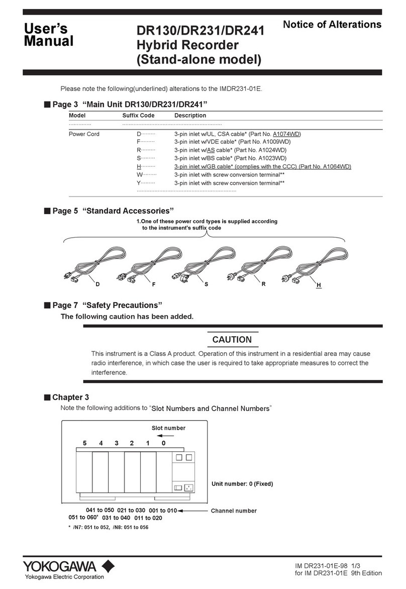
YOKOGAWA FX1000 User manual

IM 04L21B01-03EN page 1/4
Introduction
Thank you for purchasing the FX1002, FX1004, FX1006, FX1008, FX1010, or FX1012 Paperless
Recorder (hereafter referred to as “FX” or “FX1000”.). This manual describes the safty precautions
and installation and wiring procedures of the FX1000.
To ensure correct use, please read this manual and the manuals below thoroughly before
beginning operation. For the product specications, see the general specications.
Paper Manual
Manual Title Manual No.*
Model FX1002/FX1004/FX1006/FX1008/FX1010/FX1012
FX1000 Paperless Recorder Safety Precautions and Installation Guide
Installing the FXA120 DAQSTANDARD
FX1000 Mode Transition Diagram
Setting Mode / Basic Setting Mode Maps (This manual)
IM 04L21B01-03EN
Electronic Manuals
You can download these manuals from the following web page. You will need Adobe Reader 7 or
later (latest version recommended) by Adobe Systems.
http://www.yokogawa.com/ns/fx1000/im/
Manual Title Manual No.*
Model FX1002/FX1004/FX1006/FX1008/FX1010/FX1012
FX1000 Paperless Recorder User’s Manual
IM 04L21B01-01EN
Model FX1002/FX1004/FX1006/FX1008/FX1010/FX1012
FX1000 Paperless Recorder First Step Guide
IM 04L21B01-02EN
Model FX1002/FX1004/FX1006/FX1008/FX1010/FX1012
FX1000 Paperless Recorder Safety Precautions and Installation Guide
Installing the FXA120 DAQSTANDARD
FX1000 Mode Transition Diagram
Setting Mode / Basic Setting Mode Maps
IM 04L21B01-03EN
Model FX1002/FX1004/FX1006/FX1008/FX1010/FX1012
FX1000 Paperless Recorder Communication Interface (/C2, /C3, and /C7)
IM 04L21B01-17EN
FXA120 DAQSTANDARD for FX1000 Data Viewer IM 04L21B01-63EN
FXA120 DAQSTANDARD for FX1000 Hardware Configurator IM 04L21B01-64EN
Model FX1002/FX1004/FX1006/FX1008/FX1010/FX1012
FX1000 Paperless Recorder Usage Precautions
IM 04L21B01-91EN
General Specications (GS)
General Specifications Name General Specifications No.*
Model FX1002/FX1004/FX1006/FX1008/FX1010/FX1012
FX1000 Paperless Recorder
GS 04L21B0-02EN
* The last two characters of the manual number and the general specications number indicate
the language in which the manuals or general specications are written.
The Authorised Representative for this product in the EEA is:
Yokogawa Europe B.V.
Euroweg 2, 3825 HD Amersfoort,The Netherlands
Model and Sufx Codes
A name plate is located on the top panel of the FX. Check that the model name and sufx code
given on the name plate match those on your order.
name plate
Model
code
Suffix code
Optional
code
Description
FX1002
2ch, Shortest measurement interval:125ms
FX1004
4ch, Shortest measurement interval:125ms
FX1006 6ch, Shortest measurement interval:1s
FX1008 8ch, Shortest measurement interval:1s
FX1010
10ch, Shortest measurement interval:1s
FX1012
12ch, Shortest measurement interval:1s
External
storage
medium
slot
-0 Without CF card slot/SD card slot and medium
(Note)
-4 With CF card slot and medium
-7 With SD card slot and medium
Language -2
English/German/French/Italian/ Spanish/
Portuguese/ Russian/ Korean
deg F and DST
Withstanding
voltage between
measuring input
terminals
-H 1000 VAC(50/60 Hz), 1 min
-L 400 VAC(50/60 Hz), 1 min
Options /A1 Alarm output 2 points (C-contact)*1*10
/A2 Alarm output 4 points (C-contact)*1
/A3 Alarm output 6 points (C-contact)*1*3
/A4A Alarm output 12 points (A-contact)*1*3
/C2 RS-232 interface*2
/C3 RS-422A/485 interface*2
/C7 Ethernet interface
/F1 FAIL/Status output*3
/M1
Mathematical functions (including Report functions)
/N2 3 leg isolated RTD*4
/N3F Extended input type (without Pt1000)
/P1 24 VDC/AC power supply
/R1 Remote control 8 points*5
/TPS2 24VDC transmitter power supply (2 loops)*6*10
/TPS4 24VDC transmitter power suply (4 loops)*7
/USB1 USB interface (1 port)
/PM1 Pulse input 3 points, Remote control 5 points
(including Mathematical functions)*8
/CC1 Calibration correction function
/LG1 Log scale
/PWR1 Power monitor (1 A input, including Mathmatical
functions)*9*10
/PWR5 Power monitor (5 A input, including Mathmatical
functions)*10*11
/S# Customized product; details in IM FX1K-S#E*12
Note: To load data, the FX must be equipped with a communication interface (/C2, /
C3 or /C7 option) or the USB interface (/USB1 option.)
*1 Any combination of /A1, /A2, /A3, and /A4A cannot be specied together.
*2 /C2 and /C3 cannot be specied together.
*3 /A3 or /A4A cannot be specied together with /F1.
*4 /N2 cannot be specied for FX1002 or FX1004.
*5 If /R1 is specied, /A4A, /TPS2, /TPS4, /PM1, /PWR1, or /PWR5 cannot be specied.
*6 If /TPS2 is specied, /TPS4, /A2, /A3, /A4A, /F1, /R1, or /PM1 cannot be specied.
*7 If /TPS4 is specied, /TPS2, /A1, /A2, /A3, /A4A, /F1, /R1, or /PM1 cannot be specied.
*8 If /PM1 is specied, /A4A, /M1, /R1, /TPS2, /TPS4, /PWR1, or /PWR5 cannot be specied.
*9 If /PWR1 is specified, /A3, /A4A, /F1, /R1, /PM1, /M1, or /PWR5 cannot be
specied.
*10 /TPS2, /PWR1, and /A1 cannot be specied together. /TPS2, /PWR5, and /A1
cannot be specied together.
*11 If /PWR5 is specied, /A3, /A4A, /F1, /R1, /PM1, /M1, or /PWR1 cannot be specied.
*12 Contact your supplier in case your instrument has option /S# (where ‘#’ is a
number), and you are not in the possession of IM FX1K-S#E.
Standard Accessories
The standard accessories below are supplied with the instrument. Check that all
contents are present and undamaged.
1 2
5
46
No. Name Model Qty. Notes
1 Mounting brackets B8730BU 2 For panel
mounting
2Rubber packing for dust and water
protection
- 1 For single-unit
mounting
4 Model FX1002/FX1004/FX1006/FX1008/
FX1010/FX1012
FX1000 Paperless Recorder Safety
Precautions and Installation Guide
Installing the FXA120 DAQSTANDARD
FX1000 Mode Transition Diagram
Setting Mode / Basic Setting Mode Maps
IM 04L21B01-
03EN
1 A3 size
5 CF card*1 772093 1 512 MB
6 SD card*2 773001 1 1 GB
*1 On FXs that have a CF card slot (sufx code -4.)
CF card capacity is subject to change.
*2 On FXs that have a SD card slot (sufx code -7.)
SD card capacity is subject to change.
*3 For optional accessories (Sold Separately), see the IM 04L21B01-02EN.
Softoware (FXA120 DAQSTANDARD for FX1000), Label
Please download the software and the label data from the following web page.
http://www.yokogawa.com/ns/fx1000/soft/
Item Description
Software FXA120 DAQSTANDARD for FX1000
Consists of the Data Viewer and the Hardware Configurator.
Label Labels to Attach to the FX1000 Operation Cover
Download the label data (Excel file). Print the label that you want to use.
Label size: 19 ± 0.3 mm tall and 90 ± 0.3 mm wide
File name: IM04L21B01-81Z1.xls
1. Safety Precautions
The following safety symbols are used on the product and in this manual.
WARNING
Calls attention to actions or conditions that could cause serious
or fatal injury to the user, and indicates precautions that should be
taken to prevent such occurrences.
CAUTION
Calls attention to actions or conditions that could cause injury to
the user or damage to the instrument or property and indicates pre-
cautions that should be taken to prevent such occurrences.
Protective ground terminal
Alternating current
Direct current
“Handle with care.” To avoid injury and damage to
the instrument, the operator must refer to the
explanation in the manual.
Note
Identies important information required to operate the instrument.
nSafety Precautions
• This instrument conforms to IEC safety class I (provided with terminal for protec-
tive grounding), Installation Category II, and EN61326-1 (EMC standard), Mea-
surement Category II (CAT II)*.
* Measurement category II (CAT II) applies to measuring circuits connected to low voltage
installation, and electrical instruments supplied with power from fixed equipment such as
electric switchboards.
• This instrument is an EN61326-1 (EMC standard) class A instrument (for use in
commercial, industrial, or business environments). The inuence rate (judgment
condition A) in the immunity test environment is within ±15 % of the range or ±10
mV.
• The general safety precautions described here must be observed during all phases
of operation. If the FX is used in a manner not described in this manual, the FX
safety features may be impaired. Yokogawa Electric Corporation assumes no li-
ability for the customer’s failure to comply with these requirements.
• The FX is designed for indoor use.
n About User’s Manual
• Please pass user’s manuals to the end user. We also ask you to store manuals in
a safe place.
• Read user’s manuals thoroughly and have a clear understanding of the product
before operation.
• User’s manuals explain the functions of the product. It does not guarantee that the
product will suit a particular purpose of the user.
n
Precautions Related to the Protection, Safety, and Alteration of the Product
• For the protection and safe use of the product and the system in which this product
is incorporated, be sure to follow the instructions and precautions on safety that are
stated in this manual whenever you handle the product. Take special note that if you
handle the product in a manner that violates these instructions, the protection function-
ality of the product may be damaged or impaired. In such cases, YOKOGAWA does
not guarantee the quality, performance, function, and safety of product.
• When installing protection and/or safety circuits such as lightning protection devices
and equipment for the product and control system or designing or installing separate
protection and/or safety circuits for fool-proof design and fail-safe design of the pro-
cesses and lines that use the product and the control system, the user should imple-
ment these using additional devices and equipment.
• If you are replacing parts or consumable items of the product, make sure to use parts
specied by YOKOGAWA.
•
This product is not designed or manufactured to be used in critical applications that di-
rectly affect or threaten human lives. Such applications include nuclear power equipment,
devices using radioactivity, railway facilities, aviation equipment, air navigation facilities,
aviation facilities, and medical equipment. If so used, it is the user’s responsibility to in-
clude in the system additional equipment and devices that ensure personnel safety.
• Do not modify this product.
WARNING
l Use the Correct Power Supply
Ensure that the source voltage matches the voltage of the power
supply before turning ON the power.
l Connect the Protective Grounding Terminal
Make sure to connect the protective grounding to prevent
electric shock before turning ON the power.
lDo Not Impair the Protective Grounding
Never cut off the internal or external protective grounding wire
or disconnect the wiring of the protective grounding terminal.
Doing so invalidates the protective functions of the instrument
and poses a potential shock hazard.
lDo Not Operate with Defective Protective Grounding
Do not operate the instrument if the protective grounding might
be defective. Also, make sure to check them before operation.
lDo Not Operate in an Explosive Atmosphere
Do not operate the instrument in the presence of flammable
liquids or vapors. Operation in such an environment constitutes
a safety hazard. Prolonged use in a highly dense corrosive gas
(H2S, SOx, etc.) will cause a malfunction.
l Do Not Remove Covers
The cover should be removed by YOKOGAWA’s qualified
personnel only. Opening the cover is dangerous, because some
areas inside the instrument have high voltages.
l Ground the Instrument before Making External Connections
Connect the protective grounding before connecting to the item
under measurement or control unit.
lDamage to the Protection
Operating the instrument in a manner not described in this
manual may damage the instrument’s protection.
CAUTION
This instrument is a Class A product. Operation of this instrument in a
residential area may cause radio interference, in which case the user is
required to take appropriate measures to correct the interference.
n Exemption from Responsibility
• YOKOGAWA makes no warranties regarding the product except those stated in
the WARRANTY that is provided separately.
• YOKOGAWA assumes no liability to any party for any loss or damage, direct or
indirect, caused by the user or any unpredictable defect of the product.
2. Installation
nInstallation Location
Install the FX indoors in an environment that meets the following conditions:
• Instrumentation Panel
The FX is designed to be installed in an instrumentation panel.
• Well-Ventilated Location
To prevent overheating, install the FX in a well-ventilated location. For the panel
cut dimensions when arranging multiple FXs, see “External Dimensions and Panel
Cutout Dimensions.” When other instruments are installed next to the FX, follow
the panel cut dimensions to provide adequate space around the FX.
• Minimal Mechanical Vibrations
Install the FX in a location that has minimal mechanical vibrations. Installing the FX
in a location that is subject to large levels of mechanical vibration will not only put
added stress on its components, it may also impede ordinary measurement.
• Level Location
Install the FX in a level location so that it is not slanted to the left or the right (how-
ever, the FX can be inclined up to 30 degrees backward for panel mounting).
Note
Condensation may form when moving the FX from an environment whose temperature or
humidity is low to an environment whose temperature or humidity is high, or when there
is a sudden change in temperature. Temperature or humidity changes may also result in
thermocouple measurement errors. In these kinds of circumstances, let the FX adjust to
the new environment for at least an hour before using it.
Do not install the FX in the following places.
• Outdoors
• In Direct Sunlight or Near Heat Sources
Install the FX in a place that is near room temperature (23°C) and that is not sub-
ject to large temperature uctuations. Placing the FX in direct sunlight or near heat
sources can cause adverse effects on the internal circuitry.
• Where an Excessive Amount of Soot, Steam, Moisture, Dust, or Corrosive
Gases Are Present
Soot, steam, moisture, dust, and corrosive gases will adversely affect the FX.
Avoid installing the FX in such locations.
• Near Strong Magnetic Field Sources
Do not bring magnets or instruments that produce electromagnetic elds close to the
FX. Operating the FX near strong magnetic elds can cause measurement errors.
• Where the Display Is Difcult to See
The FX uses an LCD screen, so it is difcult to view the display from an extreme
angle. Install the FX so that the user can view the display directly from the front.
nInstallation Procedure
Use a steel panel that is 2 mm to 26 mm thick.
1) Insert the FX through the front of the panel.
2)
Mount the FX to the panel using the included mounting brackets as shown in the gure below.
Installation
Guide
IM 04L21B01-03EN
Model FX1002/FX1004/FX1006
/FX1008/FX1010/FX1012
FX1000 Paperless Recorder
Safety Precautions and
Installation Guide
6th Edition : Nov. 2017
IM 04L21B01-03EN page 2/4
•
Use two mounting brackets to support the top and bottom or the left and right sides of the
case (remove the stickers that are covering the holes before you attach the brackets).
• Follow the procedure below to mount the FX to the panel.
•
First, attach the two mounting brackets and temporarily tighten the mounting screws.
•
Next, x the FX in place by tightening the mounting screws with the appropriate torque.
When the FX is approximately perpendicular to the panel, press the mounting brackets
so that they are in contact with the case, and fully tighten the mounting screws.
• Tighten the mounting bracket screws until you hear clicks.
CAUTION
l Using more than the appropriate torque to tighten the screws
can deform the case or damage the brackets.
l Be sure not to insert foreign objects or tools into the case
through the mounting bracket holes.
l Do not touch the screw at the top of the mounting bracket
(A). Loosening or tightening this screw may cause the FX to
malfunction.
Front
Panel
Panel Mounting bracket
Mounting bracket
Torque driver
(Phillips or flat blade)
Mounting screw
FX case
Attach firmly
(In the figure, the mounting brackets are used on the top and bottom of the case.)
Mounting screw
Screws temporarily fastened Fixed
Rubber packing for dust
and water protection
(except side-by-side
mounting)
A
Note
To achieve sufcient dust proong and waterproong, mount the FX in the middle of
the panel cut out. However, do not use the rubber packing if you are mounting two
instruments side by side or one on top of the other.
nExternal Dimensions and Panel Cutout Dimensions
136.5 +0.4
0
Unit: mm (approx. inch)
If not specified, the tolerance is ±3%.
However, in cases of less than 10mm, the tolerance is ±0.3 mm.
Panel thickness
(Dimensions after attaching
the mounting bracket)
If not installing the rubber packing for dust and water protection,
*1: 20.2 (0.80), *2: 163.7 (6.44), *3: 110.0 (4.33).
(*1) (*2)
(*3)
(Dimensions after attaching
the mounting bracket)
136.5
(5.37)
144.0 (5.67)
161.7 (6.37)
72.0 (2.83)
72.0 (2.83)
12.6
(0.50) 12.6 (0.50)
±0.3(0.01)
(2.74)
74.5 (2.93)
161.7 (6.37)
22.2 (0.87) 161.7 (6.37)
108.0 (4.25)
144.0 (5.67)
2 to 26
(0.08 to 1.02)
Mounting bracket
69.5
Panel cut dimensions
MIN 175
(6.89)
L
+ 2 (0.08)
0
137 (5.39)+ 2 (0.08)
0
Side-by side mounting
(vertically; max. 3 units)
137
(5.39)
MIN 175
(6.89)
0
L+ 2 (0.08)
0
Side-by-side mounting
(horizontally)
137 (5.39)+ 2 (0.08)
0
137
(5.39)
+ 2 (0.08)
0
Single-unit mounting
L
+ 2 (0.08)
0
2
3
4
5
6
7
8
9
10
n
282 (11.10)
426 (16.77)
in mm (approx. inches)
570 (22.44)
714 (28.11)
858 (33.78)
1434 (56.46)
1290 (50.79)
1146 (45.12)
1002 (39.45)
(144 × n) – 6 [(5.67 × n) – 0.24]
Units
+ 2 (0.08)
External dimensions
3. Wiring
nInput Signal Wiring
WARNING
To prevent electric shock while wiring, make sure that the power
supply is turned off.
CAUTION
l Applying a strong tension to the input and output signal cables
connected to the FX may damage the cables or the FX terminals.
To avoid applying tension directly to the terminals, fix all cables
to the rear of the mounting panel.
l
To prevent fire, use signal cables with a temperature rating of 80°C
or more.
lDo not apply voltages that exceed the following values to the
input terminals. Doing so may damage the FX.
• Maximum input voltage: ±60 VDC
• Maximum common mode voltage: ±60 VDC (under
measurement category II conditions)
l The FX is an installation category II product.
Precautions to Be Taken While Wiring
Take the following precautions when wiring the input signal cables.
When using a screw terminal, we recommend that you use a crimp-on lug with an
insulation sleeve (designed for 3 mm screws).
Take measures to prevent noise from entering the measurement circuit.
•
Move the measurement circuit away from the power cable (power circuit) and ground circuit.
• Ideally, the object being measured should not generate noise. However, if this is
unavoidable, isolate the measurement circuit from the object. Also, ground the ob-
ject being measured.
• Shielded wires should be used to minimize the noise caused by electrostatic induc-
tion. Connect the shield to the ground terminal of the FX as necessary (make sure
you are not grounding at two points).
• To minimize noise caused by electromagnetic induction, twist the measurement
circuit wires at short, equal intervals.
• Make sure to earth ground the protective ground terminal through minimum resis-
tance (less than 100 Ω).
When using internal reference junction compensation on the thermocouple input,
take measures to stabilize the temperature at the input terminal.
• Always use the terminal cover.
• Do not use thick wires which may cause large heat dissipation (we recommend a
cross sectional area of 0.5 mm2or less).
• Make sure that the ambient temperature remains reasonably stable. Large tem-
perature uctuations can occur if a nearby fan turns on or off.
Connecting the input wires in parallel with other devices can cause signal degradation,
affecting all connected devices. If you need to make a parallel connection, then
• Turn the burnout detection function off.
• Ground the instruments to the same point.
• Do not turn other instruments on or off during operation. This can have adverse ef-
fects on the other instruments.
• RTDs cannot be wired in parallel.
Input terminal block
of the FX1002
Input terminal block
of the FX1004
Input terminal block
of the FX1006
Input terminal block
of the FX1008
Input terminal block
of the FX1010
Input terminal block
of the FX1012
For TC input, use shielded compensating lead wires for wiring.
For RTD input, lead wire resistance per wire of 10 Ω or less. Make the resistances of
the three wires equal.
For DCA input, example: for 4 to 20 mA input, use a shunt resistor of 250 Ω ± 0.1%.
+/A
/b
CH1
–/B
CH2
+/A
/b
CH1
–/B
CH2CH3CH4
+/A
/b
CH1
–/B
CH2CH3CH4CH5CH6
+/A
/b
CH1
CH7
–/B
CH2
CH8
CH3CH4CH5CH6
+/A
/b
CH1
CH7
–/B
CH2
CH8
CH9CH10
CH3CH4CH5CH6
+/A
/b
CH1
CH7
–/B
CH2
CH8
CH9CH10CH11CH12
CH3CH4CH5CH6
Note
RTD input terminals A and B are isolated on each channel. Terminal b is shorted
internally across all channels. However, terminal b is also isolated on each channel
on models with the /N2 option (3 leg isolated RTD).
n
Optional Terminal Wiring
WARNING
l To prevent electric shock while wiring, make sure that the power
supply is turned off.
l If a voltage of more than 30 VAC or 60 VDC is to be applied to the
output terminals, use ring-tongue crimp-on lugs with insulation
sleeves on all terminals to prevent the signal cables from
slipping out when the screws become loose. Furthermore, use
double-insulated cables (dielectric strength of 3000 VAC or more)
for the signal cables on which a voltage of 30 VAC or 60 VDC
or more is to be applied. For all other signal cables, use basic
insulated cables (dielectric strength of 1500 VAC). To prevent
electric shock, attach the terminal cover after wiring and make
sure not to touch the terminals.
CAUTION
l Use the following circuit voltages for the connection to the
alarm/FAIL/status output terminal.
• When the connection is to Mains Circuits (primary power
supply circuits): 150 V or less
• When the connection is to circuits derived from Mains
Circuits (secondary power supply circuits): 250 V or less
(Keep the Mains Circuit voltage at 300 V or less, and use
an isolation transformer.)
l
To prevent fire, use signal cables with a temperature rating of 70°C or more.
l Applying a strong tension to the input and output signal cables
connected to the FX may damage the cables or the FX terminals.
To avoid applying tension directly to the terminals, fix all cables
to the rear of the mounting panel.
l
Do not short the transmitter power supply output terminal or apply
external voltage to it. Doing so may damage the instrument.
l When using the transmitter power supply output terminal, do not
use current that is equal to or greater than the maximum output
current (25 mADC). Doing so may damage the instrument.
Precautions to Be Taken While Wiring
We recommend that you use crimp-on lugs (designed for 3 mm screws) with
insulation sleeves to connect to the optional terminals.
The following figures show the terminal positions for each option when only that
option is installed. Even if you have installed a number of options, the individual
terminal positions of the options do not change (except for the case where you have
installed both the /TPS2 and /A1 options; in this case, the /A1 terminal positions are
different).
Alarm outputAlarm output
Alarm output Alarm output
Alarm output
Memory
end
Remote control input Remote control input
Pulse input
Voltage inputCurrent
input
Current
input
Transmitter power supply output Transmitter power supply output
NC
C
NO
/A1 /A2
01
NC
C
NO
02
NC
C
NO
01
NC
C
NO
NC
C
NO
0102
NC
C
NO
NC
C
NO
NC
C
NO
02
NC
C
NO
03
NC
C
NO
04
NC
C
NO
/A3 /A4A
01
NC
C
NO
NC
C
NO
NC
C
NO
02
0506
C
NO
C
NO
C
NO
C
NO
C
NO
C
NO
C
NO
C
NO
C
NO
C
NO
C
NO
C
NO
RS-422A/485
NC
C
NO
03
NC
C
NO
04 010203040506
07
0809101112
FAIL
/C3
/F1
FG SG
SDB SDA RDB RDA
/PM1
/R1
L H L H L H 4 23 1 C5 8 7 6 4 23 1 C5
/PWR1, /PWR5
3S 1L 1S P1P2P33L
/TPS2
/TPS4
+- +- +- +-+- +-
/A1 when installed in the FX with a /TPS2
•
Alarm Output Terminal (/A1, /A2, and /A3), FAIL Output Terminal and Memory
End Output Terminal (/F1)
During normal
operation
When a failure
occurs
When power
is turned off
NO C NC
During normal
operation
NO C NC
When the
specified
status occurs
NO C NC
NO C NC NO C NC NO C NC
When power
is turned off
FAIL output
(/F1)
Other output
(/F1)
Output format: Relay contact
Contact rating:
250 VAC (50/60 Hz)/3 A,
250 VDC/0.1 A (load resistance)
Withstand voltage:
1600 VAC (50/60 Hz) for one
minute (between output
terminals and the ground
terminal)
•
Alarm Output Terminal (/A4A)
Output format:
Relay contact
Contact rating:
250 VAC (50/60 Hz)/3 A,
250 VDC/0.1 A (load resistance)
Withstand voltage:
1600 VAC (50/60 Hz) for one
minute (between output terminals
and the ground terminal)
During normal
operation
When the specified
status occurs
NO C
Alarm output
NO C
•
Remote Control Input Terminal (/R1)
C
1 to 8
• Transistor input (open collector)
Internal circuit
• Relay contact input (voltage-free contact)
Withstand voltage: 1000 VDC for one minute
between input terminals
and the ground terminal
Input format:
Photocoupler isolation
Shared common (C)
Allowable input voltage:
5 VDC
5 V
Contact open at 200 Ω or less
Contact closed at 100 kΩ or greater
On voltage: 0.5 V or less (30 mADC)
Leakage current when turned off: 0.25 mA or less
•
Pulse Input Terminal (/PM1)
H
L
Withstand voltage: 1000 VDC for one minute
between input terminals
and the ground terminal
Input format:
Photocoupler isolation
Shared common (L)
Allowable input voltage:
30 VDC
5 V
Internal circuit
• Transistor input (open collector)
• Relay contact input (voltage-free contact)
Contact open at 200 Ω or less
Contact closed at 100 kΩ or greater
On voltage: 0.5 V or less (30 mADC)
Leakage current when turned off: 0.25 mA or less
•
24 VDC Transmitter Power Supply Output Terminal (/TPS2, /TPS4)
Connect the FX to the transmitter as shown below.
Transmitter
Current
FX
Transmitter
power supply
output terminal
Input terminal Shunt resistor: 250 Ω
+
+
–
–
Note
To reduce noise, use a shielded
cable for wiring. Connect the
shield to the ground terminal of
the FX.
•
Serial Communication Interface (/C2)
9-pin D-sub RS-232 connector
•
Serial Communication Interface (/C3)
FG (Frame Ground) Case ground of the FX
SG (Signal Ground) Signal ground
SDB (Send Data B) Send data B (+)
SDA (Send Data A) Send data A (–)
RDB (Received Data B) Receive data B (+)
RDA (Received Data A) Receive data A (–)
Two-wire system
FG SG SDB SDA RDB RDA
Electric potential of the shield
Four-wire system
Shield
FG SG SDB SDA RDB RDA
Cable
There are two types of cables available: the four-wire cable and the two-wire cable, which is used only
for the Modbus protocol.
The cable must meet the following specifications.
• Type:
Shielded twisted pair cable. 3 pairs, 24 AWG or more (four wire); 2 pairs,
24 AWG or more (two wires).
• Characteristic impedance: 100Ω
• Capacitance: 50 pF/m
• Total cable length: Up to 1.2 km
Recommended length of stripped wire: 9 mm.
Recommended tightening torque: 0.4 to 0.5 N•m
•
Connecting to the USB Port (/USB1)
The USB port complies with USB revision 1.1. The USB port is installed on the FX’s front panel.
•
Connecting to the Ethernet Port (/C7)
CAUTION
Do not connect an Ethernet cable whose plug does not comply with
FCC specications. If you do, the FX may malfunction.
Ethernet port
Indicators

IM 04L21B01-03EN page 3/4
•
Connecting to the Power Measurement Terminal (/PWR1, /PWR5)
Max. rated voltage: 300V, Max. rated current: 1 A (/PWR1) or 5 A (/PWR5),
Measurement category: CAT II
CAUTION
l If you are not using a VT and a CT, do not ground the input circuit.
l If you are wiring through conduits (metal tubes designed for wiring),
install the CT (current transformer) inside a panel.
l Wire the voltage input and the current input within the same circuit.
Single-phase two-wire system
P1P21S1L
Power supply
1 2
K
LCT
Load
Fuse
k
l
VT
U
V
1L
1S
P1
P2
u
v
Single-phase three-wire system
For a single-phase three-wire system, connect wires to the terminal block as follows.
P1P2P31S1L3S3L
u
u
v
v
Power supply
1 N 2
K
L
CT
K
L
CT
Load
Fuse
VT
k
lk
l
1L
1S
2L
2S
P0
P2
P1
U
U
V
V
Three-phase three-wire system
P1P2P31S1L3S3L
Power supply
1 2 3
K
L
CT
K
L
CT
Load
Fuse
VT
R
(A)
S
(B)
T
(C)
k
lk
l
1L
1S
3L
3S
P1
P3
P2
U
U
V
V
u
u
v
v
n
Wiring the Power Supply
Make sure to follow the warnings below when wiring the power supply. Failure to do
so may cause electric shock or damage to the instrument.
WARNING
l
To prevent electric shock, ensure that the power supply is turned off.
l
To prevent fire, use 600 V PVC insulated wires (AWG20 to AWG16;
temperature rating of 80
°C
or more) or wires or cables with equivalent
or better performance.
l
Make sure to earth ground the protective earth terminal through a
grounding resistance of 100 Ω or less before you turn on the power.
l
Use crimp-on lugs (designed for 4 mm screws) with insulation
sleeves to connect both the power cord and the protective ground.
l To prevent electric shock, be sure to close the transparent cover
for the power supply wires.
l Provide a power switch (double-pole type) on the power supply
line to separate the FX from the main power supply. Use labels
to indicate that this switch is for cutting off the power supply to
the FX and to indicate ON and OFF. This switch must be suitably
located and easily reached.
Switch specifications
Steady-state current rating: 1 A or more (other than /P1);
3 A or more (/P1)
Inrush current rating: 60 A or more (other than /P1); 70 A
or more (/P1)
Use a switch that complies with IEC60947-1 and IEC60947-3.
l
Connect a fuse (between 2 A and 15 A) to the power supply line.
l
Do not add a switch or fuse to the ground line.
Other than /P1
/P1
Terminal arrangement
Protective grounding cord
Power cord
Use a power supply that meets the following conditions:
Item Condition (Other than /P1) Condition (/P1)
Rated supply voltage 100 to 240 VAC 24 VDC/AC
Allowable power supply voltage range 90 to 264 VAC 21.6 to 26.4 VDC/AC
Rated power supply frequency 50/60 Hz 50/60 Hz (for AC)
Allowable power supply frequency range
50/60 Hz ± 2% 50/60 Hz ± 2% (for AC)
Maximum power consumption 35 VA (100 V), 45 VA (240 V) 18 VA (for DC), 30 VA (for AC)
Note
Do not use a supply voltage of 132 to 180 VAC, as this may have adverse effects on
the measurement accuracy.
4.
Protection of Environment
n
Control of Pollution Caused by the Product
This is an explanation for the product based on “Control of pollution caused by
Electronic Information Products” in the People’s Republic of China.
产品中有毒有害物质或元素的名称及含量
部件名称 有毒有害物质或元素
铅 (Pb) 汞 (Hg) 镉 (Cd) 六价铬
(Cr6+)
多溴联苯
(PBB)
多溴二苯醚
(PBDB)
显示器 (LCD) N/A N/A N/A
印刷电路板 N/A N/A N/A
内部接线材料 N/A N/A N/A
外壳 / 机箱 塑料 N/A N/A N/A
金属 N/A N/A N/A
电源 N/A N/A N/A
操作键 N/A N/A N/A
标准附件 /
可选附件
用于端子的
螺丝
N/A N/A N/A
安装支架 N/A N/A N/A
CF 卡 N/A N/A N/A
SD 卡 N/A N/A N/A
分流电阻 N/A N/A N/A
: 表示该部件的所有均质材料中的有毒有害物质或元素的含量均低于 GB/T 26752 标准所规
定的限量要求。
N/A :表示该部件中至少有一种均质材料中的有毒有害物质或元素的含量超过 GB/T 26752 标准
所规定的限量要求。
本产品的部分部件包含 RoHS 指令中的限用物质,但是其使用方法不受该指令限制。
Some parts of this product include the restricted substances of RoHS Directive, but their
applications are under the exemption of the directive.
环保使用期限
该标志为环境保护使用期限,根据 SJ/T11364,适用于在中国 ( 台湾、香港、
澳门除外 ) 销售的电子电气产品。
只要您遵守该产品相关的安全及使用注意事项,在自制造日起算的年限内,则
不会因产品中有害物质泄漏或突发变异,而造成对环境的污染或对人体及财产
产生恶劣影响
注)该年数为“环保使用期限”,并非产品的质量保证期。零件更换的推荐周期,请参照使用说明书
nHow to Dispose the Batteries
This is an explanation about the new EU Battery Directive (DIRECTIVE 2006/66/
EC). This directive is only valid in the EU.
Batteries are included in this product. Batteries incorporated into this product cannot
be removed by yourself. Dispose them together with this product. When you dispose
this product in the EU, contact your local Yokogawa Europe B.V.office. Do not
dispose them as domestic household waste.
Battery type: Lithium battery
Notice: The symbol (see above) means they shall be sorted out and collected as ordained in
ANNEX II in DIRECTIVE 2006/66/EC.
Installing the DAQSTANDARD
To install the DAQSTANDARD, an appropriate license number (117-00000-5819)
needs to be entered.
1. Start Windows. Log onto Windows as an administrator.
2. Double-click the downloaded le to extract the les.
3. Double-click Install.exe.
4. The installation program starts automatically. Follow the instructions on the
screen to proceed with the installation.
The table below indicates what languages the user’s manuals and software are
installed in.
Language
Selected at Time
of Installation
Viewer Hardware Configurator
Software User's
manual
Software User's
manual
English English English English English
German German English German English
French French English French English
Italian Italian English Italian English
Spanish Spanish English Spanish English
Portuguese Portuguese English Portuguese English
Russian Russian English Russian English
Korean Korean English Korean English
Japanese Japanese Japanese Japanese Japanese
Chinese Chinese Chinese Chinese Chinese
Note
• Before installing the software, check that your PC is not infected by a virus.
• Before starting installation, make sure that all the resident programs are exited.
• To re-install the software, rst uninstall it, then re-install it.
The DAQSTANDARD user’s manual is installed with DAQSTANDARD. To view it,
on the Help menu, click User’s Manual. Or, from the Start menu, select [Programs] -
[DAQSTANDARD]. You can view the user’s manual on Adobe Reader versions 7.0
and later.
System Requirements
OS Windows 7 Home Premium, SP1 32-bit and 64-bit editions
Professional, SP1 32-bit and 64-bit editions
Windows 8.1 32-bit and 64-bit editions (Supports the
desktop mode)
Pro 32-bit and 64-bit editions (Supports the
desktop mode)
Windows 10 Home (32-bit, 64-bit editions)
Pro (32-bit, 64-bit editions)
CPU and
Main
Memory
Pentium 4, 3 GHz or faster Intel x64 or x86 processor; 2 GB or
more of memory
Hard Disk A free space of 100 MB or more (more space may be required,
depending on the amount of data stored).
Mouse A mouse supported by the OS.
Keyboard A keyboard supported by the OS.
Monitor A video card that is recommended for the OS and a display that is
supported by the OS, has a resolution of 1024×768 or higher, and
that can show 65,536 colors (16-bit, high color) or more.
Interface
Port
When communicating through RS-232, use a COM port (COM1,
COM2, COM3, or COM4) supported by Windows.
When communicating through RS-422/RS-485, connect a converter
to an RS-232 port.
To communicate through an Ethernet connection, you need an
Ethernet card supported by Windows. Also, the TCP/IP protocol
must be installed.
Printer A printer supported by Windows is required. An appropriate printer
driver is also required.
User’s
Manual
IM 04L21B01-03EN
Installing
the FXA120 DAQSTANDARD
About the Usage of Open Source Software
Heimdal
The DAQSTANDARD uses Heimdal source code.
In accordance with the Heimdal license agreement, the copyright notice,
redistribution conditions, and license are listed below.
Copyright (c) 2006 Kungliga Tekniska Högskolan (Royal Institute of Technology,
Stockholm, Sweden).All rights reserved.
Redistribution and use in source and binary forms, with or without modication, are
permitted provided that the following conditions are met:
1. Redistributions of source code must retain the above copyright notice, this list of
conditions and the following disclaimer.
2. Redistributions in binary form must reproduce the above copyright notice, this
list of conditions and the following disclaimer in the documentation and/or other
materials provided with the distribution.
3. Neither the name of the Institute nor the names of its contributors may be used
to endorse or promote products derived from this software without specic prior
written permission.
THIS SOFTWARE IS PROVIDED BY THE INSTITUTE AND CONTRIBUTORS “AS
IS’’ AND ANY EXPRESS OR IMPLIED WARRANTIES, INCLUDING, BUT NOT
LIMITED TO, THE IMPLIED WARRANTIES OF MERCHANTABILITY AND FITNESS
FOR A PARTICULAR PURPOSE ARE DISCLAIMED. IN NO EVENT SHALL THE
INSTITUTE OR CONTRIBUTORS BE LIABLE FOR ANY DIRECT, INDIRECT,
INCIDENTAL, SPECIAL, EXEMPLARY, OR CONSEQUENTIAL DAMAGES
(INCLUDING, BUT NOT LIMITED TO, PROCUREMENT OF SUBSTITUTE
GOODS OR SERVICES; LOSS OF USE, DATA, OR PROFITS; OR BUSINESS
INTERRUPTION) HOWEVER CAUSED AND ON ANY THEORY OF LIABILITY,
WHETHER IN CONTRACT, STRICT LIABILITY, OR TORT (INCLUDING
NEGLIGENCE OR OTHERWISE) ARISING IN ANY WAY OUT OF THE USE OF
THIS SOFTWARE, EVEN IF ADVISED OF THE POSSIBILITY OF SUCH DAMAGE.

IM 04L21B01-03EN page 4/4
www.yokogawa.com/ns
YOKOGAWA ELECTRIC CORPORATION
Network Solutions Business Division
2-9-32, Naka-cho Musashino-shi, Tokyo 180-8750 JAPAN
YOKOGAWA CORPORATION OF AMERICA
Head office and for product sales
2 Dart Road, Newnan, Georgia 30265, USA
YOKOGAWA EUROPE B.V.
Headquarters
Euroweg 2, 3825 HD Amersfoort, THE NETHERLANDS
All Rights Reserved, Copyright © 2011 Yokogawa Electric Corporation
User’s
Manual
IM 04L21B01-03EN
FX1000
Mode Transition Diagram
Setting Mode / Basic Setting Mode Maps
Power ON
Basic setting mode
MENU key
or ESC key
DISP/ENTER
key
DISP/ENTER
key
ESC key
Setting modeOperation mode
Menu key
MENU key
or
ESC key
Mode Transition Diagram
Operation display
Hold down
FUNC key
for 3 s
End menu > DISP/ENTER or
ESC > DISP/ENTER
Setup display
Setting menu display Basic setting menu display
Setup display
Setting mode
Date/Time
Menu
Date&Time
Daylight Saving Time
Meas channel Range, Alarm
Tag, Memory, Delay
Math channel Expression, Alarm
Moving average
Color
Zone, Scale
Bar graph
Partial
Alarm mark
Color scale band
Calibration correction
Constant
Tag, Memory, Delay
TLOG, Rolling average
Color
Zone, Scale
Bar graph
Partial
Alarm mark
Color scale band
Math start action
Timer, Event action Timer
Match time timer
Event action
Data save File header, File name
Save directory
Power
Menu customize
Event data
Batch text
Group set, Trip line
Message
Display Trend/Save interval
Trend
Bar graph
LCD
Monitor
Function menu
Display menu
Load display data
Load event data
Load settings
Save settings
File list/delete
Format
File
The FX has three modes.
Mode Description
Operation mode A mode for performing measurements.
Setting mode A mode for configuring settings, such as the input range and
the measurement method. Most settings can be changed when
memory sampling is in progress.
Basic setting
mode
A mode for configuring basic settings, such as the scan interval
and the measured data save method. You cannot switch to this
mode when memory sampling is in progress.
Basic setting mode
Operating environment
Environment
View, Message
Input, Alarm
Security, Media save
Batch
Communication Service port
POP3 Details
FTP Server Details
Math
Report
LOG Input
End
Report Basic settings
Report settings
Communication (Ethernet)
IP-address
Host settings
Modbus master
Communication (Serial) Basic settings
DNS settings
Keepalive, Timeout
Server modes
Allowed Modbus clients
Server
Recipients
POP3 settings
Alarm settings
Scheduled settings
System settings
Report settings
E-Mail
Basic settings
Command settings
Basic settings
Modbus server settings
Command settings
FTP connection
FTP transfer file
Modbus client
SNTP client
FTP client
Web page
Date&Time
Status relay
Power
End
Alarm
Menu
Basic settings
Switch, Relay
Hysteresis
Keylock Key action, Media
Action of Function
Login Basic settings
Key action, Media
Admin settings
Action of Function
User settings
Authority of user
A/D, Memory
Burnout, RJC
Basic settings
Load settings
File/Initialize
Initialize
Media eject
End
CF/SD
USB
Trademarks
• Microsoft and Windows are registered trademarks or trademarks of Microsoft
Corporation in the United States and/or other countries.
• Adobe and Acrobat are registered trademarks or trademarks of Adobe Systems
Incorporated.
• Company and product names that appear in this manual are registered
trademarks or trademarks of their respective holders.
• The company and product names used in this manual are not accompanied by
the registered trademark or trademark symbols (® and ™).
Revisions
1st Edition: November, 2011 5th Edition: August, 2017
2nd Edition: September, 2012 6th Edition: November, 2017
3rd Edition: April, 2013
4th Edition: November, 2015
Other manuals for FX1000
3
This manual suits for next models
6
Other YOKOGAWA Voice Recorder manuals

YOKOGAWA
YOKOGAWA GX60 User manual

YOKOGAWA
YOKOGAWA DR231 User manual

YOKOGAWA
YOKOGAWA SMARTDAC+ GX10 User manual

YOKOGAWA
YOKOGAWA SMARTDAC+ GX10 User manual

YOKOGAWA
YOKOGAWA vigilantplant uR20000 Series User manual

YOKOGAWA
YOKOGAWA SMARTDAC PLUS GX20W User manual

YOKOGAWA
YOKOGAWA SL1400 ScopeCorder LITE User manual

YOKOGAWA
YOKOGAWA ScopeCorder DL350 User manual

YOKOGAWA
YOKOGAWA ScopeCorder DL750 User manual

YOKOGAWA
YOKOGAWA SMARTDAC+ GX10 User manual