YOKOGAWA SL1400 ScopeCorder LITE User manual

ScopeCorder LITE
Communication Interface
IM 701240-17E
2nd Edition
SL1400

i
IM 701240-17E
2nd Edition : September 2013 (YMI)
All Rights Reserved, Copyright © 2006 Yokogawa Electric Corporation
All Rights Reserved, Copyright © 2013 Yokogawa Meters & Instruments Corporation
Thank you for purchasing the SL1400 ScopeCorder LITE.
This Communication Interface User’s Manual explains the following interface functions
and commands.
•GP-IB interface
• Serial (RS-232) interface
•USB interface
•Ethernet interface (optional)
To ensure correct use, please read this manual thoroughly before operation.
Keep this manual in a safe place for quick reference in the event a question arises. The
following manuals, including this one, are provided as manuals for the SL1400. Please
read all manuals.
Manual Title Manual No. Description
SL1400 ScopeCorder LITE IM 701240-01E The manual explains all the SL1400 functions
User’s Manual and procedures other than the communication
interface functions.
SL1400 ScopeCorder LITE IM 701240-02E The manual explains the basic operations of
Operation Guide the SL1400 and provides an overview of its
functions.
SL1400 ScopeCorder LITE IM 701240-17E This manual. The supplied CD contains the
Communication Interface PDF file of this manual. The manual explains
User’s Manual the SL1400 communication interface functions
and instructions on how to use them.
Notes
•The contents of this manual are subject to change without prior notice as a result of
improvements in instrument’s performance and functions.
•Every effort has been made in the preparation of this manual to ensure the accuracy
of its contents. However, should you have any questions or find any errors, please
contact your nearest YOKOGAWA dealer.
•Copying or reproduction of all or any part of the contents of this manual without the
permission of YOKOGAWA is strictly prohibited..
•Aguarantee card is attached to the instrument. The card will not be reissued, so
please read it carefully and keep it in a safe place.
•The TCP/IP software of this product and the documents concerning it have been
developed/created by YOKOGAWA based on the BSD Networking Software, Release
1 that has been licensed from the Regents of the University of California.
About the USB Interface and Ethernet Interface
•To use the USB communication features, your PC must have the following software:
•Communication library (TMCTL)
• YOKOGAWA USB TMC driver (dedicated USB driver)
•To use the Ethernet communication features, your PC must have the following software:
Communication library (TMCTL)
To download the library and driver listed above, go to the following website, and then
browse to the download page.
http://www.yokogawa.com/ymi/

ii IM 701240-17E
Trademarks
•Microsoft, Internet Explorer, MS-DOS, Windows, Windows NT, and Windows XP are
either registered trademarks or trademarks of Microsoft Corporation in the United
States and/or other countries.
• Adobe, Acrobat, and PostScript are either registered trademarks or trademarks of
Adobe Systems Incorporated.
•GIGAZoom ENGINE is a registered trademark of Yokogawa Electric Corporation.
•For purposes of this manual, the ® and TM symbols do not accompany their
respective registered trademark names or trademark names.
•Other company and product names are registered trademarks or trademarks of their
respective holders.
Revisions
•1st Edition: June 2006
•2nd Edition: September 2013

iii
IM 701240-17E
How to Use this Manual
Structure of this Manual
This User’s Manual consists of eight chapters, an Appendix and an Index as described below.
Chapter 1 Overview of the GP-IB Interface
Describes the functions and specifications of GP-IB interface.
Chapter 2 Overview of the Serial (RS-232) Interface
Describes the functions and specifications of serial interface (RS-232).
Chapter 3 Overview of the USB Interface
Describes the functions and specifications of USB interface.
Chapter 4 Overview of the Network Interface (Option)
Describes the functions and specifications of Network interface.
Chapter 5 Before Programming
Describes formats used when sending a command.
Chapter 6 Commands
Describes each command.
Chapter 7 Status Report
Describes the status byte, various registers and queues.
Chapter 8 Sample Programs
Sample programs, written in Visual BASIC, for MS-DOS/V machines
equipped with the following GP-IB board: PCI-GPIB IEEE-488.2, from
National Instruments.
Appendix
Contains references including the ASCII character code table.
Index
Provides an alphabetically ordered index.
Conventions Used in this Manual
Symbols Used for Notes and Keys
Type Symbol Description
Unit k 1000 e.g.: 100 kS/s (sample rate)
K1024 e.g.: 720 KB (floppy disk memory capacity)
Notes
Note
Provides information that is necessary for proper operation of the instrument.
Key "Probe" Indicates text of the soft key menu displayed on the screen.
Symbols Used in Syntax Descriptions
Symbols which are used in the syntax descriptions in Chapter 6 are shown below.
These symbols are referred to as BNF notation (Backus-Naur Form). For detailed
information, refer to page 5-5.
Symbol Description Example Example of Input
<> Defined value CHANnel <x> <x>=1 to 4 -> CHANNEL2
{} One of the options in {} is COUPling {AC|DC|GND} -> COUPLING AC
selected.
|Exclusive OR
[ ] Abbreviated TRIGger [:SIMPle]:SLOPe -> TRIGger:SLOPe

iv IM 701240-17E
Contents
How to Use this Manual ................................................................................................................. iii
Chapter 1 Overview of the GP-IB Interface
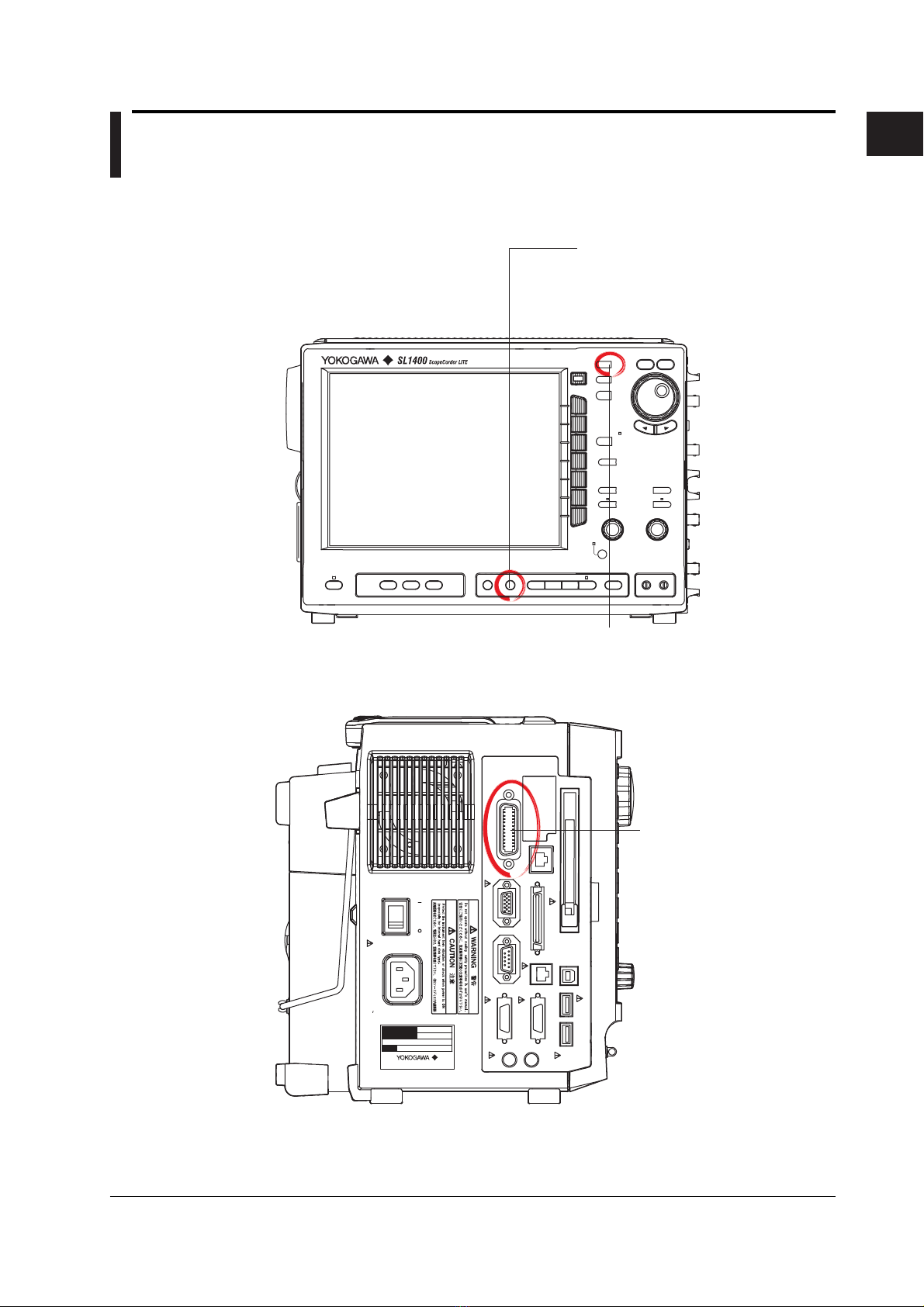
1.1 Names of the Parts and their Function .......................................................................... 1-1
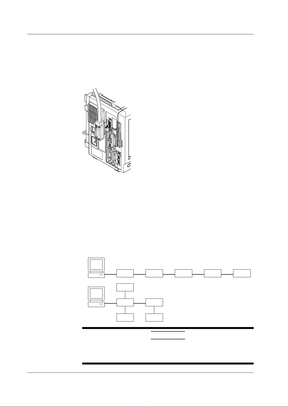
1.2 Connection via the GP-IB Interface ............................................................................... 1-2
1.3 GP-IB Interface Functions ............................................................................................. 1-3
1.4 GP-IB Interface Specifications ....................................................................................... 1-4
1.5 Setting up this Instrument (GP-IB) ................................................................................. 1-5
1.6 Response to Interface Messages .................................................................................. 1-6
Chapter 2 Overview of the Serial (RS-232) Interface
2.1 Names of the Parts and their Function .......................................................................... 2-1
2.2 Serial (RS-232) Interface Functions and Specifications ................................................ 2-2
2.3 Connection via the Serial (RS-232) Interface ................................................................ 2-3
2.4 Handshaking .................................................................................................................. 2-5
2.5 Matching the Data Format ............................................................................................. 2-7
2.6 Setting up this Instrument (Serial) ................................................................................. 2-8
Chapter 3 USB Interface
3.1 Names of the Parts and their Function .......................................................................... 3-1
3.2 USB Interface Functions and Specifications.................................................................. 3-2
3.3 Connection via the USB Interface .................................................................................. 3-3
3.4 Setting up this Instrument (USB) ................................................................................... 3-4
Chapter 4 Network Interface (Option)
4.1 Names of the Parts and their Function .......................................................................... 4-1
4.2 Network Interface Functions and Specifications ............................................................ 4-2
4.3 Connection via the Network Interface ............................................................................ 4-4
4.4 Setting up this Instrument (Network) ............................................................................. 4-5
Chapter 5 Before Programming
5.1 Messages ...................................................................................................................... 5-1
5.2 Commands .................................................................................................................... 5-3
5.3 Response....................................................................................................................... 5-4
5.4 Data ............................................................................................................................... 5-5
5.5 Synchronization with the Controller ............................................................................... 5-7
Chapter 6 Commands
6.1 A List of Commands ...................................................................................................... 6-1
6.2 ACQuire Group ............................................................................................................ 6-18
6.3 ASETup Group ............................................................................................................. 6-20
6.4 CALibrate Group .......................................................................................................... 6-21
6.5 CHANnel Group ........................................................................................................... 6-22
6.6 CLEar Group................................................................................................................ 6-44
6.7 COMMunicate Group ................................................................................................... 6-45
6.8 CURSor Group ............................................................................................................ 6-47
6.9 DISPlay Group ............................................................................................................. 6-56
6.10 FILE Group ..................................................................................................................6-61
6.11 HCOPy Group.............................................................................................................. 6-67
6.12 HISTory Group ............................................................................................................. 6-77

v
IM 701240-17E
6.13 IMAGe Group............................................................................................................... 6-82
6.14 INITialize Group ........................................................................................................... 6-84
6.15 LOGic Group................................................................................................................ 6-85
6.16 LSTart Group ............................................................................................................... 6-87
6.17 MATH Group ................................................................................................................ 6-88
6.18 MEASure Group .......................................................................................................... 6-92
6.19 MONitor Group .......................................................................................................... 6-105
6.20 MTRigger Group ........................................................................................................ 6-108
6.21 RECorder Group ........................................................................................................ 6-109
6.22 SNAP Group .............................................................................................................. 6-115
6.23 SSTart Group ............................................................................................................. 6-115
6.24 STARt Group.............................................................................................................. 6-116
6.25 STATus Group ............................................................................................................ 6-116
6.26 STOP Group .............................................................................................................. 6-117
6.27 SYSTem Group .......................................................................................................... 6-118
6.28 TIMebase Group ........................................................................................................ 6-122
6.29 TRIGger Group .......................................................................................................... 6-123
6.30 WAVeform Group ....................................................................................................... 6-140
6.31 XY Group ................................................................................................................... 6-145
6.32 ZOOM Group ............................................................................................................. 6-147
6.33 Common Command Group........................................................................................ 6-151
Chapter 7 Status Report
7.1 Overview of the Status Report....................................................................................... 7-1
7.2 Status Byte .................................................................................................................... 7-2
7.3 Standard Event Register................................................................................................ 7-3
7.4 Extended Event Register ............................................................................................... 7-4
7.5 Output Queue and Error Queue .................................................................................... 7-5
Chapter 8 Sample Program
8.1 Before Programming ...................................................................................................... 8-1
8.2 Image of Sample Program ............................................................................................. 8-2
8.3 Initialize/Error/Execute ................................................................................................... 8-3
8.4 Sets/Queries the Record Time ...................................................................................... 8-6
8.5 Data Output in Word Format (2 bytes) ........................................................................... 8-8
8.6 Sets/Queries Measure Value ....................................................................................... 8-14
Appendix
Appendix 1 ASCII Character Codes ..................................................................................App-1
Appendix 2 Error Messages ..............................................................................................App-2
Appendix 3 Overview of IEEE 488.2-1992 ........................................................................App-4
Index
Contents
1
2
3
4
5
6
7
8
App
Index

1-1
IM 701240-17E
1
Overview of the GP-IB Interface
Chapter 1 Overview of the GP-IB Interface
1.1 Names of the Parts and their Function
Front Panel
MENU Key (Page 1-5)
Press to enter the communication settings
such as the address and the timeout.
CLEAR TRACE Key
Press to switch from remote mode to
local mode which allows key operation.
However, this is not possible if Local
Lockout has been set by the controller
(refer to page 1-6.)
MENU
DISPLAY
MODE
RECORD
FILEZOOMCURSOR
MEASURE
HISTORY
START/
STOP
CHART
SPEED
CH
ALL CH
RANGE
FINE
POSITION
FINE
RANGE POSITION
TRID'D
MANUALTRIG
RESET SELECT
IMAGE
SAVE
PRINTFEED
Side Panel
GP-IB Connector
This connector is for connecting
the controller (such as a PC) with
the GP-IB cable. For information
on how to connect the GP-IB
cable, refer to the following page.
GP-IB (IEEE488)
ON
100-120V/200-240V AC
300VA MAX 50/60Hz
POWER
100BASE-TX
VIDEO OUT (SVGA)
SERIAL (RS-232)
USB
USB PERIPHERAL
LOGIC B
TRIG OUT/
EXT CLK IN
LINK
ACT
SCSI
LOGIC A
OFF
START/
STOP
TRIG IN
Made in Japan
MODEL
SUFFIX
NO.
1.1 Names of the Parts and their Function

1-2 IM 701240-17E
1.2 Connection via the GP-IB Interface
GP-IB Cable
The GP-IB connector on the side panel of the SL1400 is a 24-pin connector that conforms to
IEEE Standard 488-1978. Use a GP-IB cable that also conforms to IEEE Standard 488-1978.
Connection Method
Connect the GP-IB cable as shown below.
Connection Precautions
• Be sure to tighten the screws on the GP-IB cable connector firmly.
•The instrument can be connected to more than one item of equipment (e.g. a
personal computer) if more than one GP-IB cable is used. However, it is not possible
to connect more than 15 items of equipment (including the controller) to a single bus.
•If you connect the instrument to more than one item of equipment, make sure that a
different address is used for each item.
• Each connecting cable must be 2 m or less in length.
•The total length of all the cables must not exceed 20 m.
•While communications are in progress, more than two-thirds of the connected
equipment items must be turned ON.
•When connecting more than one item of equipment, connect them so that the connection
route forms a star or linear configuration. Loop or parallel wiring is not allowed.
CAUTION
Be sure to switch off power to both your PC and the oscilloscope before
connecting or disconnecting cables. Failure to switch power off may cause
internal circuit failure or improper operation.
1.2 Connection via the GP-IB Interface

1-3
IM 701240-17E
1
Overview of the GP-IB Interface
1.3 GP-IB Interface Functions
GP-IB Interface Functions
Listener Function
•Allows you to make the settings which you can make using the panel keys on the
instrument, except for the power ON/OFF and GP-IB communications settings.
•Receives commands from a controller requesting output of set-up and waveform data.
•Also receives status report commands
Talker Function
Outputs set-up and waveform data.
Note
The listen-only, talk-only and controller functions are not available on this instrument.
Switching between Remote and Local Mode
When Switched from Local to Remote Mode
Remote mode is activated when a REN (Remote Enable) message is received from a
controller while local mode is active.
•REMOTE is displayed on the upper right of the screen.
•All front panel keys except CLEAR TRACE can no longer be operated any more.
•Settings entered in local mode are retained.
When Switched from Remote to Local Mode
Pressing CLEAR TRACE in remote mode puts the instrument in local mode. However,
this is not possible if Local Lockout has been set by the controller (page 1-7).
• The REMOTE indicator on the upper right of the screen is turned off.
•All front panel keys are operative.
•Settings entered in remote mode are retained.
Note
The GP-IB interface cannot be used simultaneously with other communications interfaces
(serial (RS-232), USB, or network).
1.3 GP-IB Interface Functions

1-4 IM 701240-17E
1.4 GP-IB Interface Specifications
GP-IB Interface Specifications
Electrical and Mechanical Specifications: Conforms to IEEE Standard 488-1978.
Interface Functions: Refer to the table below.
Protocol: Conforms to IEEE Standard 488.2-1992.
Code: ISO (ASCII) code
Mode: Addressable mode
Address Setting: Addresses 0 to 30 can be selected from the
GP-IB setting screen in the remote control
menu.
Remote Mode Clear: Remote mode can be cleared by pressing
CLEAR TRACE key. However, this is not
possible if Local Lockout has been set by the
controller.
Interface Functions
Function Subset Name Description
Source Handshaking SH1 Full source handshaking capability
Acceptor Handshaking AH1 Full acceptor handshaking capability
Talker T6 Basic talker capability, serial polling, untalk
on MLA (My Listen Address), no talk-only
capability
Listener L4 Basic listener capability, unlisten on MTA
(My Talk Address), no listen-only capability
Service Request SR1 Full service request capability
Remote Local RL1 Full remote/local capability
Parallel Poll PP0 No parallel polling capability
Device Clear DC1 Full device clear capability
Device Trigger DT0 No device trigger capability
Controller C0 No controller function
Electrical Characteristic E1 Open collector
Data Transfer Rate
The table below shows approximate response times for output of waveform data,
assuming the following configuration.
Model: 701240
Controller: EPSON Endeavor VZ-6000 (Pentium III, 733 MHz)
GP-IB Board: NI AT-GPIB/TNT(PNP)
Programming Language: Visual C++
Data Volume Byte Format Word Format ASCII Format
1000 approx. 64 ms approx. 68 ms approx. 530 ms
10000 approx. 114 ms approx. 160 ms approx. 5.3 s
100000 approx. 673 ms approx. 1.2 s approx. 52.8 s
1000000 approx. 6.5 s approx. 11.8 s approx. 530 s
1.4 GP-IB Interface Specifications

1-5
IM 701240-17E
1
Overview of the GP-IB Interface
1.5 Setting up this Instrument (GP-IB)
Operating Procedure
Selecting the Communication Interface
1. Press MENU.
2. Press the Next 1/2 soft key.
3. Press the Remote Cntl soft key.
4. Press the Device soft key to select GP-IB.
Note
Only the communications interfaces selected under Device are available. If commands are
sent using an unselected communications interface, the command will not be received.
Setting the Address
4. Turn the jog shuttle to set the desired address.
Explanation
When you make settings which can be made using the front panel keys of the instrument
or when you output setup data or waveform data using the controller, the following
settings must be made.
Setting the Address
This function allows you to set the instrument’s address for addressable mode within the
range of 0 to 30. Each item of equipment connected via a GP-IB interface has its own
address, by which it can be identified. Care must be taken to ensure that all
interconnected devices are assigned unique addresses.
Note
Do not change the address while the GP-IB interface is being used by the controller.
1.5 Setting up this Instrument (GP-IB)

1-6 IM 701240-17E
1.6 Response to Interface Messages
Response to Interface Messages
Response to a Uni-line Message
IFC(Interface Clear)
Clears the talker and listener. Stops output if data is being output.
REN(Remote Enable)
Switches between remote and local modes.
IDY (Identify) is not supported.
Response to a Multi-Line Message (Address Command)
GTL(Go To Local)
Switches to local mode.
SDC(Selected Device Clear)
Clears the program message (command) which is currently being output. Also clears the
output queue (page 7-5).
*OPC and *OPC? will be disabled if they are currently being executed.
*WAI and :COMMunicate:WAIT will be stopped immediately.
PPC (Parallel Poll Configure), GET (Group Execute Trigger) and TCT (Take Control) are
not supported.
Response to a Multi-Line Message (Universal Command)
LLO(Local Lockout)
Invalidates SHIFT+CLEAR on the front panel to disable switching to local mode.
DCL(Device Clear)
Same as SDC.
SPE(Serial Poll Enable)
Sets the talker function to serial poll mode for all equipment connected to the
communications bus. The controller performs polling on equipment sequentially.
SPD(Serial Poll Disable)
Clears serial poll mode as the talker function for all equipment connected to the
communications bus.
PPU (Parallel Poll Unconfigure) is not supported.
What is an Interface Message?
An interface message is also called an interface command or bus command, and is
issued by the controller. Interface messages are classified as follows.
Uni-Line Messages
Messages are transferred through a single control line. The following three types of uni-
line message are available.
IFC (InterFace Clear)
REN (Remote ENable)
IDY (IDentifY)
1.6 Response to Interface Messages

1-7
IM 701240-17E
1
Overview of the GP-IB Interface
Multi-Line Message
Eight data lines are used to transmit a message. Multi-line messages are classified as
follows.
Address Commands
Valid when the equipment is designated as a listener or a talker. The following five
address commands are available.
•Commands valid for equipment designated as a listener;
GTL (Go To Local)
SDC (Selected Device Clear)
PPC (Parallel Poll Configure)
GET (Group Execute Trigger)
•Command valid for equipment designated as a talker;
TCT (Take ConTrol)
Universal Commands
Valid for any item of equipment, irrespective of whether the item is designated as a
listener or a talker. The following five universal commands are available.
LLO (Local LockOut)
DCL (Device CLear)
PPU(Parallel Poll Unconfigure)
SPE (Serial Poll Enable)
SPD (Serial Poll Disable)
In addition to the above commands, a listener address, talker address on secondary
command can be sent in an interface message.
Interface Messages
Uni-Line
Messages Address
Command Universal
Command
◆IFC
◆REN
IDY ◆GTL
◆SDC
PPC
GET
TCT
◆LLO
◆DCL
PPU
◆SPE
◆SPD
Listener
Address Talker
Address Secondary
Command
Multi-Line Messages
Messages marked with a “◆” are interface messages supported by the SL1400.
Note
Differences between SDC and DCL
The SDC command is an address command and requires that both the talker and listener be
designated; however DCL is a universal command and does not require that the talker and
listener be designated. Therefore, SDC is used for particular items of equipment, while DCL
can be used for any equipment connected to the communications bus.
1.6 Response to Interface Messages

2-1
IM 701240-17E
Overview of the Serial (RS-232) Interface (Option)
2
Chapter 2 Overview of the Serial (RS-232) Interface
2.1 Names of the Parts and their Function
Front Panel
MENU Key (Page 2-8)
Press to enter the communication settings
such as the baud rate , data format, and
the handshaking method.
CLEAR TRACE Key
Press to switch from remote mode to
local mode which allows key operation.
However, this is not possible if Local
Lockout has been set by the controller
(refer to page 2-2.)
MENU
DISPLAY
MODE
RECORD
FILEZOOMCURSOR
MEASURE
HISTORY
START/
STOP
CHART
SPEED
CH
ALL CH
RANGE
FINE
POSITION
FINE
RANGE POSITION
TRID'D
MANUALTRIG
RESET SELECT
IMAGE
SAVE
PRINTFEED
Side Panel
SERIAL (RS-232) Connector
This connector is for connecting the
controller (such as a PC) with the RS-
232 cable. For information on how to
connect the RS-232 cable, refer to
page 2-3.
GP-IB (IEEE488)
ON
100-120V/200-240V AC
300VA MAX 50/60Hz
POWER
100BASE-TX
VIDEO OUT (SVGA)
SERIAL (RS-232)
USB
USB PERIPHERAL
LOGIC B
TRIG OUT/
EXT CLK IN
LINK
ACT
SCSI
LOGIC A
OFF
START/
STOP
TRIG IN
Made in Japan
MODEL
SUFFIX
NO.
2.1 Names of the Parts and their Function

2-2 IM 701240-17E
2.2 Serial (RS-232) Interface Functions and Specifications
Receiving Function
It is possible to make the same settings via the serial (RS-232) interface as can be made
using the front panel keys.
Measured/computed data, setup data and error codes can be received.
Sending Function
Measured/computed data can be output.
Setup data and the status byte can be output.
Error codes which have occurred can be output.
Serial (RS-232) Interface Specifications
Electrical Characteristics: Conforms to EIA 574 Standard (EIA-232 (RS-232) Standard
for 9-pin)
Connection: Point-to-point
Communications: Full-duplex
Synchronization: Start-stop system
Baud Rate: 1200, 2400, 4800, 9600, 19200, 38400, 57600
Start Bit: 1 bit (fixed)
Data Length: 7 or 8 bits
Parity: Even, odd or no parity
Stop Bit: 1 or 2 bits
Connector: DELC-J9PAF-13L6 (JAE or equivalent)
Hardware Handshaking: User can select whether CA or CB signals will always be
True, or will be used for control.
Software Handshaking: User can control both transmission and reception using X-on
and X-off signals. (X-on (ASCII 11H), X-off (ASCII 13H))
Receive Buffer Size: 256 bytes
Switching between Remote and Local Mode
When Switched from Local to Remote Mode
Remote mode is activated when the ":COMMunicate:REMote ON" command is
received from a controller while local mode is active.
•REMOTE is displayed on the upper right of the screen.
•All front panel keys except CLEAR TRACE can no longer be operated any more.
•Settings entered in local mode are retained.
When Switched from Remote to Local Mode
Pressing CLEAR TRACE in remote mode puts the instrument in local mode. However,
this is not possible of Local Lockout (when the ":COMMunicate:LOCKout ON"
command is received) has been set by the controller.
Local mode is activated when the ":COMMunicate:REMote OFF" command
regardless of Local Lockout.
• The REMOTE indicator on the upper right of the screen is turned off.
•All front panel keys are operative.
•Settings entered in remote mode are retained.
Note
The serial interface cannot be used simultaneously with other communications interface (GP-
IB, USB, or network).
2.2 Serial (RS-232) Interface Functions and Specifications

2-3
IM 701240-17E
Overview of the Serial (RS-232) Interface (Option)
2
2.3 Connection via the Serial (RS-232) Interface
When connecting this instrument to a computer, make sure that the handshaking
method, data transmission rate and data format selected for the instrument match those
selected for the computer.
For details, refer to the following pages. Also make sure that the correct interface cable
is used.
Connector and Signal Names
2
1
3
4
5
6
7
8
9
2 RD (Received Data): Data received from PC.
Signal direction...Input.
3SD (Send Data): Data transmitted to a PC.
Signal direction...Output.
5SG (Signal Ground): Ground for signals.
7RS (Request to Send): Signal used for handshaking when receiving data from a
PC.
Signal direction...Output.
8CS (Clear to Send): Signal used for handshaking when transmitting data to a
PC.
Signal direction...Input.
*Pin Nos. 1, 4, 6, and 9 are not used.
9-25 Pin Connector
58723
(2) (3) (4) (5) (7)
The number between brackets refer to the pin No. of the 25-pin connector.
Signal Direction
The figure below shows the direction of the signals used by the serial (RS-232) interface.
Computer This
Instrument
RS [Request to Send]
SD [Send Data]
RD [Receive Data] 2
3
8
7
CS [Clear to Send]
2.3 Connection via the Serial (RS-232) Interface

2-4 IM 701240-17E
Table of RS-232 Standard Signals and their JIS and CCITT Abbreviations
Pin No.
(9-Pin Connector)
Abbreviation
RS-232 Description
CCITT JIS
5
3
2
8
7
AB (GND)
BA (TXD)
BB (RXD)
CB (CTS)
CA (RTS)
102 SG
103
104
106
105
SD
RD
CS
RS
Signal ground
Transmitted data
Request to send
Received data
Clear to send
Signal Line Connection Examples
The pin numbers shown are that of 9-pin connectors.
In general, use a cross cable.
SD
RD
RS
CS
SG
SD
RD
RS
SG
• OFF-OFF / XON-XON
PC SL1400
SD
RD
RS
CS
SG
SD
RD
RS
SG
• CTS-RTS(CS-RS)
PC SL1400
CS CS
2
3
8
7
5
2
3
8
7
5
2
3
8
7
5
2
3
8
7
5
2.3 Connection via the Serial (RS-232) Interface

2-5
IM 701240-17E
Overview of the Serial (RS-232) Interface (Option)
2
2.4 Handshaking
To use an serial (RS-232) interface for transferring data between this instrument and a
computer, it is necessary to use certain procedures by mutual agreement to ensure the
proper transfer of data. These procedures are called “handshaking.” Various
handshaking systems are available depending on the computer to be used; the same
handshaking system must be used for both the computer and this instrument.
This instrument allows you to choose any handshaking mode from the following three
modes.
Data Sending Control (Control Method
When Sending Data to a Computer) Data Receiving Control
(Control Method
When Receiving Data from a Computer)
Software
Handshake Software
Handshake
Handshake Format Descriptions→
NO-NO
XON-XON
CTS-RTS
Handshake
Method Sending stops
when X-off is
received, and
sending is
resumed
when X-on is
received.
Sending stops
when CB(CTS) is
False, and sending
is resumed when
CB is True.
No
handshake
No
handshake
X-off is sent
when received
data buffer
becomes 3/4-
full, and X-on is
sent when the
received data
buffer is only
1/4-full.
CA (RTS) is set to
False when
received data buffer
is only 3/4-full, and
is set to True when
received data buffer
is only 1/4-full.
Hardware
Handshake Hardware
Handshake
OFF-OFF
XON-XON
CS-RS
The Menu of
this Instrument
OFF-OFF
Transmission Data Control
There is no handshake status between the instrument and PC. The X-OFF and X-ON
signal from the PC is processed as data, and the CS signal is ignored.
Reception Data Control
There is no handshake status between the recorder and PC. When the recorder
reception buffer becomes full, the excess data is discarded. RS = True (fixed).
XON-XON
Transmission Data Control
A software handshake status is established between the instrument and PC. The
instrument will stop a data transmission when an X-OFF signal is received from the PC,
and will resume transmission when the next X-ON signal is received. A CS signal from
the PC is ignored.
Reception Data Control
A software handshake status is established between the instrument and PC. When the
instruments reception buffer vacancy reaches 64 bytes, the X-OFF signal will be sent to
the PC. When the reception buffer vacancy reaches 192 bytes, the X-ON signal will be
sent. RS = True (fixed).
2.4 Handshaking

2-6 IM 701240-17E
CS-RS
Transmission Data Control
A software handshake status is established between the instrument and host computer.
The instrument will stop a data transmission if a “CS = False” status is established, and
will resume the transmission when a “CS = True” status is established. The X-OFF and
X-ON signals from the host computer are processed as data.
Reception Data Control
A hardware handshake status is established between the instrument and host computer.
When the instruments reception buffer vacancy reaches 64 bytes, an “RS=False” status
will be established. When the reception buffer vacancy reaches 192 bytes, an
“RS=True” status will be established.
Precautions Regarding Data Receiving Control
When handshaking is used to control the reception of data, data may still be sent from
the computer even if the free space in the receive buffer drops below 64 bytes. In this
case, after the receive buffer becomes full, the excess data will be lost, whether
handshaking is in effect or not. Data storage to the buffer will begin again when there is
free space in the buffer.
256 bytes
Used Free, 64 bytes
When handshaking is in use,
reception of data will stop when the
free space in the buffer drops to 64
bytes since data cannot be passed to
the main program fast enough to
keep up with the transmission.
Used Free, 192 bytes
After reception of data stops, data
continues to be passed to the internal
program. Reception of data starts
again when the free space in the
buffer increases to 192 bytes.
Used
Whether handshaking is in use or not,
if the buffer becomes full, any
additional data received is no longer
stored and is lost.
Data Receiving Control Using Handshaking
Note
It is necessary to create a host computer program which prevents the buffers of both the
instrument and the computer from becoming full.
2.4 Handshaking

2-7
IM 701240-17E
Overview of the Serial (RS-232) Interface (Option)
2
2.5 Matching the Data Format
The serial (RS-232) interface of this instrument performs communications using start-
stop synchronization, In start-stop synchronization, one character is transmitted at a
time. Each character consists of a start bit, data bits, a parity bit, and a stop bit. Refer to
the figure below.
Data Bit
(7 or 8 bits)
1 character
Stop Bit
1
1 or 2 Bits
2
Parity Bit
Even, Odd, or None
Start Bit
Circuit Idle State
Level returns to idle
state (dotted line)
until the start bit of
the next item of data
(solid line).
2.5 Matching the Data Format
Other manuals for SL1400 ScopeCorder LITE
2
Table of contents
Other YOKOGAWA Voice Recorder manuals

YOKOGAWA
YOKOGAWA DR231 User manual

YOKOGAWA
YOKOGAWA GX60 User manual

YOKOGAWA
YOKOGAWA DR130 User manual

YOKOGAWA
YOKOGAWA ScopeCorder DL750 User manual

YOKOGAWA
YOKOGAWA SMARTDAC+ GX10 User manual

YOKOGAWA
YOKOGAWA FX1000 User manual

YOKOGAWA
YOKOGAWA MuR10000 User manual

YOKOGAWA
YOKOGAWA ScopeCorder DL350 User manual

YOKOGAWA
YOKOGAWA SMARTDAC+ GX User manual

YOKOGAWA
YOKOGAWA SMARTDAC+ GX10 User manual