York challenger dominator 51071 User manual

Owner’s Manual
Challenger Dominator Treadmill
Model No. 51071
YORK FITNESS U.K. LTD.
YORK WAY, DAVENTRY, NORTHANTS,
YORK BARBELL (AUST) PTY. LTD.
LOT 2, SWAFFHAM ROAD, MINTO,
OPERATING INTSTRUCTIONS
P1
12
11
10
9
8
7
6
5
4
3
2
1
2
4
6
8
10
12
14
16
18
P2
P1
P2
P2
P4
P3
P3
HEART RATE CHART
ChallengerDominatorTreadmill_Ins1 1 11/23/08 6:16:04 PM

Thank you for
purchasing a
YORK FITNESS
product.
You have chosen a high quality, safe and innovative piece
of equipment as your training partner and we are certain
it will keep you motivated on the way to achieving your
personal tness goal.
Please take the time to read this owner’s manual as it
will help you to get the most out of your new tness
equipment. For more information visit:
www.yorktness.com
PLEASE READ THIS INSTRUCTION MANUAL BEFORE
YOU BEGIN ASSEMBLY. GREAT CARE HAS BEEN
TAKEN TO DESIGN THESE INSTRUCTIONS AND
FOLLOWING THEM WILL HELP YOU WITH QUICKER
ASSEMBLY AND MINIMIZE THE RISK OF INJURY.
.y
PLEASE
YOU BE
TAKEN
FOLLOW
ASSEMB
ChallengerDominatorTreadmill_Ins2 2 11/23/08 6:16:10 PM

CHALLENGER Dominator Treadmill | OWNER’S MANUAL • 3
Contents
Safety Information ................................................................ 04
Customer Support ................................................................ 05
Assembly Instructions ............................................... 06 - 09
User Instructions .......................................................... 10 - 15
• Operating Instructions ..................................... 10 - 11
• Computer Instructions .............................................. 12
• Workout programs ............................................. 13 - 14
• Fitness Guide ................................................................... 15
Troubleshooting ..................................................................... 16
Warranty ..................................................................................... 17
Part List .............................................................................. 18 - 19
ChallengerDominatorTreadmill_Ins3 3 11/23/08 6:16:10 PM

4 • CHALLENGER Dominator Treadmill | OWNER’S MANUAL
Important safety instructions
THIS LIST IS NOT EXHAUSTIVE - You are responsible for
your own safety.
Assemble and operate the equipment on a solid and
level surface.
Always ensure that the equipment has adequate
space on each side. (Please see product information)
Examine this equipment regularly for wear and tear.
Always check that any pins / xings are tight and
secure before use and / or after adjustment. Replace
defective components immediately, and’or keep the
equipment out of use until it is repaired.
Use only the adjustment settings as described in
the instructions. Always use the correct adjustment
pin/xings.
Never use the equipment in anyo other manner other
than the ways explained in these instructions and/or
any wall chart supplied.
Do not use any accessories that aren’t specically
recommended by the manufacturer. These might
cause injuries or cause the unit to fail.
Keep hands away from moving parts.
Wear proper workout clothing: Do not wear loose
clothing.
Do not wear shoes with leather soles or high heels. Tie
all long hair back.
Remove all personal jewelry before exercising.
Care should be taken when mounting and
dismounting the unit.
Injuries to health may result from incorrect or
excessive training.
If you feel any pain or abnormal symptoms, STOP
YOUR WORKOUT IMMEDIATELY. Consult your
physician immediately.
After eating, allow 1-2 hours before exercising as this
will help to prevent muscle strain.
This is not a toy! Children should not be allowed on,
or around the equipment when it is not in use.
If Children are allowed to use the equipment, their
mental and physical development and above all their
temperament should be taken into account. They
should be controlled and instructed by an adult in the
correct use of the equipment.
•
•
•
•
•
•
•
•
•
•
•
•
•
•
•
•
•
•
Additional Information:
This appliacnce has electical components.
This appliance must be earthed.
Keep all electical companents away from water.
Do not use water bottle in areas where high humidity
may cause condensation to drip onto the treadmill.
Unplug the power cable before maintenance.
Stop treadmill before folding.
TAKE CARE TO PROTECT CARPETS AND FLOOR in case
of leakages.
This product contains moving parts which have been
greased / lubricated and could leak.
The treadmill running mat will not stop immediately
if any object becomes caught in the mat or rollers - IN
AN EMERGENCY: Pull the safety key cord to remove
the safety key.
This product is provided with a safety key. The
treadmill will not operate without the safety key
inserted. The safety key should be attached to the
user via the cord and clip. If for any reason the
user falls, the cord will pull the safety key from the
treadmill and the treadmill will begin to decelerate.
In an emergency, take hold of the handrails and place
your feet on the side platforms provided. Once you
are stable pull out the safety key. The treadmill will
begin to decelerate until it stops.
Never overload the equipment - the maximum user
load of this equipment is 275lb (125kg).
Safety Standards
This product meets the requirements of the EU’s EMC
and Low Voltage directives and ISO 20957 parts 1 and 6.
Therefore the product carries the following marks:
This product is not suitable for therapeutic
purposes.
Protect the environment. Do not dispose
this product with household waste. Check
your local authority for recycling advice and
facilities.
•
•
•
•
•
•
•
•
•
•
•
Safety Information
ChallengerDominatorTreadmill_Ins4 4 11/23/08 6:16:10 PM

CHALLENGER Dominator Treadmill | OWNER’S MANUAL • 5
CARE & MAINTENANCE
PROTECT THE ENVIRONMENT. DO NOT DISPOSE
THIS PRODUCT WITH HOUSEHOLD WASTE. CHECK
YOUR LOCAL AUTHORITY FOR RECYCLING ADVICE
AND FACILITIES EUROPE ONLY.
Always place the equipment in a dry environment.
Use a warm, damp cloth to keep the product clean.
No wet cleaning of electrical components. Unplug
before performing any maintenance.
The safety level of the equipment can be maintained
only if it is regularly examined for damage and wear.
This includes any ropes, pulleys, nuts, bolts, moving
parts, bushes, chains, wheels, bearings & connection
points etc.
Ensure that you inspect the product regularly - at
least once a week is recommended.
Ensure that all xings are tight before use.
Always replace damaged / worn components with
original parts from the manufacturers.
CUSTOMER SUPPORT
Should you require any assistance regarding this product
please gather the following information, and then contact
us using the details below.
Serial no. - this can be found on the sticker located
as indicated. For future reference, please write down
your serial number in the space below.
Original purchase date.
Place of purchase.
Information about the place and conditions of use.
Precise description of the issue / defect.
Serial No:
•
•
•
•
•
•
•
•
•
•
•
•
CONTACT US
ENGLAND
YORK FITNESS U.K. LTD.
York Way, Daventry, Northants, NN11 4YB, England
Tel: (01327) 701800
Help desk Tel: (01327) 701824
Fax: (01327) 706704
Email: helpdesk@yorktness.co.uk
AUSTRALIA
YORK BARBELL AUST PTY. LTD.
Unit 1, Lot 2, Swaham Road, Minto, N.S.W. 2566, Australia
Tel: (02) 9603 8444
YORK® Assist: 1800 730 149
Fax: (02) 9603 8555
Email: service@yorktness.com.au
OTHER LOCATIONS
Please see website - www.yorktness.com
Use only on a level surface
Not suitable for therapeutic purpos e
ChallengerDominatorTreadmill_Ins5 5 11/23/08 6:16:11 PM

6 • CHALLENGER Dominator Treadmill | OWNER’S MANUAL
Assembly Instruction
INTRODUCTION
YORK® Dominator has been designed and constructed
to provide trouble free usage and enjoyable exercise.
You can greatly improve your understanding of the
benets of exercising by carefully reading the instructions
given in this manual. Please familiarize yourself with the
maintenance advice provided for you.
Specications
Power supply: AC 230V, 50Hz
Speed Control: Push button
Elevation: Power incline 0 ~ 12 level
Speed range: 0.8 ~ 18KPH
•
•
•
•
OPERATINGINTSTRUCTIONS
P1
12
11
10
9
8
7
6
5
4
3
2
1
2
4
6
8
10
12
14
16
18
P2
P1
P2
P2
P4
P3
P3
HEART RATE CHART
MAT ADJUSTING BOLTS
MAIN FRAME
FOUR WHEELS
TRANSPORTATION
COMPUTER PANEL
SPEED ADJUSTMENT SWITCH
INCLINE
ADJUSTMENT SWITCH
RUNNING MAT
HANDLE BAR POST
FOLD TREADMILL UP
AND STAND
VERTICALLY AGAINST A
WALL FOR STORAGE
HAND PULSE SENSORS
MAGAZINE RACK
ChallengerDominatorTreadmill_Ins6 6 11/23/08 6:16:16 PM

CHALLENGER Dominator Treadmill | OWNER’S MANUAL • 7
Step 1
Ask someone to help you remove all the parts
and packaging materials on the top of your YORK®
Dominator from the carton and place them on the
oor carefully.
NOTE: Do not lift the treadmill out of the carton from
the motor end as your ngers may get squashed!
A.
Step 2
Fold the handle bar post assembly up gently until the
xing holes on handle bar post align to the holes on
base brackets as shown.
Secure the handle bar posts to the base brackets by
using four allen head bolts and at washers.
NOTE: Do not fully tighten the bolt until the
computer console has been secured.
A.
B.
51071-85 x 4
51071-84 x 4
ChallengerDominatorTreadmill_Ins7 7 11/23/08 6:16:17 PM

8 • CHALLENGER Dominator Treadmill | OWNER’S MANUAL
Assembly Instructions
Step 3
Rotate the computer assembly until the xing holes
on the handle bar bracket align to the holes on
handle bar posts as shown.
Secure the handle bar bracket to the handle bar posts
by using two allen head bolts and two at washers.
A.
B.
Step 4
Attach the right handle bar post cover to the right
base frame and secure, using three tapping screws.
Attach the left handle bar post cover to the left base
frame and secure, using three tapping screws as
shown.
A.
B.
51071-85 x 2
51071-84 x 2
51071-89 x 6
ChallengerDominatorTreadmill_Ins8 8 11/23/08 6:16:18 PM

CHALLENGER Dominator Treadmill | OWNER’S MANUAL • 9
Step 5
Attach the magazine rack to the console base and
secure, using three tapping screws as shown.
NOW tighten all the bolts that you have tted.
A.
B.
Step 6
Fold the main frame up gently until the main frame
is locked in position by the locking device lever and
stand it in the carton base.
Ask someone to help you hold the treadmill on each
side and lift it out from the carton base carefully.
RECHECK
Recheck that all of the bolts are tightened securely for
your safety and comfort.
Plug the power cable into a suitable AC outlet
(220~240 Volt 50Hz).
Before you use the treadmill for the rst time, turn on
the power switch. Connect the magnetic safety key
and then allow the treadmill to run for 10 minutes
without anyone on the treadmill. Check that the mat
is tightened properly and runs smoothly.
A.
B.
1.
2.
3.
51071-101x3
ChallengerDominatorTreadmill_Ins9 9 11/23/08 6:16:18 PM

10 • CHALLENGER Dominator Treadmill | OWNER’S MANUAL
The following procedure has been proven to be the
safest and easiest method of mounting the treadmill.
For your protection, carefully read and follow these
simple steps:
Be sure the treadmill is positioned on a at, level
surface.
Make sure the magnetic safety key is not attached
then plug in the treadmill power cable to a suitable
power socket and switch on at the socket.
Turn on the treadmill power switch which is located
near where the power cable attaches to the treadmill.
Straddle the running mat with your feet rmly
planted on the right and left staging platforms. Stand
close enough so you can extend your arms to touch
all the buttons on the console. CAUTION: Do not
stand on the mat yet.
Insert the safety key.
Press “START” key, the treadmill will start at the lowest
speed.
STARTING YOUR EXERCISE
Stand on the running mat.
Once you have selected your workout, the treadmill
will slowly increase it’s speed to the desired levels.
Continue to grip the handles until you are walking /
running normally.
After gaining stability and condence, release your
grip on the handrails and let your arms swing freely
and naturally at your side.
NOTE: WALKING STRAIGHT ON THE TREADMILL IS
AIDED BY FOCUSING ON A STATIONARY OBJECT
ACROSS THE ROOM IN FRONT OF YOU. WALK AS IF
YOU WERE APPROACHING THAT OBJECT.
GETTING OFF THE TREADMILL
The following procedure has been proven to be
the safest and easiest method of dismounting the
treadmill. For your protection, carefully read and
follow these simple steps:
Turn treadmill to the lowest speed and incline.
Firmly grip the handles to support yourself.
Remove your trailing foot from the walking platform
and place it on the foot pad on the side of the
treadmill. This is very easy to do because the natural
movement of walking will have shifted your weight
onto the foot that just stepped forward.
Shift your weight to the stationary foot on the foot
pad, and remove the other foot from the walking
1.
2.
3.
4.
5.
6.
1.
2.
3.
4.
1.
2.
3.
4.
platform and place it on the other foot pad. You
should now be in the starting position.
Press “STOP” key to stop the treadmill and disconnect
the safety key then unplug treadmill from the power
outlet when nished.
IN AN EMERGENCY, TAKE HOLD OF THE HANDRAILS
AND PLACE YOUR FEET ON THE SIDE RAILS
PROVIDED, ONCE YOU ARE STABLE, PULL OUT THE
SAFETY KEY. THE TREADMILL WILL THEN BEGIN TO
DECELERATE UNTIL IT STOPS.
MAT ALIGNMENT AND TENSION
The alignment and tension of the mat (walking
surface) has been set prior to shipping. Should
improper tracking of the mat occur (walking surface
moving too far to right or left on the platform) or if
you nd that the mat slips when you get on, these
problems can be corrected as follows:
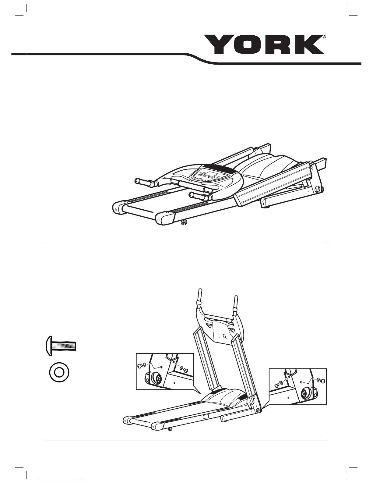
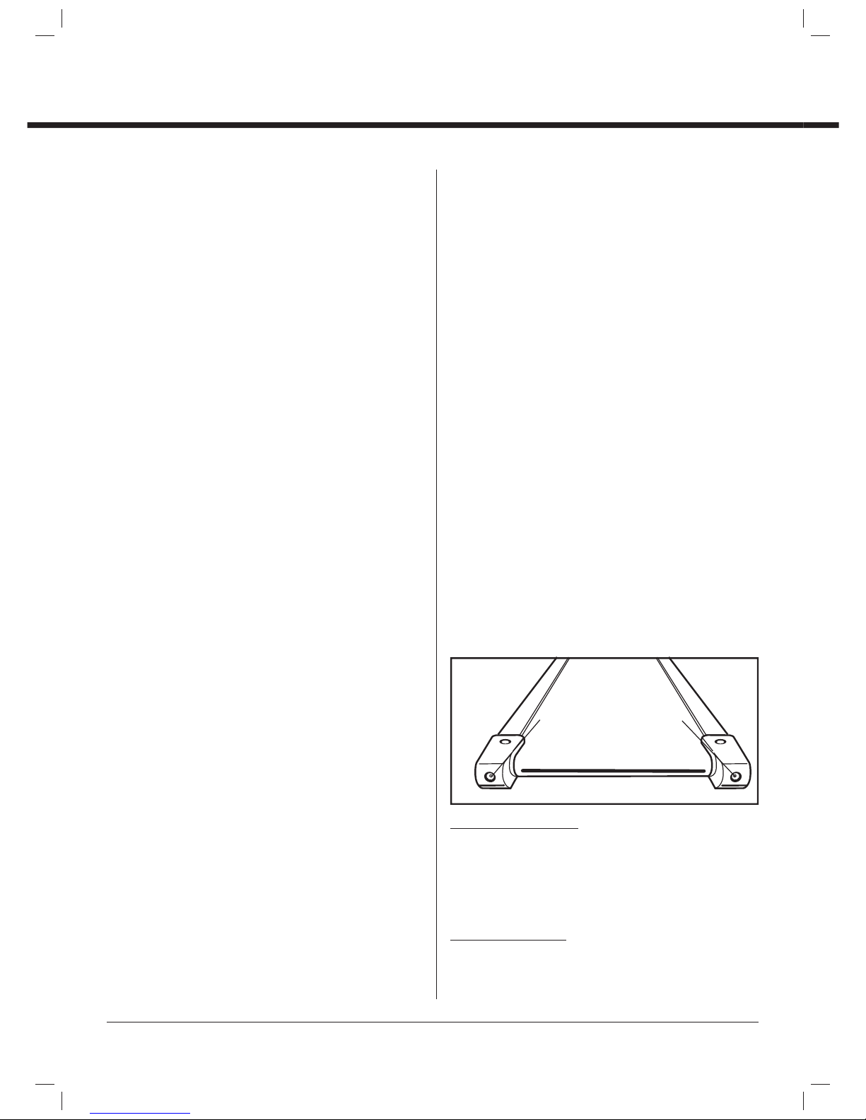
Locate the adjustment screws on the end of the
main frame. CAUTION: Adjust the mat when the
treadmill is running at low speed. Keep others
away from the treadmill.
Connect the safety key and set to the lowest speed.
Allow the mat to run for several minutes and watch
to see if it runs in the center position properly. If the
mat does not run in the center position, carry out the
steps for “MAT MOVES TO LEFT” or “MAT MOVES TO
RIGHT”. Be sure that you adjust by “1/2 turn only each
time”to avoid over correcting.
MAT MOVES TO RIGHT: If your mat tends to move to the
right, then adjust the right screw by turning it a 1/2 turn
clockwise. We recommend adjustments of 1/2 turn only
at a time, then test each time. If your mat continues to
move to the right, simply adjust the left adjustment screw,
by turning 1/2 turn counterclockwise, test after each
adjustment.
MAT MOVES TO LEFT: If your mat tends to move to the
left, then the adjustment of the right screw is necessary
by turning counterclockwise. We recommend adjustments
of 1/2 turn only at a time, then test each time. If the
mat continues to move to the left, simply adjust the left
5.
1.
2.
3.
MAT ADJUSTMENT BOLTS
USE ALLEN KEY TO ADJUST MAT
AS INSTRUCTED BELOW.
Operating Instructions
ChallengerDominatorTreadmill_Ins10 10 11/23/08 6:16:19 PM

CHALLENGER Dominator Treadmill | OWNER’S MANUAL • 11
adjustment screw, by turning 1/2 turn clockwise, then test
each time.
NOTE: For most people, one of your legs is stronger
than the other and the treadmill mat may tend to track
to that side because of the extra pressure exerted by
your stronger leg. If this occurs then either dismount the
treadmill and allow the mat to track back to the middle,
or exert pressure to the side of the mat with the other leg
to track the mat back to the middle. Or adjust the mat to
compensate following the instructions for the mat moves
to the right or left.
MAT TOO LOOSE: If your mat appears to be loose, simply
tighten both screws by an equal amount (1/2 a turn
clockwise at a time) then test.
MAT TOO TIGHT: If it appears tight, simply loosen both
screws by an equal amount (1/2 a turn counter-clockwise
at a time) then test.
MAT STICKY (DOES NOT RUN SMOOTHLY: You may feel
after a period of time (depending on how often you use
the machine) that the mat feels sticky. We recommend
you apply a light covering of Silicone between the mat
and the running board. This procedure may be repeated
as necessary.
WALKING MAT AND DECK LUBRICATION
This treadmill is equipped with a pre-lubricated,
maintenance deck system. The mat / deck friction may
play a major role in the function and life of your treadmill,
this requires periodic lubrication. We recommend a
periodic inspection of the deck. If the deck appears worn,
please contact our service department.
We recommend lubrication of the deck according to
the following timetable:
Less than 3 hours per week - every 8 months.
3-5 hours per week - every 4 months
More than 5 hours per week - every 2 months.
PROPER LUBRICATION APPLICATION
Using a coin to open the top cap covers above the
left and right lubricant bottles. Then put half of
lubrication that is in the spare parts box into the left
and right bottles. After it is done, put the top cap
covers back and tighten them securely.
Start the treadmill and set the speed at the lowest
speed. Let the mat run for about 15 minutes in order
to spread the lubrication on the underneath side of
the running mat properly.
•
•
•
1.
2.
USING THE MAGNETIC SAFETY KEY
IMPORTANT: The treadmill will not work if the magnetic
safety key is not in place. Before starting the treadmill,
attach the key to the computer, then attach the clip on
the other end to your clothing (Above the waist). If this
key is pulled out whilst you are running on the treadmill
then the mat will stop turning.
When the treadmill is not in use you should remove the
safety key and store it somewhere safe, away from the
treadmill. This will prevent any unauthorized use of the
treadmill. Store the safety key in a safe place OUT OF
REACH OF CHILDREN.
ChallengerDominatorTreadmill_Ins11 11 11/23/08 6:16:19 PM

12 • CHALLENGER Dominator Treadmill | OWNER’S MANUAL
Operating Instructions
COMPUTER INSTRUCTIONS
Your computer is ideal for monitoring your performance
and setting yourself targets. You can monitor your
improving condition and cardiovascular tness closely.
KEYS
POWER KEY: Press the “POWER” key to activate the
treadmill, you must press it rst.
START/STOP KEY: Activates the treadmill at the lowest
speed and slowly increases until it reaches your training
speed. Slows the running mat gradually to a complete
stop.
SELECT KEY: Press the “SELECT” key to select the preset
or user program proles. Also displays the elevation
& elevation gain values for three seconds during the
workout.
ENTER KEY: Press the “ENTER” key to conrm your
program selection. Also conrms the speed and incline
target values during the user program setting.
SPEED KEYS: Select the speed from 0.8 ~ 18kp/h. Press
and hold this key continuously for 2 seconds. The speed
values will increase / decrease quickly. Press this key to
select through the preset programs.
INCLINE KEYS: Select the elevation from 0 ~ 12. Press and
hold this key continuously for 2 seconds. The elevation
values will increase / decrease to the desired level quickly.
Press this key to select through the preset programs.
FAN KEY: Switch fan ON / OFF. Press this key to turn on
the fan at low speed, again to middle speed, again to the
high speed then again to turn it o.
RAPID SPEED KEYS: 9 preset buttons for rapid speed:
2km/h, 4km/h, 6km/h, 8km/h, 10km/h, 12km/h, 14km/h,
16km/h, 18km/h. User can press any of these 9 buttons to
start the treadmill to the preset speed automatically.
RAPID ELEVATION KEYS: 12 preset buttons for rapid
elevation: 1, 2, 3, 4, 5, 6, 7, 8, 9, 10, 11, 12. User can press
any of these 12 buttons to start the treadmill to the preset
elevation automatically.
FUNCTION
INCLINE: Current elevation is automatically displayed in
% when the YORK® Dominator treadmill is in use. Enter the
required elevation target by press “UP/DOWN” buttons.
(MAX 12%) WARNING: The treadmill must be on 0%
before you fold.
PULSE: Your current heart rate is shown, when this pulse
function is in use. To obtain a pulse reading you must
have your left and right hands holding the sensors at
the same time. Grip the hand sensors normally (NOT
TOO TIGHT) during exercise and after a few seconds the
computer will display your pulse reading. It is dicult for
the computer to read your pulse rate accurately during
walking or jogging. The user may also need to consult a
doctor before using this equipment.
TIME: Counting commences when the YORK® Dominator
is activated. Enter the required time target by pressing
“UP/DOWN” buttons. (MAX 99:00min)
SPEED: Current speed is displayed in KPH when the
YORK® Dominator is in use. (MAX 999.9km)
DISTANCE: Distance is automatically displayed in KM
when the YORK® Dominator is in use. (MAX 999.9km)
CALORIES: Approximate calories burned is displayed
when the YORK® Dominator is in use. (MAX 9999 Cal.) (This
data is a rough guide for comparison of dierent exercise
sessions. It should not be used for medical purposes.)
ELEVATION GAIN: Total climbing distance displayed in
metres during the current workout. (MAX 9990m) NOTE:
This value will only displayed in Target Elevation Gain
program.
DOT MATRIX: This 8 x 10 dot matrix displays the proles
of the 6 x preset programs & 2 x user programs. This dot
matrix displays a 0.4km running track when selected in
manual, target distance, target calories, target time or
target elevation gain programs.
ChallengerDominatorTreadmill_Ins12 12 11/23/08 6:16:19 PM

CHALLENGER Dominator Treadmill | OWNER’S MANUAL • 13
WORKOUT PROGRAMS
QUICK START
The default settings are 0% elevation and speed of 0.8km/
h you may adjust the speed or elevation any time during
the workout.
Turn the power “ON”.
Check the safety key - Ensure the clip is secured to
your clothing.
Press “START” to begin your workout.
MANUAL PROGRAM
Turn the power “ON”.
Check the safety key - Ensure the clip is secured to
your clothing.
Press “ENTER” to start “MANUAL” program.
Press “START” to begin your workout.
Use the “UP/DOWN” keys to set up your target speed
during the workout.
Use the “UP/DOWN” keys to set up your desired
elevation during the workout.
PRESET INCLINE PROGRAMS - P1 ~ P4
Turn the power “ON”.
Check the safety key - Ensure the clip is secured to
your clothing.
Use the “UP/DOWN” keys to select P1 ~ P4 incline
program.
Use “ENTER” to conrm your program selection.
Use the “UP/DOWN” keys to enter your target speed.
Press “START” to begin your workout.
NOTE: The default time for these programs is 10 minute
segments. The program repeats these 10 minute
segments until you press “STOP” to nish your workout.
PRESET SPEED PROGRAMS - P5 ~ P6
Turn the power “ON”.
Check the safety key - Ensure the clip is secured to
your clothing.
Use the “UP/DOWN” keys to select P1 ~ P4 incline
program.
Use “ENTER” to conrm your program selection.
Use the “UP/DOWN” keys to enter your target speed.
Press “START” to begin your workout.
NOTE: The default time for these programs is 10 minute
segments. The program repeats these 10 minute
segments until you press “STOP” to nish your workout.
1.
2.
3.
1.
2.
3.
4.
5.
6.
1.
2.
3.
4.
5.
6.
1.
2.
3.
4.
5.
6.
USER PROGRAMS - U1 ~ U2
Before you can use these two workouts you must rst
program and store your routine, following the insturctions
below.
Each workout has 10 segments, and the speed and
elevation settings can be programmed individually for
each segment.
After the workout has been stored, you can perform this
workout again by simply selecting the correct “U1 ~ U2”
program, and then “START”.
TO PROGRAM YOUR PERSONAL EXERCISE ROUTINE
Turn the power “ON”.
Check the safety key - Ensure the clip is secured to
your clothing.
Use the “UP/DOWN” keys to select U1 ~ U2 user
program.
Press “ENTER” to conrm your program selection.
Use the “UP/DOWN” keys to conrm your desired
speed level for the rst segment. - This value will be
shown in the “SPEED” window.
Use the “UP/DOWN” keys to conrm your desired
elevation level for the rst segment. - This value will
be shown in the “ELEVATION” window. NOTE: You
must enter “SPEED” & “ELEVATION” setting before the
next program segment.
Press “ENTER” to conrm the rst etting of your
routine.
Repeat same processes to set up all segments for the
whole program.
Press “START” to begin your workout.
NOTE: The computer will store the values of the speed and
elevation at the end of each segment during the program
and retain these values in the program.
1.
2.
3.
4.
5.
6.
7.
8.
9.
ChallengerDominatorTreadmill_Ins13 13 11/23/08 6:16:20 PM

14 • CHALLENGER Dominator Treadmill | OWNER’S MANUAL
COMPUTER PROGRAMS
Manual P5 Walking
P1 Rolling Hills P6 Jogging
P2 Mountain Pass U1 User 1
P3 Mountain Peak U2 User 2
P4 Calorie Burn
Operating Instructions
ChallengerDominatorTreadmill_Ins14 14 11/23/08 6:16:20 PM

CHALLENGER Dominator Treadmill | OWNER’S MANUAL • 15
ALWAYS CONSULT YOUR DOCTOR BEFORE
UNDERTAKING A NEW EXERCISE REGIME. IF YOU
EXPERIENCE NAUSEA, DIZZINESS OR OTHER
ABNORMAL SYMPTOMS DURING EXERCISE, STOP
AT ONCE AND CONSULT YOUR DOCTOR.
STARTING YOUR WORKOUT
Begin and end each workout with a Warm Up / Cool Down
session - a few minutes of stretching to help prevent
strains, pulls and cramps.
Get onto the treadmill, using the handrails for
support, and place your feet on the side rails (Either
side of the running mat.).
Activate the treadmill by following this manual.
The treadmill will always start at the lowest speed,
step onto the mat and walk at the same speed and
continue the rest of your workout.
FINISHING YOUR WORKOUT
Turn to the lowest speed and incline settings.
Using the handrails for support, place your feet on the
side rails (Either side of the running mat).
Stop the treadmill.
Turn the treadmill o at the main power switch and
remove the plug from the electrical outlet.
Remove the safety key.
Wipe the treadmill down with a damp cloth.
End each workout with a Cool Down session - a few
minutes of stretching to help prevent strains, pulls and
cramps.
CORRECT EXERCISING FORM
Run in the centre of the running mat.
Keep your head up and look straight ahead.
Shoulders should be square and level, don’t round
your shoulders or swing them forwards or backwards.
Keep your torso erect with the chest up so there’s
plenty of room for the diaphragm to move for proper
breathing action.
Do not lean forwards, backwards or slouch, as all
of these posture deviations can place a lot of stress
on the lower back, interfering with proper running
mechanics and possibly causing lower back injury.
Feet should be pointed straight ahead and land
directly under the hips.
1.
2.
3.
1.
2.
3.
4.
5.
6.
•
•
•
•
•
•
HOW LONG SHOULD I EXERCISE FOR?
That really depends on your current level of tness. If
you’re just starting out on a new exercise program, you
should not try to do too much too quickly. 30 minutes,
3 times a week should be enough. You should never feel
overly exhausted during or following exercise.
HEART RATE TRAINING
To get the most out of your new piece of tness
equipment, you should exercise at the right level of eort,
and that means listening to your heart! Working out to a
target heart rate means you can direct your workout to
achieve dierent goals:
Good health - For those wishing to improve quality of life
and general well being. Your sessions will need to be done
at an intensity of between 50 - 60% of your estimated
maximum heart rate, should last about 30 minutes and
can be done on most days of the week.
Weight loss - To see a signicant reduction in body fat,
your sessions must be a little more intense - between
60 - 70% of your estimated maximum heart rate. These
sessions can also be performed on most days of the week
for up to 30 minutes.
Improving tness levels - These sessions should be
performed at 70 - 80% of your estimated maximum heart
rate and can also involve bouts of interval training that
would have your heart rate peaking for short times near
your maximum heart rate level. These are intense sessions
and will require at least a 48 hour rest between sessions.
CALCULATING YOUR TARGET HEART RATE
First, you need to nd your estimated maximum heart rate
using the formula 220 minus your age in ve years. So, if
you are 35 years old your estimated maximum heart rate
is: 220 - 35 = 185 beats per minutes (BPM)
Next to calculate your target heart rate, simply multiply
your estimated maximum heart rate ( 185 BPM ) by the
applicable percentage. So, if your goal is better heart:
185 x 60% = 111 BPM
NOTE: The important issue to remember with all
estimated calculations is that they are just estimates
- if you don’t feel comfortable exercising at your target
then reduce it to a level you are comfortable with. Heart
rate training requires you to monitor your heart rate
throughout the workout. For this we recommend using
a chest strap (if you machine has a wireless receiver ) or
a heart rate monitor. For more information please visit
www.yorktness.com or get in touch using the CONTACT
US details.
Fitness Guide
ChallengerDominatorTreadmill_Ins15 15 11/23/08 6:16:21 PM

16 • CHALLENGER Dominator Treadmill | OWNER’S MANUAL
PROBLEM CAUSE CORRECTION
ERR1 on screen: Wrong
reaction of the speed
sensor (If the monitor can
not get the signal from
the speed sensor for a
continual 15 seconds)
Inspect the distance and
position between the speed
sensor and magnet.
Inspect if the cables are
damaged or short circuit.
Inspect the cable jack if it has a
good connection.
1.
2.
3.
Adjust the distance between the magnet and
speed sensor and keep within 3mm.
Change the speed sensor.
Re-plug in the cable jack.
1.
2.
3.
Treadmill will not start
Not plugged in.
Safety key not on correctly.
Treadmill circuit breaker.
Switched o.
Loose connection.
1.
2.
3.
4.
5.
Plug into suitable outlet.
Insert safety key.
Reset circuit breaker.
Turn the switch on.
Un-plug and re-plug electrical cord.
1.
2.
3.
4.
5.
Running mat slipping Running mat loose.
Deck needs lubrication.
1.
2.
Tighten running mat.
Lubricate mat and deck.
1.
2.
Treadmill noisy
Loose hardware.
Motor straining.
Clicking sound - roller
knocking.
1.
2.
3.
Tighten all visible screws, nut and bolts.
Check mat tension - 3 nger test.
Adjust rear rollers - check the tension.
1.
2.
3.
Inaccurate pulse rate
Too much hand movement.
Palms too wet.
Gripping hand grips too tight.
Wearing rings.
1.
2.
3.
4.
Stand on side rails to get accurate pulse reading.
Dry palms.
Grip using moderate pressure.
Remove all rings.
1.
2.
3.
4.
TROUBLESHOOTING
WHEN TO CALL FOR HELP
This treadmill is designed with user safety as the number
one priority. In the event of an electrical failure, the
treadmill will shut o automatically to prevent user injury
and to prevent damage to expensive components such as
the motor.
When you encounter unusual behavior from the treadmill,
simply turn the power switch o and on to reset the
treadmill. This should clear incidental errors and prepare
the treadmill for normal operation again. If, after you have
reset the treadmill by turning the power switch o and on
again, the treadmill is still not operational, then it is time
to call your dealer for advice.
NO SIGNAL ON THE CONSOLE LCD WINDOWS
If there is no signal on the monitor, even after you have
switched the treadmill o and on again to reset, check the
communication cable between the monitor and motor
controller. First, make sure the connections are rmly
connected and that the cable is not pinched or damaged.
If defective, ask your dealer for a replacement cable.
CONTACT US
ENGLAND
YORK FITNESS U.K. LTD.
York Way, Daventry, Northants, NN11 4YB, England
Tel: (01327) 701800
Help desk Tel: (01327) 701824
Fax: (01327) 706704
Email: helpdesk@yorktness.co.uk
AUSTRALIA
YORK BARBELL AUST PTY. LTD.
Unit 1, Lot 2, Swaham Road, Minto, N.S.W. 2566, Australia
Tel: (02) 9603 8444
YORK® Assist: 1800 730 149
Fax: (02) 9603 8555
Email: service@yorktness.com.au
OTHER LOCATIONS
Please see website - www.yorktness.com
Troubleshooting
ChallengerDominatorTreadmill_Ins16 16 11/23/08 6:16:21 PM

CHALLENGER Dominator Treadmill | OWNER’S MANUAL • 17
This product is supplied with a standard warranty as follows:
Lifetime frame
10 year treadmill motor
12 month other parts
12 months labour
This product is warranted for use in a home, personal, family or household environment
Please Note: Warranty details may vary from one market area to another
Warranty Terms
York Barbell Ltd. warrants that the Product you have purchased from an authorised York reseller is free from defects in
materials and workmanship. The Warranty is valid subject to normal and reasonable use in the environment as described
above, and correct assembly of the product during the warranty period. The warranty period extends to the original
purchaser only. It is not transferable to anyone who subsequently purchases the Product from you.
The warranty excludes normal wear and tear on parts.
Your sales receipt, showing the date of purchase of the product, is your proof of the date of purchase.
This warranty becomes valid only if the Product is assembled / installed according to the instructions / directions included
with the product. This warranty does not extend to any product that has been damaged or rendered defective: (a) as a
result of accident, misuse, abuse or lack of reasonable care; (b) by the use of parts not manufactured by York Barbell or sold
by York Barbell; (c) by modication of the product; (d) as a result of service by anyone else other than York Barbell or an
authorised York Barbell warranty service provider.
During the warranty period York Barbell will at no additional charge provide replacement part(s) or repair the product (at
York Barbell’s option) if it becomes defective, malfunctions or otherwise fails to conform with this warranty under normal,
non-commercial, personal, family or household use. In repairing the product, York Barbell may replace defective parts or
at the option of York Barbell, use serviceable used parts that are equivalent to new parts in performance. All exchanged
parts and products replaced under this warranty will become the property of York Barbell. York Barbell reserves the right to
change manufacturers of any part to cover any existing warranty.
If the product must be returned, you must return the Product or defective part to York Barbell in its original container (or
equivalent) with Proof of Purchase. Any evidence of alteration, erasing or forgery of proof of purchase documents will be
cause to void this warranty. You must prepay any shipping charges and you are responsible for insuring any product or
part that is returned. Should any product submitted for warranty service be found to be ineligible, an estimate of repair
cost will be furnished and the repair will be made if requested, upon York Barbell’s receipt of payment or acceptable
arrangement of payment. Under no circumstances will returns be accepted without return authorization by our Customer
Service department.
To obtain warranty service you must provide the following information:
Name of Product, Product Code, Batch No, Date Purchased, and Nature of fault or part number required.
Neither dealer of this product nor any retail establishment selling this product has any authority to make any warranties or
to promise remedies in addition to, or inconsistent with, those stated above. This warranty does not aect your statutory
rights.
Please note that warranty terms may vary from one market area to another.
•
•
•
•
Warranty
ChallengerDominatorTreadmill_Ins17 17 11/23/08 6:16:21 PM

18 • CHALLENGER Dominator Treadmill | OWNER’S MANUAL
Part List
ChallengerDominatorTreadmill_Ins18 18 11/23/08 6:16:26 PM

CHALLENGER Dominator Treadmill | OWNER’S MANUAL • 19
KEY NO. PARTS NO. DESCRIPTION QTY
A01 51071-01 CONSOLE BASE FRAME - WELDED 1
A02 51071-02 MAGAZONE RACK 1
A03 51071-03 LEFT HANDLE BAR POST 1
A04 51071-04 RIGHT HANDLE BAR POST 1
A05 51071-05 FRONT ROLLER ASSEMBLY 1
A06 51071-06 REAR ROLLER ASSEMBLY 1
A07 51071-07 FRONT METAL COVER 1
A08 51071-08 INCLINE BRACKET 2
A09 51071-09 INCLINE BRACKET SUPPORT - WELDED 1
A10 51071-10 BASE FRAME - WELDED 1
A11 51071-11 LOCKING DEVICE LEVEL 1
A12 51071-12 LEFT MOVING WHEEL BRACKET 1
A13 51071-13 RIGHT MOVING WHEEL BRACKET 1
B01 51071-14 SAFETY KEY 1
B02 51071-15 MP3 CONNECT WIRE 1
B03 51071-16 LEFT CONSOLE COVER 1
B04 51071-17 TOP CONSOLE COVER 1
B05 51071-18 RIGHT CONSOLE COVER 1
B06 51071-19 FAN GUILDER 1
B07 51071-20 FAN 1
B08 51071-21 SPEAKER FIXING BRACKET 2
B09 51071-22 SPEAKER 2
B10 51071-23 HANDLE BAR FOAM GRIP 2
B11 51071-24 HORIZONTAL HANDLE BAR FOAM GRIP 1
B12 51071-25 HAND PULSE SENSOR ASSEMBLY - TOP 2
B13 51071-26 HAND PULSE SENSOR COVER - BOTTOM 2
B14 51071-27 HANDLE BAR END CAP 2
B15 51071-28 COMPUTER CONSOLE WIRE 1
B16 51071-29 MIDDLE WIRE 1
B17 51071-30 MOTOR COVER 1
B18 51071-31 LEFT REAR ROLLER END CAP 1
B19 51071-32 RIGHT REAR ROLLER END CAP 1
B20 51071-33 INCLINE MOTOR ASSEMBLY 1
B21 51071-34 D.C. MOTOR ASSEMBLY 1
B22 51071-35 COMPUTER CONSOLE ASSEMBLY 1
B23 51071-36 LEFT INCLINE BRACKET COVER 1
B24 51071-37 RIGHT INCLINE BRACKET COVER 1
B25 51071-38 POWER CORD SOCKET 1
B26 51071-39 CIRCUIT BRACKER 1
B27 51071-40 CABLE HOLDER 1
B28 51071-41 RUBBER BUMPER 2
B29 51071-42 60MM OD INCLINE MOVING WHEEL 2
B30 51071-43 50MM OD FRONT BASE MOVING WHEEL 4
B31 51071-44 50MM OD REAR BASE MOVING WHEEL 2
B32 51071-45 RIGHT BASE FRAME COVER 1
B33 51071-46 LEFT BASE FRAME COVER 1
B34 51071-47 REAR BASE FRAME END CAP 2
B35 51071-48 RIGHT LUBRICANT BOTTLE HOLDER 1
B36 51071-49 LEFT LUBRICANT BOTTLE HOLDER 1
B37 51071-50 LUBRICANT PIPE 1
B38 51071-51 LUBRICANT BOTTLE 2
B39 51071-52 LUBRICANT TOP CAP 2
KEY NO. PARTS NO. DESCRIPTION QTY
B40 51071-53 CUSHION PAD 8
B41 51071-54 RUNNING MAT 1
B42 51071-55 RUNNING DECK 1
B43 51071-56 DRIVE BELT - RIBBED 1
B44 51071-57 SIDE LANDING FOOT PLATFORM 2
B45 51071-58 ANTI - SLIP FOOT PAD 2
B46 51071-59 CONTROLLER / LOW CIRCUIT BOARD 1
B47 51071-60 CONNECTING WIRE - 23 1
B48 51071-61 CONNECTING WIRE - 18 1
B49 51071-62 CONNECTING WIRE - 12 1
B50 51071-63 FERRITE COIL 2
B51 51071-64 SPEED SENSOR FIXING RACK 4
B52 51071-65 CABLE TIE 2
B53 51071-66 MOTOR COVER FIXING BRACKET 2
B54 51071-67 PLASTIC WASHER 2
B55 51071-68 LEFT GAS CYLINDER 1
B56 51071-69 RIGHT GAS CYLINDER 1
B57 51071-70 CONCAVE WASHER 8
B58 51071-71 POWER CORD 1
B59 51071-72 ON / OFF SWITCH 1
B60 51071-73 CUSHION BUMPER 2
B61 51071-74 SPEED ADJUSTMENT SWITCH 1
B62 51071-75 INCLINE ADJUSTMENT SWITCH 1
B63 51071-76 SPEED SENSOR WIRE W/ SENSOR 1
B64 51071-77 FILTER 1
B65 51071-78 TRANSFORMER 1
C01 51071-79 #4 X 16MM TAPPING SCREW 27
C02 51071-80 M8 NYLON LOCKNUT 17
C03 51071-81 M8 X 50MM ALLEN HEAD BOLT 2
C04 51071-82 #3 X 16MM SELF TAPPING SCREW 6
C05 51071-83 M8 X 35MM ALLEN HEAD BOLT 2
C06 51071-84 8MM X 16MM X 1.5MM WASHER 14
C07 51071-85 M8 X 20MM ALLEN HEAD BOLT 8
C08 51071-86 M10 X 40MM HEX HEAD BOLT 1
C09 51071-87 M10 NYLON LOCKNUT 9
C10 51071-88 #4 X 12MM TAPPING SCREW 20
C11 51071-89 #4 X 6MM TAPPING SCREW 23
C12 51071-90 #3 X 10MM COUNTERSUNK HEAD TAPPING SCREW 2
C13 51071-91 21.5MM X 18MM X 10.2MM METAL SLEEVE 2
C14 51071-92 M8 X 25MM ALLEN HEAD BOLT 4
C15 51071-93 M8 X 20MM ALLEN HEAD BOLT 2
C16 51071-94 M10 X 12MM HEX HEAD BOLT 2
C17 51071-95 M10 X 70MM ALLEN HEAD BOLT 2
C18 51071-96 M8 X 40MM ALLEN HEAD BOLT 2
C19 51071-97 STAR WASHER 2
C20 51071-98 M10 X 32MM ALLEN HEAD BOLT 2
C21 51071-99 M8 X 55MM ALLEN HEAD BOLT 3
C22 51071-100 #6 X 30MM COUNTERSUNK HEAD TAPPING SCREW 14
C23 51071-101 #4 X 12MM TAPPING SCREW 3
C24 51071-102 #6 X 12MM TAPPING SCREW 2
C25 51071-103 14.1MM X 25MM X 1.8MM LOCKING SPRING 1
C26 51071-104 #5 X 20MM TAPPING SCREW 2
ChallengerDominatorTreadmill_Ins19 19 11/23/08 6:16:27 PM

ENGLAND
YORK FITNESS U.K. LTD.
YORK WAY, DAVENTRY, NORTHANTS,
NN11 4YB, ENGLAND
TEL: (01327) 701800
HELP DESK TEL: (01327) 701824
FAX: (01327) 706704
EMAIL: HELPDESK@YORKFITNESS.CO.UK
AUSTRALIA
YORK BARBELL (AUST) PTY. LTD.
UNIT 1, LOT 2, SWAFFHAM ROAD, MINTO,
N.S.W. 2566, AUSTRALIA
TEL: (02) 9603 8444
YORK® ASSIST: 1800 730 149
FAX: (02) 9603 8555
EMAIL: [email protected]OM.AU
WWW.YORKFITNESS.COM
ChallengerDominatorTreadmill_Ins20 20 11/23/08 6:16:32 PM
Table of contents
Other York Treadmill manuals