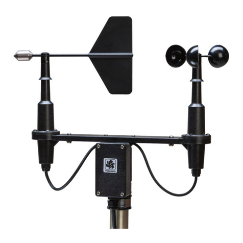
Young 03102L User manual

METEOROLOGICAL INSTRUMENTS
INSTRUCTIONS
R.M. YOUNG COMPANY 2801 AERO PARK DRIVE, TRAVERSE CITY, MICHIGAN 49686, USA
TEL: (231) 946-3980 FAX: (231) 946-4772 WEB: www.youngusa.com P/N: 03102L-90
REV: A122816
WIND SENTRY ANEMOMETER
MODEL 03102L

Page 1
03102L-90 (A))
MODEL 03102L
WIND SENTRY ANEMOMETER
(WITH 4-20mA OUTPUTS)
INTRODUCTION
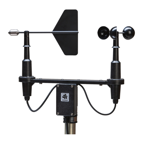
The Wind Sentry Anemometer measures horizontal wind speed. The
small size, simplicity, and corrosion resistant construction provide
a professional quality instrument at a modest cost. The cup wheel
shaft uses stainless steel precision instrument grade ball bearings
which are lubricated with a wide temperature range high quality
instrument oil. Standard bearings have light contacting seals to
exclude contamination and help retain lubricant for longer service life.
Cup wheel rotation produces an AC sine wave voltage signal with
frequency proportional to wind speed. Internal circuitry converts
the raw signal to 4 to 20 mA current output over the specied 0 to
50 m/s wind speed range.
The sensor mounts on standard 1 inch pipe, outside diameter
34 mm (1.34") and is supplied with a cross arm and junction box
for cable connections. Wind Sentry anemometers and wind vanes
are available separately with similar mounting and junction box.
INITIAL CHECK-OUT
When the Wind Sentry is unpacked, check it carefully for any signs
of shipping damage.
Place the cup wheel on the anemometer shaft and secure it by
tightening the set screw on the side of the hub. The instrument is
fully calibrated before shipment; however, it should be checked both
mechanically and electrically before installation. The cup wheel
should easily rotate 360° without friction.
INSTALLATION
Proper placement of the instrument is very important. Eddies from trees,
buildings, or other structures can greatly inuence wind speed and
direction observations. To get meaningful data for most applications,
locate the instrument well above or upwind of such obstructions. As a
general rule, the air ow around a structure is disturbed to twice the
height of the structure upwind, six times the height downwind, and
twice the height of the structure above ground. For some applications
it may not be practical or necessary to meet these requirements.
Grounding the Wind Sentry is vitally important. Without proper
grounding, static electrical charge can build up during certain
atmospheric conditions and discharge through the transducers. This
discharge may cause erroneous signals or transducer failure. To
direct the discharge away from the transducers, housings in which the
transducers are mounted are made with a special anti-static plastic.
It is important that the mounting post be connected to a good earth
ground. There are two ways this may be accomplished. First, the
Wind Sentry may be mounted on a metal pipe which is connected
to earth ground. The mounting pipe should not be painted where the
Wind Sentry is mounted. Towers or masts set in concrete should be
connected to one or more grounding rods. If it is difcult to ground the
mounting post in this manner, the following method should be used.
Inside the junction box the screw labeled EARTH GND is connected
to the anti-static housings. This terminal should be connected to an
earth ground (Refer to wiring diagram).
To install the Wind Sentry, follow these steps:
1. MOUNT WIND SENTRY
a) Connect sensor cable to Wind Sentry junction box.
b) Place Wind Sentry on mounting post.
d) Tighten mounting post band clamp.
c) Connect sensor cable to measuring instrument as shown
in manual.
WIND SPEED SPECIFICATION SUMMARY
Range 0 to 50 m/s (112 mph)
Gust Survival 60 m/s (134 mph)
Sensor Ø 12 cm cup wheel assembly
Ø 40 mm hemispherical cups
Turning Factor 75 cm (2.46 ft)
Distance Constant 2.3 m (7.5 ft.) for 63% recovery
Threshold Sensitivity 1.1 m/s (2.5 mph)
Transducer Stationary coil
1300 Ohm nominal DC resistance
Output Signal 4-20 mA = 0-50 m/s
GENERAL
Power Requirement: 8 - 30 VDC
Operating Temperature: -50 to 50°C (-58 to 122°F)

Page 2
03102L-90 (A)
CALIBRATION
The Wind Sentry is fully calibrated before shipment and should
require no adjustments. Recalibration may be necessary after some
maintenance operations. Periodic calibration checks are desirable
and may be necessary where the instrument is used in programs
which require auditing of sensor performance.
Wind speed calibration is determined by the cup wheel turning factor
and the output characteristics of the transducer. The calibration
formula relating cup wheel rpm to wind speed is shown below.
Standard accuracy is ±0.5 m/s (1.1 mph). For greater accuracy, the
sensor must be individually calibrated in comparison with a wind
speed standard. Contact the factory or your supplier to schedule a
NIST (National Institute of Standards & Technology) traceable wind
tunnel calibration in our facility.
To calibrate wind system electronics, temporarily remove the cup
wheel and connect a Model 18802 Anemometer Drive to the cup
wheel shaft. Apply the calibration formula to the motor rpm and adjust
the signal conditioning electronics for proper value. For example,
with the cup wheel shaft turning at 1800 rpm, adjust the indicator
to display 22.7 meters per second. (0.01250 X 1800 + 0.2 = 22.7))
CALIBRATION FORMULAS
Model 03102L Wind Sentry Anemometer
WIND SPEED vs CUP WHEEL RPM
m/s = (0.01250 x rpm) + 0.2
knots = (0.02427 x rpm) + 0.4
mph = (0.02795 x rpm) + 0.4
km/h = (0.04499 x rpm) + 0.7
WIND SPEED vs mA OUTPUT
m/s = ((mA - 4.06) x 3.125) + 0.2
knots = ((mA - 4.05) x 6.0745) + 0.4
mph = ((mA - 4.05) x 6.9904) + 0.4
km/h = ((mA - 4.06) x 11.2500) + 0.7
MAINTENANCE
Given proper care, the Wind Sentry should provide years of
service. Because of its durable, corrosion resistant construction,
the instrument requires little maintenance. The only components
likely to require replacement due to normal wear are the precision
ball bearings. Replacement of these components should only be
performed by a qualied instrument technician. If service facilities
are not available, return the instrument to the factory. Refer to the
accompanying drawings to become familiar with part names and
locations. Maximum torque on all set screws is 80 oz-in.
ANEMOMETER FLANGE BEARING REPLACEMENT
If anemometer bearings become noisy or wind speed threshold
increases above an acceptable level, replace the bearings. Check
bearing condition by hanging an ordinary paper clip (0.5 gm) on the
outside edge of one cup while the instrument is held in a horizontal
position. The cup should rotate downward. Failure to rotate due to
the weight of the paper clip indicates anemometer bearings need
replacement. Repeat this test at different positions to check full
bearing rotation. Replace bearings as follows:
1. REMOVE BEARINGS
a) Loosen set screw on side of cup wheel hub. Remove cup
wheel.
b) Remove three screws which hold two sections of main
housing.
c) Carefully separate upper and lower housing. Remove coil
transducer assembly from upper housing. Do not disconnect
from circuit board.
d) Loosen screw and remove ring magnet on end of shaft
inside upper housing.
e) Slide shaft and skirt assembly out of both upper and lower
bearings.
f) Using knife blade under bearing ange, carefully remove
upper bearing.
g) Using a pencil, gently push out lower bearing from above.
2. INSTALL NEW BEARINGS
a) Insert new upper bearing. Use care not to apply excessive
pressure.
b) Slide cup wheel shaft through upper bearing.
c) Slide lower bearing on shaft inside upper housing.
d) Using ring magnet assembly, push lower bearing into
its seat in upper housing.
e) Secure ring magnet to shaft using screw removed in step
1d. Use a small amount of sealant on screw to prevent it
from loosening.
f) Join two housing sections. Secure using three screws
removed in step 1b.
g) Place cup wheel on shaft. Tighten set screw on side of hub.
Do not exceed 80 oz-in torque.
Page 3
03102L-90 (A))
EMC COMPLIANCE
This device complies with Part 15 of the FCC Rules. Operation
is subject to the following two conditions: (1) this device may not
cause harmful interference, and (2) this device must accept any
interference received, including interference that may cause
undesired operation.
This equipment has been tested and found to comply with the
limits for a Class A digital device, pursuant to part 15 of the FCC
Rules. These limits are designed to provide reasonable protection
against harmful interference when the equipment is operated in a
commercial environment. This equipment generates, uses, and
can radiate radio frequency energy and, if not installed and used
in accordance with the instruction manual, may cause harmful
interference to radio communications. Operation of this equipment
in a residential area is likely to cause harmful interference in which
case the user will be required to correct the interference at his own
expense.
This ISM device complies with Canadian ICES-001.
Cet appareil ISM est conforme à Ia norme NMB-001 du Canada.
EN55011/CISPR 11, Group 1, Class B device.
Class B equipment is suitable for use in domestic establishments
and in establishments directly connected to a low voltage power
supply network which supplies buildings used for domestic
purposes.
Note:
Wind Sentry sensors with Line Driver Output may be disrupted
by radiated RF interference at 240-300 MHz. To meet EMC
Compliance, (2) YOUNG 18500 ferrite chokes must be installed
on the cable, one near the sensor, and one near the recording
instrument. (Each choke must have the cable pass through the
center hole at least 2 times, creating 1 loop around the outside as
shown below.)
WARRANTY
This product is warranted to be free of defects in materials and
construction for a period of 12 months from date of initial purchase.
Liability is limited to repair or replacement of defective item. A copy
of the warranty policy may be obtained from R. M. Young Company.
CE COMPLIANCE
This product has been tested and complies with European
CE requirements for the EMC Directive. Please note that shielded
cable must be used.

Page 4
03102L-90 (A)
CABLE & WIRING DIAGRAM
MODEL 03102L WIND SENTRY ANEMOMETER

Page 5
03102L-90 (A))
CIRCUIT DIAGRAM
MODEL 03102L WIND SENTRY ANEMOMETER
(03640BM WIND LINE DRIVER)
CIRCUIT SCHEMATICS

Page 6
03102L-90 (A)
03126S (2)
FLANGE BEARING
03110 CUP WHEEL ASSY
03117
SHAFT WITH HUB
05121E-10
J-BOX COVER ASSY
03640BM J-BOX CB ASSY
03022 (11cm)
CROSSARM MTG ASSY
03125 UPPER HOUSING
(CUT AWAY FOR CLARITY)
03133 RING MAGNET ASSY
#3-48 x 3/8 MACH SCR
03130
COIL TRANSDUCER ASSY
05129
BAND CLAMP
03150
SENTRY PC BOARD
03127 LOWER HOUSING
(CUT AWAY FOR CLARITY)
00321-0810P #8-32 X 5/8" MACH SCR
00322-0800E #8-32 SS STOP NUT
00320-0608P (3)
#6 X 1/2" SELF TAP SCR
00321-0406T (3)
#4 X 3/8" SELF TAP SCR
R. M. YOUNG COMPANY
2801 Aero Park Drive , Traverse City, Michigan 49686 U.S.A.
TEL (231) 946-3980 FAX (231) 946-4772
GENERAL ASSEMBLY & REPLACEMENT PARTS
MODEL 03102L WIND SENTRY ANEMOMETER
18500 FERRITE CHOKE (2)
Table of contents
Other Young Measuring Instrument manuals

Young
Young 06201 User manual

Young
Young 27106T User manual

Young
Young 03002L User manual

Young
Young 86000-SDI User manual

Young
Young 32400 SERIAL INTERFACE User manual

Young
Young 27106 User manual

Young
Young 05631C User manual

Young
Young 86004-SDI User manual

Young
Young 81000 Reference manual

Young
Young Wind Sentry Series User manual