Young 06201 User manual

METEOROLOGICAL INSTRUMENTS
INSTRUCTIONS
R.M. YOUNG COMPANY 2801 AERO PARK DRIVE, TRAVERSE CITY, MICHIGAN 49686, USA
TEL: (231) 946-3980 FAX: (231) 946-4772 WEB: www.youngusa.com PN: 06201-90
REV: K111215
WIND TRACKER
MODEL 06201

Page 1
06201-90(K)
MODEL 06201
WIND TRACKER
SPECIFICATIONS
Size:
144 mm (5.65 in) x 144 mm (5.65 in) x 36 mm (1.4 in)
Panel Cutout: 138 mm (5.43 in) x 138 mm (5.43 in)
Sensors: Wind Monitor (05), Wind Monitor-AQ (05A), Wind
Monitor-SE (09), Ultrasonic Anemometer (09), Wind
Monitor-JR (04), Wind Sentry (03), Wind Monitor
HD (Hd)
Accuracy: ±0.6% Full Scale
Serial I/O: Proprietary binary I/O for master-remote display or
simple ASCII text output for external device: ss.s
ddd<cr><lf>
ss.s windspeed (m/s)
ddd wind direction in degrees
RS-485 half-duplex, 9600 baud,
8-1-n, no handshaking
Other inputs: 4-20 mA (0-360 deg, Ldi 0-50 m/s, Ld2 0-100 m/s)
Other outputs: 0-5 VDC = 0-360° or 0-540°
0-5 VDC = 0-100 m/s
Alarm Relays: Normally Open contacts for WS and WD Contact
rating 24 VAC or 30 VDC maximum 5A resistive,
2A inductive maximum
Input Power: 12-30 VDC, 3.5 W
Weight: 1.0 lb (0.45 kg) without AC adapter
INTRODUCTION
The YOUNG Model 06201 Wind Tracker is a compact wind speed
and direction display with advanced features for use in a wide range
of applications.
FEATURES
• 3-digit wind speed display
• 3-digit maximum wind speed or wind direction display
• Multi-color wind direction display with variability
• Wind speed and direction alarms with delay
• RS-485 serial connections
• Calibrated 0-5 VDC outputs
• Display brightness control
PRECAUTIONS
• INDOOR USE ONLY!
(Unless placed in approved enclosure)
• Operating temperature range:
0-50°C (32-122°F), 0-95% RH
• Use only recommended power sources.
(12-30 VDC, 3.5 W )
• Disconnect power when connecting or servicing
• Alarm contact rating 24 VAC/30 VDC,
(5 A resistive, 2 A inductive maximum)
MOUNTING AND START-UP
1. For best visibility, place the Wind Tracker in a location free of
direct sunlight. Mount it using the attached bracket or remove
bracket for ush mounting to a bulkhead or panel cutout. Panel
cutout dimensions are given in the specications. An optional
rack mounting panel (Model 06280) and protective enclosure
(Model 06260) are available from your YOUNG supplier.
2. Connect cables to terminals according to wiring diagram.
IMPORTANT NOTE! Please observe correct position of back
panel Input Selector Switch according to wiring diagram.
3. Connect GND terminal to suitable earth ground.
4. Insert power supply plug into power jack, plug power supply into
a suitable AC wall outlet or connect to suitable 12 to 30 VDC
power source to terminals.
IMPORTANT NOTE! Do not connect more than one power
source to the Wind Tracker at the same time.
5. When power is applied, the Wind Tracker will display rmware
version number then begin to display wind information as follows:
• Wind speed
• Wind speed units
• Maximum wind speed or direction degrees
• Wind direction (single orange indicator)
• Direction variability (green indicators)
• Alarm status indicators (if selected)
• Wind speed & direction averaging indicator (if selected)
6. Observe display to conrm proper operation.

Page 2
06201-90(K)
FACTORY DEFAULT SETTINGS
INPUT:
- Sensor Input Setting: "05" Wind Monitor
- Input selector switch position: "Down" (Sensor)
OPTIONS:
- Averaging: "No"
- Right hand display window: "Max Wind Speed"
- Alarms: "No"
OUTPUT:
- Voltage Outputs: 0-5Vdc=0-100m/s / 0-5Vdc = 0-360°
- Serial Output Type: "Binary"
IMPORTANT NOTE!:
Before connecting any external devices, verify the above settings
are compatible with your application. If different, refer to the
wiring diagrams for the correct settings.
CHANGING SETTINGS
Wind Tracker parameters may be inspected or changed in SETUP
mode which is enabled by simultaneously pressing both ENTER and
SELECT keys for about 4 seconds. When SETUP mode is active,
abbreviations identify each function and available options as listed
below. The SELECT key changes options or values. The ENTER key
saves and moves to the next parameter.
Appearance of options depends on parameter settings. Some
options may be hidden.
DISPLAY SETUP FUNCTION
Input / Sensor Type
InP 03 Wind Sentry
04 Wind Monitor-Jr
05 Wind Monitor
05A Wind Monitor-AQ
09 Wind Monitor-SE or YOUNG sonic anemometer
SEr Serial input when used as remote display
Ld2 Line Driver 4-20mA input (0-100 m/s)
Hd Wind Monitor HD
Ldi Line Driver 4-20mA input (0-50 m/s)
Wind Speed Units (annunciator blinks)
SPd unt SELECT key changes units. ENTER to save
Display Averaging (annunciator blinks)
dSP no Instantaneous data displayed
YES Average data displayed
PEr 030 Set averaging period in seconds (0-999).
Display will update at this interval.
Right Display Window Selection
dSP SPd Maximum wind speed
dir Wind Direction degrees
Wind Direction Alarm (annunciator blinks)
ALr no Direction alarm not armed
YES Direction alarm armed
ALr dir SELECT key sets direction alarm sector start.
ENTER key saves.
ALr SPn SELECT key sets direction alarm sector span.
ENTER key saves.
Wind Speed Alarm (annunciator blinks)
ALr no Speed alarm not armed
YES Speed alarm armed
ALr 000 Alarm set-point. SELECT key increments value.
ENTER key saves.
FRONT PANEL
1. Wind speed display
2. Wind speed units indicator
3. Alarm status indicators
4. Data averaging indicator
5. Maximum wind speed or direction display
6. Wind direction and variability display
7. Brightness control (operate) or Enter key (setup)
8. Maximum Reset (operate) or Select (setup)
BACK PANEL
1. Power input coaxial jack (12-30 VDC)
2. Power input terminals (12-30 VDC)
3. Sensor or 4-20 mA inputs
4. Earth ground connection
5. RS-485 serial input/output
6. 0-5 VDC calibrated outputs
7. Alarm relay connections (Normally Open)
8. Input Selector Switch (Sensor or 4-20mA)

Page 3
06201-90(K)
Alarm Delay Time
dLY 030 Alarm delay time in seconds (0-999). SELECT key
increments value. ENTER key saves.
Sound
Snd no No sound
YES Audible beep with alarm activations or average update.
Wind Direction Voltage Output Scale
dir 360 0-360 degrees
540 0-540 degrees
Serial Output Type
Out bin Binary output for remote Wind Tracker displays
ASC ASCII text wind speed & direction
Test Functions
tSt no No test
YES Test
tSt ALr SELECT key closes alarm relays.
CAL 0.00 SELECT key alternates between 0.00 and
5.00 VDC output to calibrate external devices.
tSt dsP SELECT key tests display sections.
OPERATION
ALARMS
Wind speed and direction alarms each have their own set-point,
LED status indicator, and relay contacts. The Alarm Delay parameter
establishes time duration in or out of the set-point range needed for
the alarm to change state. Front panel LEDs indicate alarm status
during operation.
LED Off = Alarm not armed and OFF. Relay open
LED Steady = Alarm armed and OFF. Relay open
LED Blinking = Alarm armed and ON. Relay closed.
Audible beep if Sound parameter is enabled.
AVERAGING
When averaging is enabled, the front-panel AVG annunciator is
illuminated, and average wind speed and direction values are displayed
at intervals set by the Period (PEr) parameter. When averaging is
disabled, instantaneous wind values are displayed.
BRIGHTNESS
Adjust display brightness by pressing and holding the left BRIGHT
key for 1 second.
MAXIMUM or WIND DIRECTION DISPLAY
Either MAXIMUM WIND SPEED GUST or numerical WIND
DIRECTION appears during operation depending on Right Display
Window (dSP) parameter setting. Maximum gust may be reset during
normal operation by pressing and holding the RESET key for 1 second.
REMOTE DISPLAYS
When set for any non-serial input, the Wind Tracker functions as
a master display source for other Wind Trackers which have been
congured for remote display with InP=SEr. The master Wind Tracker
must also be set for binary serial output (Out=bin).
MASTER: Sensor InP = any non-serial device, Out=bin
REMOTE: Sensor InP = SEr
Connect one Wind Tracker master to up to 16 remote displays via
the RS-485 terminals as shown in wiring diagrams. Remote Wind
Trackers display exactly the same information as the master including
alarm states. MAX RESET and all display features are controlled by
the master unit only. Brightness can be adjusted independently at
each Wind Tracker display.
VOLTAGE OUTPUTS
Calibrated voltage outputs for wind speed and direction are updated
16 times per second. Wind Speed 0-100 m/s = 0.00 to 5.00 VDC.
Wind Direction may be scaled for either 0-360 or 0-540 degrees =
0.00 to 5.00 VDC by setting the Direction (dir) parameter.
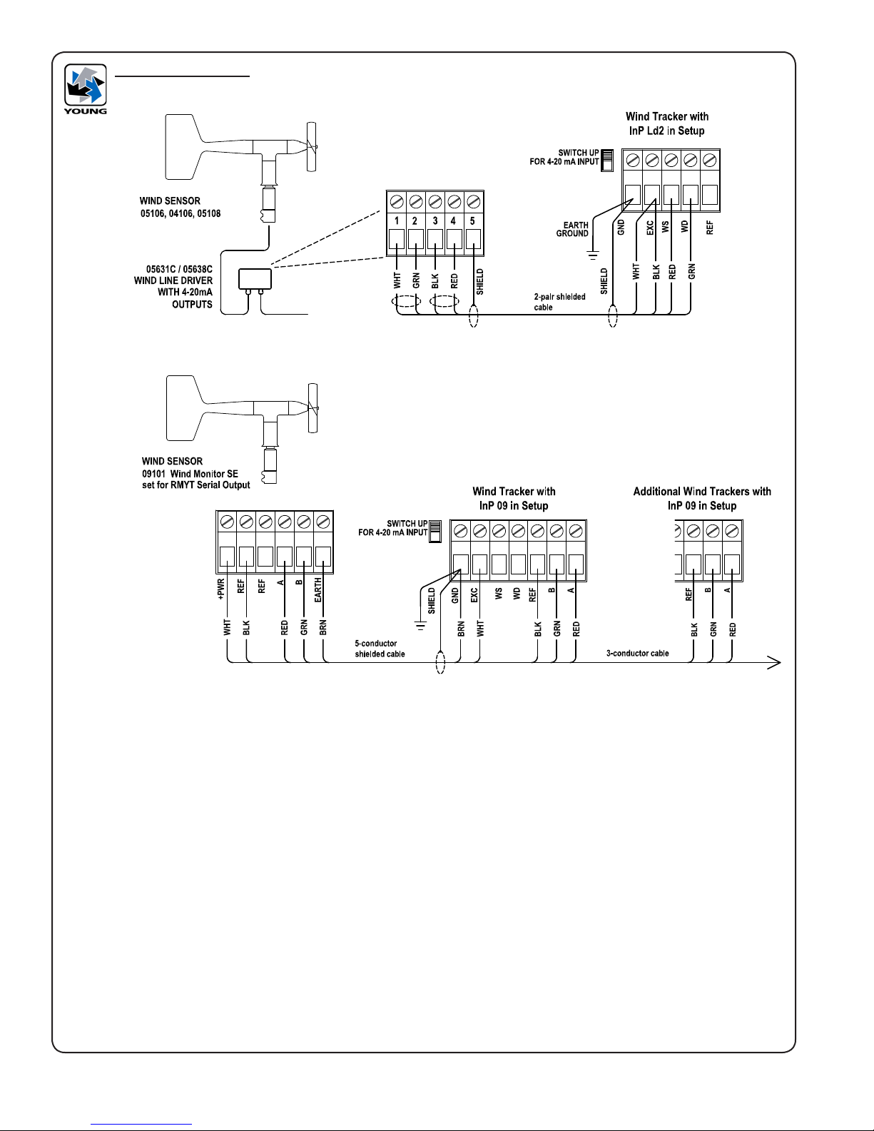
4-20 mA INPUTS
The Wind Tracker accepts 4-20 mA Line Driver inputs with either
0-50 m/s or 0-100 m/s scaling (Ldi and Ld2 input settings). Connect
as shown in wiring diagram. The back-panel switch labeled 4-20 mA
must be in the UP position. 24VDC power is recommended for most
4-20 mA installations.
POWER CONNECTIONS
The Wind Tracker operates from a 12 to 30 VDC power source.
Power may be connected via the coaxial jack or terminals. These
are internally wired in together so DO NOT CONNECT MORE THAN
ONE POWER SOURCE AT THE SAME TIME. See wiring diagrams
for examples.
ERROR MESSAGES
Ldi Err 4-20 mA (line driver) signal is missing or outside an
acceptable range. Verify connections, signal, and
4-20 mA switch in UP position.
SEr Err Unit set to receive RS-485 serial signal (inP=SEr or
09), but no serial data detected. Verify serial source
is working. Verify connections.

Page 4
06201-90(K)
EMC COMPLIANCE
This device complies with Part 15 of the FCC Rules. Operation
is subject to the following two conditions: (1) this device may not
cause harmful interference, and (2) this device must accept any
interference received, including interference that may cause
undesired operation.
This equipment has been tested and found to comply with the
limits for a Class A digital device, pursuant to part 15 of the FCC
Rules. These limits are designed to provide reasonable protection
against harmful interference when the equipment is operated in a
commercial environment. This equipment generates, uses, and
can radiate radio frequency energy and, if not installed and used
in accordance with the instruction manual, may cause harmful
interference to radio communications. Operation of this equipment
in a residential area is likely to cause harmful interference in which
case the user will be required to correct the interference at his own
expense.
This ISM device complies with Canadian /CES-001.
Cet apparei/ISM est conforme a Ia norme NMB-001 du Canada.
EN55011/CISPR 11, Group 1, Class B device
Class B equipment is suitable for use in domestic establishments
and in establishments directly connected to a low voltage power
supply network which supplies buildings used for domestic
purposes.
Note:
Instrument measurements may be disrupted by conducted
RF interference at 13, 35, and 54 MHz.
To meet EMC Compliance, a ferrite core (YOUNG 18500) must
be installed on the wall adapter DC power cable. The cable must
pass through the center hole of the choke at least 4 times, creating
3 loops around the outside as shown below.
18500 FERRITE CHOKE
WARRANTY
This product is warranted to be free of defects in materials and
construction for a period of 12 months from date of initial purchase.
Liability is limited to repair or replacement of defective item. A copy
of the warranty policy may be obtained from R. M. Young Company.
CE COMPLIANCE
This product has been tested and complies with European CE
requirements for the EMC Directive. Please note that shielded cable
must be used.

Page 5
06201-90(K)
WIRING DIAGRAMS

Page 6
06201-90(K)
WIRING DIAGRAMS

Page 7
06201-90(K)
WIRING DIAGRAMS

Page 8
06201-90(K)
Master-Remote Display
Wiring Example
WIRING DIAGRAMS
Other manuals for 06201
1
Table of contents
Other Young Measuring Instrument manuals

Young
Young 05631C User manual

Young
Young ResponseONE 91000 User manual

Young
Young WIND MONITOR-AQ 05305 User manual

Young
Young 03002L User manual

Young
Young Wind Sentry Series User manual

Young
Young 81000 Reference manual

Young
Young 27106T User manual

Young
Young 81000V User manual

Young
Young 09101 User manual

Young
Young 86004 User manual