Young 09101 User manual

METEOROLOGICAL INSTRUMENTS
INSTRUCTIONS
R.M. YOUNG COMPANY 2801 AERO PARK DRIVE, TRAVERSE CITY, MICHIGAN 49686, USA
TEL: (231) 946-3980 FAX: (231) 946-4772 WEB: www.youngusa.com P/N: 09101-90
REV: I111215
WIND MONITOR - SE
MODEL 09101

Page 1
09101-90(I)
MODEL 09101
WIND MONITOR - SE
INTRODUCTION
The Wind Monitor-SE combines the performance and durability
of the standard Wind Monitor with an optically encoded direction
transducer and serial data output capability.
The wind speed sensor is a four blade helicoid propeller that turns
a multipole magnet. Propeller rotation induces a variable frequency
signal in a stationary coil. Slip rings and brushes are not used.
The wind direction sensor is a durable molded vane. An
optical encoder measures vane angle, thereby eliminating the
characteristic deadband and wear of potentiometer transducers.
The encoder is an absolute type so direction output remains
accurate even if power is interrupted.
Raw transducer signals are processed by onboard electronics.
A variety of serial protocols or a conventional calibrated voltage
output may be selected with simple internal jumpers.
The Wind Monitor-SE is designed for superior environmental
resistance. Housing parts are UV stabilized thermoplastic. Fittings
are stainless steel and anodized aluminum. Precision grade
stainless steel ball bearings are used throughout. The instrument
mounts on standard 1 inch pipe.
INITIAL CHECKOUT
Remove the sensor from its shipping carton. Remove the plastic
nut from the propeller shaft and install the propeller with the teeth
on the propeller hub engaging the slots on the shaft hub. Tighten
plastic propeller nut nger-tight only. Do not overtighten.
The instrument is fully balanced, aligned, and calibrated before
shipment. Some simple checks can be made to verify proper
function. Both vane and propeller should rotate easily without
friction. Check vane balance by holding sensor with vane surface
horizontal. The vane should have no tendency to rotate. A slight
imbalance will not degrade performance.
INITIAL SETUP
The 09101 has been calibrated at the factory and requires
no additional adjustments. Operation is configured by onboard
jumpers and software commands.
Unless otherwise specified, the sensor is supplied with the
following settings:
Continuous Serial Output
RMY Protocol
9600 Baud
Meters per Second
Other settings are easily selected by changing the jumper pattern.
Refer to the wiring diagram for jumper J1 and J3 locations. The
following table lists available features and position of each jumper.
Important Note:
Jumper settings are read at power-up only. If jumpers are
changed, remove and reapply power for the new settings to
be used.
At rst power-up the Wind Monitor-SE has a 3 second delay
before outputting the rst wind speed value.
WIND SPEED SPECIFICATION SUMMARY
Range 0 to 100 m/s (224 mph)
Resolution: 0.1 unit
Accuracy: ±0.3 m/s (0.6 mph) or 1% of reading
Threshold: 1.0 m/s (2.2 mph)
Distance constant: 2.7 m (8.9 ft)
Transducer: Rotating magnet and stationary coil.
WIND DIRECTION (AZIMUTH) SPECIFICATION SUMMARY
Range: 0-360 degrees
Accuracy: ± 2 degrees
Resolution: 1 degree
Threshold: 1.1 m/s (2.5 mph) @ 10° displacement
Delay distance: 1.3 m (4.3 ft)
Damping ratio: 0.3
Transducer: Absolute encoder
GENERAL
Power requirement: 11-24 VDC, 20 mA
Dimensions: Overall height 37 cm
Overall length 55 cm
Propeller 18 cm diameter
Mounting 34 mm (1.34 in) diameter
(standard 1 inch pipe)
Weight: Sensor weight 1.0 kg (2.2 lb)
Shipping weight 2.3 kg (5.0 lb)
Voltage Output: WS: 0-5 VDC for 0-100 m/s
WD: 0-5 VDC for 0-540°
Serial RS-485: 2 wire-half duplex, 1200-9600 Baud
RMY, NCAR, NMEA, or RMYT protocols
Polled or continuous
Operating Temperature: -50 to 50°C (-58 to 122°F)

Page 2
09101-90(I)
Jumper setting summary:
DESCRIPTION J1 POSITION
Continuous serial output 1 IN
Polled serial output 1 OUT
RMY protocol 2 IN 3 IN
NCAR protocol 2 IN 3 OUT
NMEA protocol 2 OUT 3 IN
RMYT protocol 2 OUT 3 OUT
1200 baud 4 IN 5 IN
2400 baud 4 IN 5 OUT
4800 baud 4 OUT 5 IN
9600 baud 4 OUT 5 OUT
Knots 6 IN 7 IN
Miles per hour 6 IN 7 OUT
Kilometers per hour 6 OUT 7 IN
Meters per second 6 OUT 7 OUT
DESCRIPTION J3 POSITION
Calibrated 0-5 VDC output LEFT
Serial RS-485 output RIGHT
See wiring diagram for J1 and J3 locations.
SERIAL PROTOCOLS
Details of the various operating modes are described in the
following paragraphs.
Important Note:
When the RS-485 bus is used for both sending data and
receiving commands, the connected device must be capable
of properly managing this type of half-duplex communication.
If the Wind Monitor-SE receives a command that will result in
sending a response, it will wait 25 mS for the device which
issued the command to return to receive mode. When not
sending data, the Wind Monitor-SE stays in receive mode.
RMY PROTOCOL
RMY protocol is a simple scheme suitable for use with the Young
Model 26700 Translator and many dataloggers.
RMY protocol may be used with either single Wind Monitor-SE
sensors (polled or continuous output) or multiple sensors on a
shared bus operating in polled mode.
The default output rate is once per second. Data output format is:
aa ddd sss.s<CR/LF>
“aa” is the 09101 address, (0 -15)
“ddd” is direction in degrees
“sss.s” is speed in units set by jumper J1.
In polled mode, there are two commands:
Ma! “a” is the 09101 address in hex, 0-F.
This command requests the latest reading.
ADa! “a” is the new 09101 address in hex, 0-F.
This command sets the 09101 address.
NCAR PROTOCOL
NCAR protocol uses a subset of the NCAR PAM III protocol. For
full details on the PAM III protocol, contact:
NCAR - Atmospheric Technology Division
P.O. Box 3000
Boulder, Colorado 80307-3000
Two modes of operation are available: bussed and interactive.
Bussed mode is the normal operating mode and requires a full
address/command/checksum sentence for sending commands.
Interactive mode omits the address and checksum requirements
and is intended primarily for benchtop use.
When NCAR protocol is set via jumper J1, the 09101 defaults to
bussed mode when powered up. A sequence of three ESC codes
(ASCII 27) toggles the 09101 between bussed and interactive
mode. The three ESC codes must occur within 2 seconds.
In bussed mode, the data output format is:
&aaW: sss.s dddc<EOT>
“aa” is the 09101 address in hex, 00-FF
“sss.s” is speed
“ddd” is direction in degrees
“c” is a single character pseudo-checksum
<EOT> is the ASCII end-of-transmission character (ASCII 4).
In interactive mode, the data output format is:
&aaW: sss.s ddd<CR/LF>
“aa” is the 09101 address in hex, 00-FF
“sss.s” is speed
“ddd” is direction in degrees
<CR/LF> is the carriage return/line feed pair (ASCII 13 and 10).
Wind speed units are set by jumper J1. The zero reference
direction is preset but may be reset to a new position using the ZN
command.
Commands in bussed mode use the following general format:
#aa[...]c<EOT>
“aa” is the 09101 address in hex, 00-FF
[...] is the command (see below)
“c” is a single character pseudo-checksum
<EOT> is the ASCII end-of-transmission character (ASCII 4).
Commands in interactive mode use this format:
[...]<CR>
[...] is the command
<CR> is a carriage return (ASCII 13).
When operating in continuous output mode, the 09101 will
still receive commands. However, because of the half-duplex
serial bus, commands must be issued between data output
transmissions. If commands arrive while the 09101 is transmitting,
data may be garbled by the collision. In polled mode, collisions are
unlikely since the 09101 responds only when commanded.
Response to commands varies depending on the command and
whether the 09101 is in bussed or interactive mode.
In bussed mode, commands without the “#” prefix or proper

Page 3
09101-90(I)
*Max set screw torque 80 oz-in
address are ignored. Properly addressed but otherwise invalid
commands are responded to as follows:
&aaNUc<EOT> Undened command
&aaNCc<EOT> Bad checksum
&aaNOc<EOT> Other error
Where “aa” is the 09101 address in hex, 00-FF; “c” is a single
ch ara cter pse udo -ch eck sum ; and <EO T> i s the end -of -
transmission character (ASCII 4).
In interactive mode, invalid commands produce this response:
NAK<CR/LF>
NCAR PAM III (SUBSET) COMMAND SUMMARY
Upper and lower case text must be observed with these
commands.
CMD DESCRIPTION RESPONSE
BDddd Boom direction offset none
"ddd" is degrees
CD Continuous output, overrides J1 data
FC Use calibrated speed units &aaFC
FR Use raw speed pulse count &aaFR
MR Manual reset reset
OD Output data data
OS Output status status
PH Print help (abbreviated command list) command list
PM Polled mode, overrides J1 none
PO Print operating parameters parameter list
SAaa Set address, “aa” is new hex address &aa
ZN Set zero direction reference none
calib Enter calibrate mode* none
ratexx Set serial output rate none
"xx" is the delay between each output
in continuous mode. Delay equals the
xx value times 32.77 mS. Examples:
rate02 is about 16/second
rate30 is about once per second
propxxx Set prop pitch none
"xxx" is prop pitch in mm/rev
Example:
Use prop294 for model 08234 propeller,
29.4 cm/rev pitch
NMEA PROTOCOL
Generally used for marine applications, this protocol produces a
standard NMEA output sentence for wind speed and direction at
4800 baud. The sentence is as follows:
$WIMWV,ddd,R,sss.s,U,A*hh<CR/LF>
“ddd” is wind direction in degrees.
“sss.s” is wind speed.
"U" is wind speed units. N = knots, K = km/h, M = m/s, S = mph
"A" is Status
"*hh" is the hex checksum value of output string
This mode may be used for sending NMEA data to the YOUNG
Model 06206 Marine Wind Tracker.
RMYT PROTOCOL
This is a protocol for sending serial wind data directly to a YOUNG
Model 06201 Wind Tracker. The output is a special binary format
sent 16 times per second at 9600 baud.
VOLTAGE OUTPUTS
Voltage output mode is selected with jumper J3 in the left position.
Jumper J1 must be set for RMY, NCAR, or NMEA protocol. Wind
direction voltage output calibration is 0-5 VDC for 0-540° range.
Wind speed voltage output is 0-5 VDC for 0-100 meters per
second.
In applications where long connection cables or small wire gauge
is used, measure the 09101 voltage outputs differentially to
overcome error-inducing voltage drops in the cable or consider
using the serial RS-485 signal which is more tolerant of this effect.
INSTALLATION
Proper placement of the instrument is very important. Eddies from
trees, buildings, or other structures can greatly influence wind
speed and wind direction observations. To get meaningful data,
locate the instrument well away from obstructions. As a general
rule, the air ow around a structure is disturbed to twice the height
of the structure upwind, six times the height downwind, and up to
twice the height of the structure above ground.
FAILURE TO PROPERLY GROUND THE WIND MONITOR-SE
MAY RESULT IN ERRONEOUS SIGNALS
OR DAMAGE TO THE UNIT.
Grounding the Wind Monitor is vitally important. Without proper
grounding, static electrical charge can build up during certain
atmospheric conditions and discharge through the transducers.
This discharge can cause erroneous signals or transducer failure.
To direct the discharge away from the transducers, it is very
important that the sensor be connected to a good earth ground.
Inside the junction box connect the terminal labeled EARTH to a
good earth ground.
Initial installation is most easily done with two people: one to adjust
the instrument position and the other to observe the indicating
device. After initial installation, the instrument can be removed
and returned to its mounting without realigning the vane since the
orientation ring preserves the wind direction reference. Install the
Wind Monitor following these steps:
1. MOUNT WIND MONITOR
a) Place orientation ring on mounting post. Do Not tighten band
clamp yet.
b) Place Wind Monitor on mounting post. Do Not tighten band
clamp yet.
2. CONNECT SENSOR CABLE
a) Remove junction box cover.
b) Route cable thru strain relief opening at bottom of junction
box. Secure cable by tightening packing nut.
c) Connect sensor cable to terminals. See wiring diagram.
Terminals A and B are used for either serial (RS-485) or
voltage outputs depending on the position of jumper J3.
Use a small screwdriver to make connections. Be sure to
securely tighten each terminal.
d) Replace junction box cover.

Page 4
09101-90(I)
3. ALIGN VANE
a) Connect instrument to an indicator.
b) Choose a known wind direction reference point on the
horizon.
c) Sighting down instrument centerline, point nose cone at
reference point on horizon.
d) While holding vane in position, slowly turn base until
indicator shows proper value.
e) Tighten mounting post band clamp.
f) Engage orientation ring indexing pin in notch at instrument
base.
g) Tighten orientation ring band clamp.
CALIBRATION
Periodic calibration checks are desirable and may be necessary
where the instrument is used in programs which require auditing of
sensor performance. Recalibration may be necessary after some
maintenance operations.
An accurate wind direction calibration requires a Vane Angle
Fixture (Young Model 18112 or equivalent). Details are listed under
"VERTICAL SHAFT BEARING REPLACEMENT STEP 10. ALIGN
VANE". The sensor nose cone must be removed if any adjustment
is required.
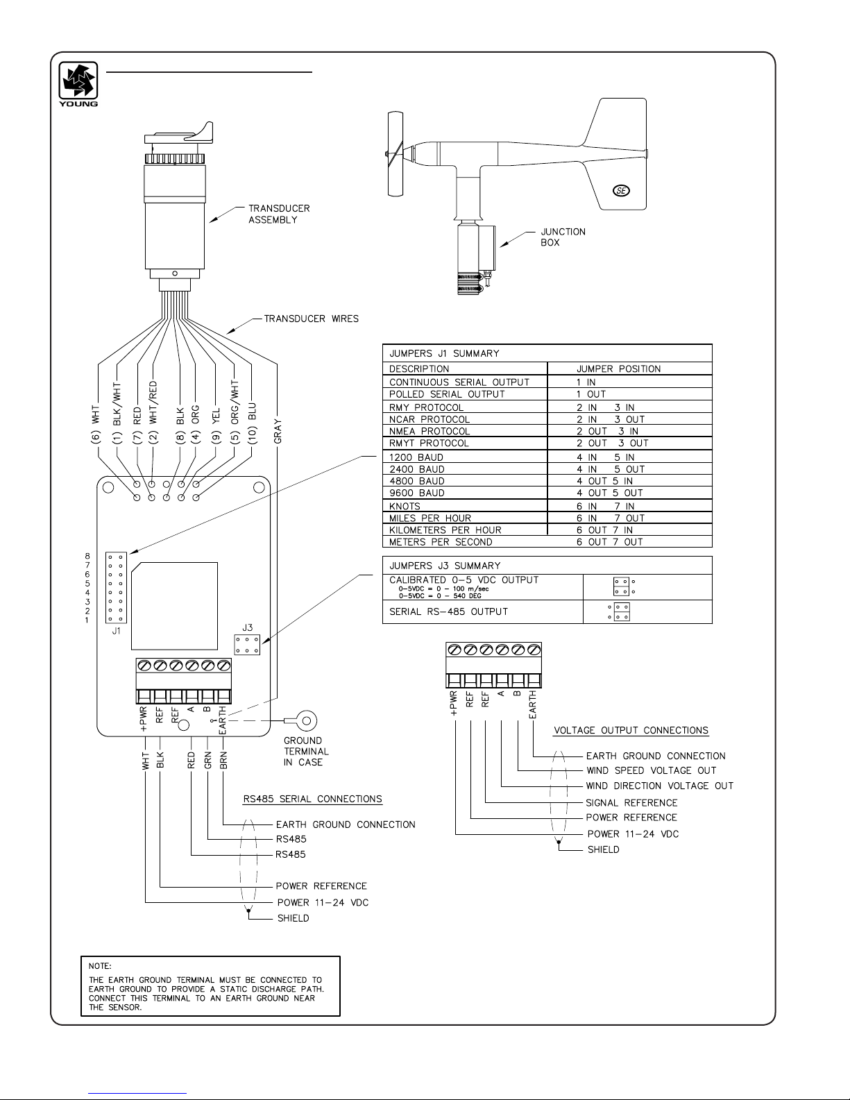
Wind speed calibration is determined by propeller pitch and the
output characteristics of the transducer. Calibration formulas
showing wind speed vs. propeller rpm are shown on the wiring
diagram. Standard accuracy is ± 0.3 m/s (0.6mph). For greater
accuracy, the device must be individually calibrated in comparison
with a wind speed standard. Contact the factory or your YOUNG
supplier to schedule a NIST (National Institute of Standards &
Technology) traceable wind tunnel calibration in our facility.
To check wind calibration using a signal from the instrument,
temporarily remove the propeller and connect an Anemometer
Drive to the propeller shaft. Apply the appropriate calibration
formula to the calibrating motor rpm and check for the proper
value. For example, with the propeller shaft turning at 3600 rpm
adjust an indicator to display 17.6 meters per second (3600 rpm x
0.00490 m/s/rpm = 17.6 m/s).
Details on checking bearing torque, which affects wind speed and
direction threshold, appear in the following section.
CALIBRATION FORMULAS
Model 09101 Wind Monitor-SE w/08234 Propeller
WIND SPEED vs PROPELLER RPM
m/s = 0.00490 x rpm
knots = 0.00952 x rpm
mph = 0.01096 x rpm
km/h = 0.01764 x rpm
MAINTENANCE
Given proper care, the Wind Monitor should provide years of
service. The only components likely to need replacement due
to normal wear are the precision ball bearings. Only a qualified
instrument technician should perform the replacement. If service
facilities are not available, return the instrument to the company.
Refer to the drawings to become familiar with part names and
locations. Maximum torque on all set screws is 80 oz-in.
FLANGE BEARING REPLACEMENT
If anemometer bearings become noisy or wind speed threshold
increases above an acceptable level, bearings may need
replacement. Check anemometer bearing condition using a
Model 18310 Propeller Torque Disc. Without it, a rough check
can be performed by adding an ordinary paper clip (0.5 gm) to
the tip of a propeller blade. Turn the blade with the paper clip to
the "three o'clock" or "nine o'clock" position and gently release it.
Failure to rotate due to the weight of the paper clip indicates that
the anemometer bearings need replacement. Repeat this test at
different positions to check full bearing rotation. If needed, bearings
are replaced as follows.
1. REMOVE OLD BEARINGS
a) Unscrew nose cone. Do not lose o-ring seal.
b) Loosen set screw on magnet shaft collar and remove
magnet.
c) Slide propeller shaft out of nose cone assembly.
d) Remove front bearing cap which covers front bearing.
e) Remove front and rear bearings from nose cone assembly.
Insert edge of a pocket knife under bearing ange and lift it
out.
2. INSTALL NEW BEARINGS
a) Insert new front and rear bearings into nose cone.
b) Replace front bearing cap.
c) Carefully slide propeller shaft thru bearings.
d) Place magnet on propeller shaft allowing 0.5 mm (0.020")
clearance from rear bearing.
e) Tighten set screw on magnet shaft collar. Do not overtighten.
f) Screw nose cone into main housing until o-ring seal is
seated. Be certain threads are properly engaged to avoid
cross-threading.
VERTICAL SHAFT BEARING REPLACEMENT
Vertical shaft bearings are much larger than the propeller shaft
bearings. Ordinarily, these bearings will require replacement less
frequently. In many cases, they may last the life of the sensor.
Check bearing condition using a Model 18331 Vane Torque
Gauge. Without it, a rough check can be performed by holding
the instrument with the vane horizontal and placing a 3 gm weight
near the aft edge of the n. Failure of the vane to rotate downward
indicates the bearings need replacement.
1. REMOVE MAIN HOUSING
a) Unscrew nose cone from main housing. Retain O-ring for
reuse.
b) Gently push main housing latch.
c) While pushing latch, lift main housing up and remove it from
vertical shaft bearing rotor.
2. UNSOLDER TRANSDUCER WIRES
a) Remove junction box cover.
b) Remove 3 screws holding circuit board.
c) Unsolder transducer wires from circuit board. 9 wires
attach at upper edge of board, 1 wire attaches at bottom
near cable terminals.

Page 5
09101-90(I)
3. REMOVE TRANSDUCER ASSEMBLY
a) Loosen 2 set screws at base of transducer assembly and
remove assembly from vertical shaft. Use care to avoid
damaging wires.
4. REMOVE BEARING ROTOR by sliding it upward off vertical
shaft.
5. REMOVE OLD BEARINGS AND INSTALL NEW BEARINGS.
When inserting new bearings, be careful not to apply pressure
to bearing shields.
6. REPLACE BEARING ROTOR ON VERTICAL SHAFT
7. REPLACE TRANSDUCER ASSEMBLY. Tighten set screws to
80 oz-in.
8. RECONNECT TRANSDUCER WIRES
a) Gently pull wires through hole in junction box. Needle nose
pliers or a bent wire may be used.
b) Carefully solder wires to circuit board according to
wiring diagram. Observe color code.
c) Secure circuit board in junction box using 3 screws
removed in step 2b. Do not overtighten.
9. REPLACE MAIN HOUSING
a) Position main housing over bearing rotor. Be careful to align
indexing key inside main housing with slot in rotor.
b) Turn direction-adjust thumbwheel until notch in coupling
is away from front opening and aligned with ridge inside
housing. Set screw in coupling should face the front opening.
c) With coupling oriented, continue to push main housing onto
bearing rotor until latch locks into place with a click.
10. ALIGN VANE
a) Connect sensor to indicator.
b) Install sensor on vane angle xture (Young Model 18112 or
equivalent) with junction box at 180° or South position.
c) Align sensor to known angular position. If indicator output
varies more than ±1 ° from known angle, loosen setscrew
in direction adjust thumbwheel and slowly turn thumbwheel
until correct output value is obtained. Tighten setscrew.
d) Verify correct angular values at other vane positions.
11. REPLACE NOSE CONE
a) Screw nose cone into main housing until o-ring seal is
seated. Be careful to avoid cross-threading.
WARRANTY
This product is warranted to be free of defects in materials and
construction for a period of 12 months from date of initial purchase.
Liability is limited to repair or replacement of defective item. A copy
of the warranty policy may be obtained from R. M. Young Company.
CE COMPLIANCE
This product has been tested and complies with European CE
requirements for the EMC Directive. Please note that shielded
cable must be used.
EMC COMPLIANCE
This device complies with Part 15 of the FCC Rules. Operation
is subject to the following two conditions: (1) this device may not
cause harmful interference, and (2) this device must accept any
interference received, including interference that may cause
undesired operation.
This equipment has been tested and found to comply with the
limits for a Class A digital device, pursuant to part 15 of the FCC
Rules. These limits are designed to provide reasonable protection
against harmful interference when the equipment is operated in a
commercial environment. This equipment generates, uses, and
can radiate radio frequency energy and, if not installed and used
in accordance with the instruction manual, may cause harmful
interference to radio communications. Operation of this equipment
in a residential area is likely to cause harmful interference in which
case the user will be required to correct the interference at his own
expense.
This ISM device complies with Canadian ICES-001.
Cet appareil ISM est conforme à Ia norme NMB-001 du Canada.
EN55011/CISPR 11, Group 1, Class B device.
Class B equipment is suitable for use in domestic establishments
and in establishments directly connected to a low voltage power
supply network which supplies buildings used for domestic
purposes.

Page 6
09101-90(I)
CABLE & WIRING DIAGRAM
MODEL 09101 WIND MONITOR-SE

Page 7
09101-90(I)
BEARING REPLACEMENT & POTENTIOMETER ADJUSTMENT

Page 8
09101-90(I)
05194 PROPELLER NUT WRENCH
08234 PROPELLER - 18CM X 30CM (BLACK PP)
05163PG FLANGE BEARING (2)
05160CS NOSE CONE (CONDUCTIVE)
05158 NOSE CONE O-RING
05161A 6-POLE MAGNET &
SHAFT COLLAR
09154
MAIN HOUSING AND
TAIL ASSY - SE
05138A
POTENTIOMETER COUPLING
05139
POT ADJUST THUMBWHEEL
09120 OPTICAL ENCODER
TRANSDUCER
05124VG (2)
VERTICAL SHAFT BEARING
05187 PROPELLER NUT 1/4-20
05164C PROPELLER SHAFT W/HUB
6-32 x 1/8 SET SCREW (5)
05127 MAIN HOUSING LATCH
6-32 x 3/8 FLAT HD SCREW
05126CS VERTICAL SHAFT
BEARING ROTOR (CONDUCTIVE)
05121E-10
JUNCTION BOX COVER
09124 SE PROCESSOR BOARD ASSY
4-40 x 5/16 SCREW (3)
05121E
MOUNTING POST ASSEMBLY
05129 BAND CLAMP
(INCL. W/ 05121E, 05128B)
05128B ORIENTATION RING
05165B FRONT BEARING CAP
R. M. YOUNG COMPANY
2801 Aero Park Drive , Traverse City, Michigan 49686 U.S.A.
TEL (231) 946-3980 FAX (231) 946-4772
GENERAL ASSEMBLY & REPLACEMENT PARTS
MODEL 09101 WIND MONITOR-SE

Page 9
09101-90(I)
Calibration Accessories
Model 18802
Anemometer Drive
Model 18112
Vane Angle Bench Stand
Model 18310
Propeller Torque Disc
Model 18331 Vane Torque Gauge
Model 18301
Vane Alignment Rod
Model 18212
Vane Angle Fixture-Tower Mount

Page 10
09101-90(I)
Model 18802 Anemometer Drive provides a convenient and accurate way to rotate an anemometer shaft at
a known rate. The motor may be set to rotate clockwise or counter-clockwise at any rate between 200 and
15,000 RPM in 100 RPM increments. The LCD display is referenced to an accurate and stable quartz timebase.
For completely portable operation, the unit can be operated on internal batteries. For extended operation, an
AC wall adapter is included.
Model 18811 Anemometer Drive is identical to Model 18802 except the drive motor incorporates a
gear reducer for operation in the range of 20 to 990 RPM in 10 RPM increments. The lower range
is recommended for cup anemometer calibration.
Model 18112 Vane Angle Bench Stand is used for benchtop wind direction calibration of the Wind Monitor
family of sensors. The mounting post engages the direction orientation notch on the Wind Monitor. An easy to
read pointer indicates 0 to 360 degrees with 1/2 degree resolution.
Model 18212 Vane Angle Fixture - Tower Mount similar to the Model 18112, the tower mount feature allows use
on the tower as well as the bench top. The fixture is temporarily placed on the tower between the Wind Monitor
and its tower mounting. Index keys and notches are engaged to preserve direction reference.
Model 18310 Propeller Torque Disc checks anemometer bearing torque with 0.1 gm/cm resolu-
tion. The disc temporarily replaces the propeller for torque measurement or simple yet accurate pass/fail
checks. Charts included with the unit relate torque to propeller threshold with limits for acceptable
bearing performance.
Model 18312 Cup-Wheel Torque Disc checks cup anemometer bearing torque.
Model 18331 Vane Torque Gauge checks vane bearing torque of the Wind Monitor family sensors. Slip the
fixture over the main housing and make simple yet accurate vane torque measurements. Charts relating vane
torque to vane threshold provide limits for acceptable bearing performance.
Model 18301 Vane Alignment Rod helps align the vane of a wind sensor to a known direction reference during
installation. The base of the device has an index key that engages the direction orientation notch in the sensor
allowing the sensor to be removed without losing wind direction reference.
Specifications subject to change without notice.
YOUNG
Specifications
Ordering Information MODEL
R.M. YOUNG COMPANY
2801 Aero Park Drive
Traverse City, Michigan 49686 USA
TEL: (231) 946-3980 FAX: (231) 946-4772
E-mail: [email protected]
Web Site: www.youngusa.com
ANEMOMETER DRIVE 200 to 15,000 RPM .............................................. 18802
ANEMOMETER DRIVE 20 TO 990 RPM .................................................. 18811
230V / 50-60 HZ INPUT POWER ................................................... ADD SUFFIX “H”
VANE ANGLE BENCH STAND .......................................................... 18112
VANE ANGLE FIXTURE - TOWER MOUNT ........................................... 18212
PROPELLER TORQUE DISC............................................................ 18310
CUP-WHEEL TORQUE DISC ........................................................... 18312
VANE TORQUE GAUGE ................................................................. 18331
VANE ALIGNMENT ROD ................................................................ 18301
Copyright © 2000 R.M. Young Company, Printed in U.S.A. 11/00
Range:
200 to 15,000 RPM in 100 RPM increments
Rotation:
Clockwise or Counter-Clockwise
Display Resolution:
1 RPM
Quartz Timebase Reference:
0.1 RPM
Power Requirement:
2x9 V (alkaline or lithium) batteries
115 VAC wall adapter included
(230 VAC – add suffix H)
Range:
20 to 990 RPM in 10 RPM increments
Display Resolution:
0.1 RPM
Range:
0 to 360 degrees
Resolution:
0.5 degree
Range:
0 to 5.4 gm-cm
Resolution:
0.1 gm-cm
Range:
0 to 50 gm-cm
Resolution:
5 gm-cm
MODEL 18802 ANEMOMETER DRIVE
(Replaces 18801)
MODEL 18310, 18312 TORQUE DISC DEVICES
Calibration Accessories
MODEL 18811 ANEMOMETER DRIVE
(Replaces 18810)
MODEL 18112, 18212 VANE ANGLE
CALIBRATION DEVICES
MODEL 18331 VANE TORQUE GAUGE
Table of contents
Other Young Measuring Instrument manuals

Young
Young 85000 User manual

Young
Young 86004-SDI User manual

Young
Young 03002L User manual

Young
Young 81005A User manual

Young
Young 06201 User manual

Young
Young ResponseONE 91000 User manual

Young
Young 81000V User manual

Young
Young WIND MONITOR-AQ 05305 User manual

Young
Young 06201 User manual

Young
Young 27106 User manual

Young
Young 86000-SDI User manual

Young
Young 32400 SERIAL INTERFACE User manual

Young
Young 05631C User manual

Young
Young 03102L User manual

Young
Young 27106T User manual

Young
Young 81000 Reference manual

Young
Young 86004 User manual

Young
Young Wind Sentry Series User manual

Young
Young Wind Sentry 03002V User manual