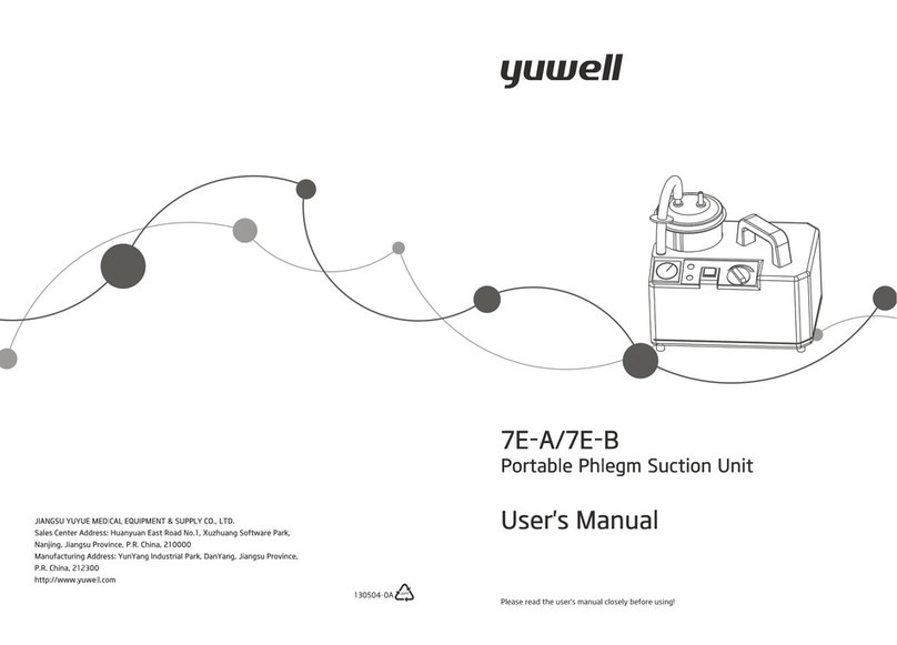
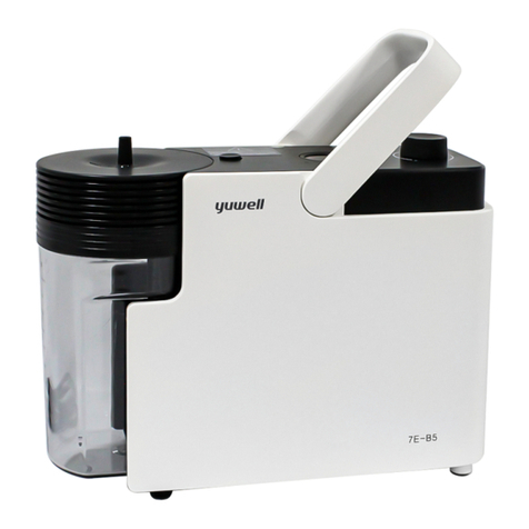
Yuwell 7E-B5 User manual

130513-0A
User's Manual
Please read the user's manual closely before using!
7E-B5
Portable Phlegm Suction Unit
JIANGSU YUYUE MEDICAL EQUIPMENT & SUPPLY CO., LTD.
Sales Center Address: Huanyuan East Road No.1, Xuzhuang Software
Park, Nanjing, Jiangsu Province, P.R. China, 210000
Manufacturing Address: YunYang Industrial Park, DanYang, Jiangsu
Province, P.R. China, 212300
http://www.yuwell.com
7E-B5

Danger: Reduces the risk of electric shock
Warning: This product is precision manufactured, finely assembled
and wired, so do not disassemble or attempt to repair.All repairs
must be carried out by qualified personnel at authorized repair
centers.
1. Cut off the power immediately after each use.
2. Immediately cut off the power When the machine falls into water rather
than reach for it
3. Do not place or store the machine where water or other liquid is easy to
drip.
4. Do not touch the machine when it is wet.
5. Do not disassemble the machine.Services shall be performed by
qualified service personnel.
6. Regularly check the electrical safety index of the machine.
1. When the machine is powered on, it shall not be left unattended.
2. Timely monitor the products when they are used by children or
individuals.
3. This manual only describes the usage of the product.Do not use
accessories other than the manufacturer's recommendation.This will
reduce the performance of the machine.
4. Please do not use the machine and return it to the service center for
inspection and repair when the following situations occur: The power cord
or plug is damaged, the machine can't work properly, the machine has been
dropped or destroyed, the machine falls into the water and so on.
5. Keep the power cord away from the surface of heating or heating
equipment.
6. Do not block the air vent of the product. Avoid soft cloth, nap and other
similar things in the vent.
7. Do not drop or insert any substance at the orifice of the machine.
8. It should be noted that excessive negative pressure may cause harm to
human body.
CONTENTS
1
Important Safety Rules
Important Safety Rules -------------- ----1
Product Features----------------------------2
Installing and Commissioning-------------------3
Application and Maintenance-------------------6
Precautions--------------------------------9
EMC Instruction-----------------------------10
------
Warning: Reduce the risk of burns, electric shocks, fire or personal injury

Application
Structure & Working Principle
Main Technical Performances
1. High negative pressure, High flow
2. Power Supply: □AC220V □AC230V □AC240 □50HZ □60HZ
3. Input power: 150VA
4. Limit negative pressure: ≥0.08MPa(760mmHg)
Oil free lubrication pump to keep the environment from being polluted by the
oil mist.
Low noise.
Round negative pressure meter, and plastic cover.
No any positive pressure to be generated during running, to ensure reliable
and safe operation.
Negative pressure regulating system can be adjusted steplessly.
Small in size, light in weight and portable.
The operating principle diagram shown as follows:
Portable phlegm suction unit is based on similar products at home and
abroad is a new generation of oil free lubrication suction device, which is
suitable to use by the patient who has difficulty in phlegm removal due to
illness, coma and operation, as well as for aspirating such liquid as pus and
blood during the clinical practice. It is the commonly applied medical device
in the emergency room, operation room, and for nursing in sickroom and
home health care.
To phlegm
suction catheter
Negative pressure regulating vavle
Air filter
Overflow valve subassembly
Vacuum meter
Suction inlet
Exhaust outlet
Liquid holder
Silencer
Vacuum pump
Figure 1:Operating principle diagram
2
Product Features
Installing and Commissioning
The customer shall carefully inspect if the appearance of product is good,
and the varieties & quantities of the attachments are in conformity with
those as indicated in the attached list before installing and commissioning.
Also, the customer shall timely notify the supplier or manufacturer of
damage(s) if any.
Note: Apply small amount of distilled water
around the part (pressed into the holder
mouth) of holder plug during installing,
which is good for tightly pressing the
holder plug and enhancing its sealing.
Open Package Inspection
Normal Operating Conditions
Connecting (See Figure 2)
Ambient temperature:+5℃~+35℃ Relative humidity:30%~80%
Atmosphere pressure:86kPa~106kPa
Note: When storage temperature is below 5℃, please keep the equipment
in normal working condition for at least 4 hours before using.
Figure 2:Tube Connecting Diagram
(with phlegm suction catheter
temporarily not connected)
To the phlegm
suction catheter
3
5. Negative pressure regulating range: 0.02MPa~limit negative pressrue
6. Suction rate: 32L/min±2L/min(760mmHg) (Test under operate the
suction equipment 10s at the maximum vacuum setting)
7. Liquid storage bottle: 1000mL/pc, 1pc
8. Noise: ≤60dB(A)
9. Weight: 3.9kg
10. Dimension: 314×123×233(mm)
The suction unit is not suitable for use in the place with inflammable &
explosive gas.
Duty cycle: 30 minutes on, 30 minutes off.
ClassⅡdevice, Type B application part.
Service life: 5 years(wearing and consumable parts are excluded).

Negative pressure regulating
Inspection & test on the overflow device
Note: Dredge the suction catheter if blocked as per the following method:
Bend the suction conductor in "V" form (with no liquid in the holder), and
release it to the original status when the negative pressure reaches up to
the maximum value. Repeat this procedure several times till the catheter is
not blocked.
Block the suction inlet, open the aspirator switch and regulate the negative
pressure valve, and the readings on the pressure meter shall be within 0.02
MPa ~ limit negative pressure.
Control the negative pressure as required for suction by means of the
negative pressure valve at the time of clinical practice.
Increase the negative pressure by turning the valve clockwise.
Reduce the negative pressure below 0.02 MPa prior to power shut-off.
Turn tightly the negative pressure regulating valve clockwise, and block the
air suction inlet with the finger or the rubber head of dropper, or fold up and
hold the suction tube.
Start the aspirator for running with no strange sound; the pointer of the
vacuum meter will quickly reach up to the limit negative pressure. Release
the air suction inlet, the pointer will return below 0.02 Mpa. If so, the
connector can be regarded as being in good connection.
Attach the phlegm suction catheter. The negative pressure in the negative
pressure system shall be less than 0.07 MPa at the time of attaching F8
suction catheter, less than 0.03MPa when attaching F12 suction catheter. If
so, the phlegm aspirator is considered as being in normal condition.
Connector inspection
4
Power line connection
Connect the plug with the power source. Turn on the power supply, and the
power indicator will illuminate.
Note: The power plug is used for power shut-off, and the power socket
shall be grounded reliably.
Note:
1. The liquid level still continuously ascends after the overflow device has
been shut off, possibly due to:
(1) Residual negative pressure still in the holder.
(2) Valve mouth not fully closed.
For Item (1), the liquid level in the holder will not ascend when the suction
tube conductor is placed again into the liquid as suctioned, and for Item (2),
the liquid level still ascends. Thus, it is required to observe carefully, and lift
immediately the conductor out of the suctioned liquid when the holder is
close to full, then, switch off the aspirator to stop suction, and examine the
possible reason of the valve fault.
2. The float is still adhered on the valve mouth as already closed by the
float, possibly due to the negative pressure in the line. At this moment,
release the regulating valve or shut off the aspirator (to release the
negative pressure in the line), the float will descends from the valve mouth
under the action of gravity. (It is forbidden to pull the float with hand, in
order to avoid the rubber valve clack being separated from the float).
After shut-off, release the negative pressure, then, open the holder plug;
Never use the aspirator under the condition of the overflow device & the
conductor dismantled.
Open the holder plug; clean up the valve mouth, and leveling the rubber
valve clack on the float. The valve clack shall not be warped, bent and
broken, but well connected with the float. The float shall be able to move
freely in its support without any blockage, lift the holder plug with hand to
make the float contact the water surface perpendicularly gradually lower
the holder cover to let the float rise.
Tighten the hold plug, attach the suction tube conductor at the inlet, and
screw firmly the regulating valve, then, actuate the aspirator.
Put the suction conductor into one clean water pail or attempt to simulate
actual application to suction the liquid into the holder of the overflow device.
As a result, the float will rise as the liquid level ascends until the valve is closed
and suction stops automatically. The final position of liquid level depends on the
suction process adopted.
Release the regulating valve, set the aspirator switch off, open the holder plug
and empty the liquid in the holder. The float shall be at the bottom of the support
and the valve is in open status in case of re-screwing firmly the hold plug.
If so, the overflow device is considered as being in normal condition, which can
be used for clinical practice.
5
Check the aspirator before using as per the installing and commissioning
sequence to ensure its good performances, afterwards, start operation by
connecting the suction conductor and the phlegm suction catheter already
sterilized.
Note: Please refer to the instructions before attempting to use the suction
catheter supplied with the aspirator.
Regulate the negative pressure as required for suction through the
regulating valve, open/close the switch based on the situation, and observe
frequently the liquid level in the holder in the process of operation. Stop
suction if the liquid level in the holder ascends to the rated capacity (still
applicable if slanting the aspirator 10 degree), and re-use it after empty and
clean-up. Otherwise, the float will rise as the liquid level ascends till the
valve is closed and suction stops automatically.
Note: Adopt the procedures mentioned in "Inspection & test on the overflow
device", if the liquid level still ascends after the overflow device has been
76
ClassⅡEquipment
OFF (Power )
KEEP DRY
KEEP UP
Alternating current
IPX0
Type B application part
ON (Power)
FRAGILE
Non-protective
Caution
Turn off the aspirator switch, and pull the power plug out of the socket to
shut off the power supply.
Stop running
Symbols
Description Symbols Description
Symbols
~
Application and maintenance
Application and Maintenance Changing air filter
It is required to change air filter with the one produced by us in case of
foam or dusts fully accumulated in the air filter, which leads to gradually
darkening of the color of filter diaphragm and obviously reducing or even
disappearing of suction force at the inlet of tube while the negative
pressure indicated on the vacuum meter climbs up to 0.04 MPa or more.
Note 1: The suction force will
diminish or disappear, and the
negative pressure ascend if the
overflow device is closed, and
the tube blocked in the process
of application. Please refer to
"trouble Shooting".
Note 2: Necessary to frequently
change air filter and destroy it
centrally.
shut off.
Emergency measures in the process of application
(1) Quickly loosen the negative pressure regulating knob to release the
negative pressure if the suction catheter is blocked by strong phlegm and
mucus, and start suction again after changing the suction tube.
(2) Adopting the above method to loosen the negative pressure regulating
knob if it is not easy to take out the suction catheter after completion of
suction or the tube is adhered to human body tissue.
Note 1: Bend the tube in "V" form prior to starting suction, insert the suction
catheter into the location of existing phlegm on the patient when the
negative pressure reaches the desired range after start-up, then, recover
the tube to its original status. This will lead to quicker suction effect.
Note 2: The medical personnel shall select the proper suction catheter
according to the clinical requirement.
Note 3: The aspirator shall be operated under the medical personnel's
instructions strictly according to the scope of application and the operating
sequence listed in the instruction manual. Please contact the supplier or
manufacturer if there is any question.
Air filter

Limit negative
pressure<
0.08MPa
1)Holder mouth leakage
2)Leakage on
connecting points
3)Regulating valve
loose or released
4)Surrounding
atmosphere is not as
required.
1)Remove dirt, tighten or
change the holder cover,
seal ring, and connector
2)Re-tighten each connection
point
3)Turn tightly the regulating
valve
4)Move the machine to the
required atmosphere
Change the
broken
suction
catheter
Solution
Remark
Probable reasonsProblem
Trouble shooting
9
8
Maintenance
It is recommended to have the suction tube suctioned small amount of
clean water for cleaning up the inner wall before switching off the aspirator.
After use, empty the holder, clean up dirt on the holder and plug with soft
brush or rag, flush it with water and conduct sterilization. (including the
overflow device, the seal ring and various tubes. Unscrew the overflow
device, and separate the float from its support for completely cleaning up, if
necessary. (Note: The rubber valve clack shall not be separated from the
float.)
Use the physiological saline to clean out the residual strong phlegm and
mucus in the tube after used. Replace the suction catheter if not smooth. It
is recommended to adopt one-time suction catheter.
Place the holder, cover and all tubes into the disinfectant compounded with
the KONVIDA disinfector tablets (0.5 g per tablet) in 1:500 concentration for
1 hour
Note: Keep the holder away from any sharp utensils to avoid drop in the
process of cleaning and application.
Wipe the case outer surface with lightly wet rag already soaked in the
disinfectant, and prevent any liquid seeping into the pump. Never wipe the
places marked with letters and patterns.
Place the machine in dry and clean places, and periodically start running once a
time (normally one time every 6 months).
Note: Install the overflow device, conductor and other tubes as per the
connecting mode before re-use.
Note: The dismantling & repair on the pump body if fault shall be conducted
by the specialized worker. Please contact the manufacturer if required.
1)Repair or change the socket
2)Replace the indicator
Normal power
voltage, but
the indicator
doesn't
illuminate
1)Loose socket
2)Indicator damaged
By the
specialized
maintenance
worker(Refer
to Electric
Systematic
Diagram)
1)Overflow device
shut-off
2)Tube blockage
3)Air filter blockage
Negative
pressure >
0.04 MPa,
with distinct
reduction or
disappearing
of suction
force at tube
outlet
1)Empty the
holder timely
1)After shut-off, turn the
regulating valve loose
counterclockwise to release
negative pressure in tube,
then re-screw
2)Dredge, clean or replace the
tube
3)Replace it with air filter
produced by us.
Solution
Remark
Probable reasonsProblem
Precautions
Transportation and storage conditions
Enviroment Temperature: -40℃~+55℃
Relative Humidity: 10%~93%
Atmospheric Pressure: 700hPa~1060hPa
Note: It is required to store the aspirator in the well-ventilated room without
corrosive gas, and avoid any violent shock while handling.
Electric repair to be conducted by the specialized operator.
Figure 3: Electric Systematic Diagram
Electric systematic diagram(See Figure 3)

To dispose the castoff
The castoff should be disposed in accordance with all applicable
government regulations.
Instructions for use
1. Use of this equipment adjacent to or stacked with other equipment
should be avoided because it could result in improper operation. If such
used is necessary, this equipment and other equipment should be
observed to verify that they are operating normally.
2. Use of accessories, transducers and cables other than those specified
or provided by the manufactuer of this equipment could result in increased
electromagnetic emissions or decreased electromagnetic immunity of this
equipment and result in improper operation.
3. Protable RF communications equipment(incluiding peripherals such as
antenna cables and external antennas) should be used no closer than
30cm(12 inches) to any part of the equipment, incluiding cables specified
by the manufacture. Otherwise, degradation of the performance of this
equipment could result.
4. If the Essential Performance is lost or degraded due to EM disturbances,
the operator can inform customer service staff to overhaul.
5. In order to maintain basic safety and essential performance in regards to
EMC, the user manual, and regularly check the equipment lines and
components to avoid line aging, component failure, etc.
6. Before using this device, please read the user manual to prevent
adverse events to protect Patient and Operator due to electromagnetic
disturbances .
Attachments
1110
1. Suction conductor(length 2m,Ф7×Ф12): 1 pc
2. Suction catheter(F8, F12): 1 pc respectively of child & adult
3. Power cord: 1 pc
4. User's manual: 1 pc
5. Air filter: 2 pcs
EMC instruction
Electric and magnetic environment guidannce in use
1. Portable and Mobile RF Communications Equipment can affect Medical.
2. Electrical Equipment. You can help prevent electromagnetic interference
by maintaining a minimum distance between portable and mobile RF.
3. Communications Equipment (transmitters) and the 7E-B5 Portable
Suction.
4. Apparatus as recommended below.
Guidance and manufacturer's declaration – electromagnetic emissions
Emissions test Compliance
Complies
Electromagnetic
environment - guidance
RF emissions
CISPR14-1
The 7E-B5 Portable suction
apparatus uses RF energy solely
for its internal function. Therefore,
its RF emission is very low and is
not likely to cause any interference
in nearby electronic equipment.
Class A
The 7E-B5 Portable suction
apparatus is suitable for use in all
establishments, including domestic
and those directly connected to the
public low-voltage power supply
network that supplies building used
for domestic purposes.
RF emissions
CISPR14-1
Harmonic
emissions
IEC 61000-3-2
Voltage
fluctuations /
flicker emissions
IEC 61000-3-3
Not applicable
Not applicable
Table1 Guidance and manufacturer's declaration electromagnetic emissions
The product is intended for use in the electromagnetic environment
specified below. The customer or the user of these aspirators should
assure that it is used in such environment.

Floor should be wood,
concrete, or ceramic
tile. If floors are
covered with synthetic
material, the relative
humidity should be at
least 30% RH.
Mains power quality
should be that of a
typical commercial
and/or hospital
environment.
Mains power quality
should be that of a
typical commercial
and/or hospital
environment.
±6 kV contact
±8 kV air
±2 kV for
power
supply lines
Not applicable
Surge
IEC
61000-4-5
±1 kV
line to line
±2 kV
line to earth
±1 kV
line to line
not applicable
<5 %
(>95 % dip in
)
for 0.5 cycle
40 % UT
(60 % dip in U )
T
for 5 cycles
70 % UT
(30 % dip in U )
T
for 25 cycles
<5 % UT
(95 % dip in U )
T
for 5 sec.
UT
UT
<5 %
(>95 % dip in
U )
T
for 0.5 cycle
40 % UT
(60 % dip in U )
T
for 5 cycles
70 % UT
(30 % dip in U )
T
for 25 cycles
<5 % UT
(95 % dip in U )
T
for 5 sec.
UT
Voltage dips,
short
interruptions
and voltage
variations on
power supply
IEC
61000-4-11
±6 kV contact
±8 kV air
±2 kV for
power
supply lines
±1 kV for
input/output
lines
Electrostatic
discharge
IEC
61000-4-2
Electrical fast
transient/burst
IEC
61000-4-4
Mains power quality
should be that of a
typical commercial
and/or hospital
environment.
If the user of the
aspirators 7E-B5
requires continued
operation during power
mains interruption, it is
recommended that the
7E-B5 be powered
from an uninterruptible
power supply
or battery.
Compliance
level
Electromagnetic
environment
– guidance
IEC 60601
Test level
Immunity test
Table 2 Guidance and manufacturer's declaration – electromagnetic immunity
7E-B5 is intended for use in the electromagnetic environment specified
below. The customer or the user should assure that it is used in such
environment
Guidance and manufacturer's declaration – electromagnetic immunity
3 A/m
Power frequency
magnetic fields should
be at levels
characteristic of a
typical location in a
typical commercial or
hospital environment
Power
frequency
(50/ 60 Hz)
magnetic field
IEC
61000-4-8
3 A/m 3 A/m
Note: is the A.C. mains voltage prior to application of the test level.UT
Table 3 Guidance and manufacturer's declaration – electromagnetic immunity
Compliance
level
Electromagnetic
environment– guidance
IEC 60601
Test level
Conducted
RF
IEC
61000-4-6
Radiated
RF
IEC
61000-4-3
3 V rms
150 kHz ~
80 MHz
3 V/m
80 MHZ to
2.5 GHz
3 V rms
3 V/m
Immunity
test
7E-B5 is intended for use in the electromagnetic environment specified
below. The customer or the user of these YUWEII aspirators should
assure that it is used in such environment.
Guidance and manufacturer's declaration – electromagnetic immunity
Portable and mobile RF commu-
nications equipment should be
used no closer to any part of the
YUWEII aspirators 7E-B5
including cables, than the
recommended separation
distance calculated from the
equation appropriate to the
frequency of the transmitter.
Recommend separation distance
d=1.2
d=1.2 80MHz to 800 MHz
d=2.3 800 MHz to 2.5 Ghz
where P is the maximum output
powerrating of the transmitter in
watts (W) according to the
transmitter manufacturer and d is
the recommended separation
distance in meters (m).
Field strengths from fixed RF
transmitters as determined by an
electromagnetic site survey, a
should be less than the compli-
ance level in each
frequency range. b Interference
mayoccur in the vicinity of
equipment markedwith he
following symbol:
1312

Note1: At 80 MHz and 800 MHz, the higher frequency range applies.
Note2: These guidelines may not apply in all situations. Electromagnetic
propagation is affected by absorption and reflection from structures,
objects, and people.
a)Field strengths from fixed transmitters, such as base stations for radio
(cellular/cordless) telephones and land mobile radio, AM and FM radio
broadcast, and TV broadcast cannot be predicted theoretically with
accuracy. To assess the electromagnetic environment due to fixed RF
transmitters, an electromagnetic site survey should be considered. If the
measured field strength in the location in which the 7E-B5 is used
exceeds the applicable RF compliance level above, the 7E-B5 should be
observed to verify normal operation. If abnormal performance is
observed, additional measures may be necessary, such as reorienting or
relocating the aspirators.
b)Over the frequency range 150 kHz to 80MHz, field strengths should be
less than 3 V/m.
Table 4 Recommended separation distances
Recommended separation distance between portable and mobile RF
communications equipment and the 7E-B5
The 7E-B5 is intended for use in an electromagnetic environment in
which radiated RF disturbances are controlled. The customers or the
users of these YUWELL aspirators can help prevent electromagnetic
interference by maintaining a minimum distance between portable and
mobile RF communications equipment (transmitters) and the 7E-B5 as
recommended below, according to the maximum output power of the
communications equipment.
Separation distance according to frequency of
transmitter in meter
150kHz~80MHz
d=1.2
150kHz~80MHz
d=1.2
Output Power of
Transmitter in
Watt
Separation distance according to frequency of
transmitter in meter
800MHz~2.5GHz
d=2.3
0.01 0.12 0.12 0.23
0.1 0.38 0.38 0.73
1 1.2 1.2 2.3
10 3.8 3.8 7.3
100 12 12 23
For transmitters rated at a maximum output power not listed above, the
recommended separation distance d in meters (m) can be estimated
using the equation applicable to the frequency of the transmitter, where
P is the maximum output power rating of the transmitter in watts (W)
according to the transmitter manufacturer.
Note: At 80MHz and 800MHz, the separation distance for the higher
frequency range applies.
Note: These guidelines may not apply in all situations. Electromagnetic
propagation is affected by absorption and reflection from structures,
objects, and people.
All specifications and product configurations are subject to change without
notification.
1514
Other manuals for 7E-B5
1
Table of contents
Other Yuwell Medical Equipment manuals

Yuwell
Yuwell YX3 Series User manual

Yuwell
Yuwell YX310 User manual

Yuwell
Yuwell YH-550 User manual

Yuwell
Yuwell YU100 Parts list manual

Yuwell
Yuwell 405A User manual

Yuwell
Yuwell BreathCare PAP User manual

Yuwell
Yuwell BreathCare PAP User manual

Yuwell
Yuwell 7E-B5 User manual

Yuwell
Yuwell 7B-1 User manual

Yuwell
Yuwell 8F-3A User manual
Popular Medical Equipment manuals by other brands

Getinge
Getinge Arjohuntleigh Nimbus 3 Professional Instructions for use

Mettler Electronics
Mettler Electronics Sonicator 730 Maintenance manual

Pressalit Care
Pressalit Care R1100 Mounting instruction

Denas MS
Denas MS DENAS-T operating manual

bort medical
bort medical ActiveColor quick guide

AccuVein
AccuVein AV400 user manual