manuals.online logo
Brands
  1. Home
  2. •
  3. Brands
  4. •
  5. Zamel
  6. •
  7. Switch
  8. •
  9. Zamel Ledix WDN-01 User manual

Zamel Ledix WDN-01 User manual

www.ledix.pl
Touch switch
with brightening/dimming function
WDN-01
10
÷
14
V
DC
Cet Lighting Sp. z o.o.
43-200 Pszczyna, ul. Zielona 27
tel: +48 32 449 15 00, fax: +48 32 449 15 02
e-mail: [email protected], www.ledix.pl
10÷14 V DC / 0,25 W; IP20
weight: 55 g
Declaration of Conformity is at www.ledix.pl
Touch switch
with brightening/dimming function
WDN-01
The symbol means selective collecting
of electrical and electronic equipment.
It is forbidden to put the used
equipment together with other waste.
The WDN-01 touch switch is used to switch on or switch o the light by means of a touch. Using the
PWM output the brightening /dimming function of LED diodes is additionally available. WDN-01 switch
can control the traditional lighting source (halogens, incandescent lighting, uorescent) or LED diodes.
WDN-01 touch switch is designed to be mounted on surfaces such as wood and wood-based imitation
materials thicker than 2 mm, and they are also designed for plasterboard mounting.
The touch switch fulls the requirements of harmonized standards in the scope of safety use or
electromagnetic compatibility. The construction solutions allow for a safe use of WDN-01 switch
even by persons with an implanted articial pacemaker.
Features:
• brightening/dimming function,
• low power consumption during stand-by mode (0,25 W) - the device is suitable for a continuos opera-
tion mode,
• PWM output for a direct connection of LED diodes,
• output of NO free relay with a maximum load of 5 A,
• automatic calibration process referring to the change of a sensor’s connection place or the touch sur-
face.
Surface
mounting
Indoor mounting
only
Brightening/dimming
function
WDN-01 GB Ver. 01
SCAN
the technical
data
Touch switch
TYPE: WDN-01
A detailed mounting description is inside the packaging
The application shows the use of WDN-01
touch switch. The sensor of the touch switch
is connected to the aluminium LED strip
mounted under the top part of the kitchen
cupboards. The LED strip is directly connected
to the PWM output of the WDN-01 switch.
The WDN-01 relay output switches on the
halogen spotlight powered by an electronic
transformer (ETZ or ETW series). Switching on/
switching o the light is realised by means of
touching the aluminium LED strip. Addition-
ally the WDN-01 switch enables brightening/
dimming of a lighting source connected to
PWM output.
APPLICATION
Switch
sensor
cable length:
1,5 m
230 V AC
230 V AC
14 V DC
12 V AC
• Thesensorshouldbeconnectedtotheconductiveelementssuchasmetalcasingoflightingttings,
grips, handles, etc. These elements must be electrically insulated.
• It is recommended that the surface to which the sensor is connected is as small as possible (it should
not exceed 25 dm2). If the surface increases more than 5 dm2 the dierence in the touch sensitivity
can be observed.
• Switching on / switching o the circuits connected to the output terminals of theWDN-01 switch is re-
alised by a short touch of the item to which the sensor is connected. Additionally in case of LED diode
lighting source (connected to the PWM output) brightening / dimming is possible and it is realised by
a longer pressing the element to which the sensor is connected.
• The sensor’s cable can be extended up to a maximum of 3 m with a minimum cross-section of 1 mm2.
• It is recommended to use LEDIX power supplies (ZNP, ZNN, ZNM series) to supply the WDN-01 switch
and LED load connected to the PWM output.
• It is necessary that the power supply is properly adjusted (the power should be higher of about 5 to
10%) to the total power consumed by the loading. It applies to loads powered from the same power
supply as the WDN-01 switch.
• The relay output operates always together with PWM output (the relay is switched on in the moment
of PWM output control).
• The adjustment level of luminous ux intensity (PWM output) is remembered by the touch switch
(subsequent modulation switch on / switch o is performed to the remembered level).
Control in the switch on/switch off function: another short touching of the conductive part connected
to the sensor.
Control in the dimming/brightening function: another longer pressing the conductive part con-
nected to the sensor.
CAUTION! The device is designed for single-phase installation and must be installed in accord-
ance with standards valid in a particular country. Installation, connection and control should be
carried out by a qualied electrician sta, who act in accordance with the service manual and the
device functions.
1. Disconnect power supply by the phase fuse, the circuit-breaker or the switch-disconnector combined
to the proper circuit.
2. Check if there is no voltage on connection cables by means of a special measure equipment.
3. Connect the power supply to 230 V AC voltage.
4. Connect cables to proper terminal clamps of WDN-01 according to connection diagram.
5.Mounttheswitchandthesensorontheirnalplace.
6. Switch on the power supply from the mains and check proper functioning of the device.
IMPORTANT:
If during the use of WDN-01 switch there is a need to change the sensor’s connection place, it
can be done without disconnecting the power supply. However it should be remembered, that in
each case after such an operation it is necessary to wait at least 10 seconds to perform the switch
automatic calibration process.
The WDN-01 device is used to switch on or switch o the light by means of a touch. The switch has
asensorwith1,5mlongwire,whichisconnectedtoconductivecomponentsoflightingttings.The
WDN-01 switch is supplied with 10 ÷ 14 V DC. It has a PWM output for a direct connection of LED diodes
and the output of NO free relay with a maximum load of 5 A. It is possible to switch on/switch o any
receiver (conventional light bulbs, halogens) by means of the relay output. Using the PWM output the
brightening/dimming function is also available, apart from switching on / switching o. The relay output
operates in parallel way with the PWM output. WDN-01 has small casing dimensions and is designed
for surface mounting. It is recommended to use WDN-01 to control lighting in the kitchen and bath-
room furniture. The device can also be installed on ammable materials, e.g. wood, furniture boards
and plasterboard.
The switch features:
• brightening/dimmingfunction,
• low power consumption during stand-by mode (0,25 W) - the device is suitable for a continuos opera-
tion mode,
• PWM output for a direct connection of LED diodes,
• output of NO free relay with a maximum load of 5 A,
• automatic calibration process referring to the change of a sensor’s connection place or the touch
surface.
TECHNICAL DATA
CAUTIONS
MOUNTING
DESCRIPTION
DIAGRAM
APPEARANCE
Nominal supply voltage: 10 ÷ 14 V DC
Nominal power consumption: 0,25 W
Number of channels: 1 x PWM 9-bit, 1 x NO relay contact
Maximum channel capacity: PWM: 2,5 A maximum
Relay contact: maximum 5 A / 250 V AC
Sensor’s length: 1,5 m
Section of sensor cable: 1 mm2
Number of terminal clamps: 6
Section of connecting cables: up to 2,5 mm2
Ambient temperature range: -10 ÷ +55 oC
Operating position: free
Casing mounting: surface
Casing protection degree: IP20
Protection level: III
Dimensions: 44 x 108 x 33 mm
Weight: 55 g
Reference standard: PN-EN 60669; PN-EN 61000
Exemplary LEDIX series
lightingttings
Sensor
connected to
a metal part of
the lighting
tting,lamp,
grip or a handle,
etc.
Sensor terminal
PWM output terminal
Relay output terminals
Terminals’ cover
Power supply terminals
ZNP, ZNN or ZNM power supply
in 14 V DC version
Halogen lamps
12 V AC
ETZ or ETW series transformer
in 12 V AC version
Other Zamel Switch manuals

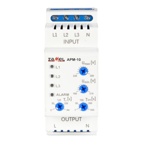
Zamel exta APM-10 User manual

Zamel

Zamel exta APM-10 User manual

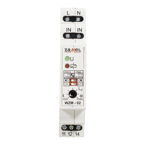
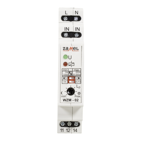
Zamel TWILIGHT SWITCH WZM-02 User manual

Zamel

Zamel TWILIGHT SWITCH WZM-02 User manual

Zamel YNSTA PDJ-213 User manual

Zamel

Zamel YNSTA PDJ-213 User manual

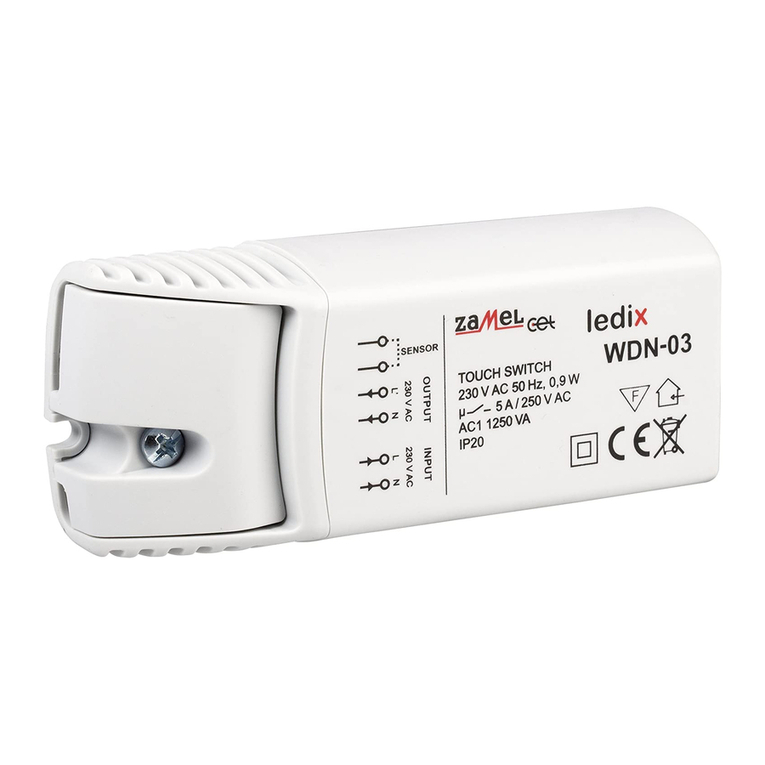
Zamel Ledix WDN-03 User manual

Zamel

Zamel Ledix WDN-03 User manual

Zamel Ynsta PDJ-213P User manual

Zamel

Zamel Ynsta PDJ-213P User manual

Zamel exta WZH-01 User manual

Zamel

Zamel exta WZH-01 User manual

Zamel GRG-01 User manual

Zamel

Zamel GRG-01 User manual

Zamel EXTA WZM-02 User manual

Zamel

Zamel EXTA WZM-02 User manual

Zamel stiro RWS-211D/N User manual

Zamel

Zamel stiro RWS-211D/N User manual

Zamel exta WZM-01 Series User manual

Zamel

Zamel exta WZM-01 Series User manual

Zamel EXTA APM-20 User manual

Zamel

Zamel EXTA APM-20 User manual

Zamel GRM-10 User manual

Zamel

Zamel GRM-10 User manual

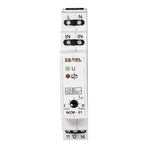
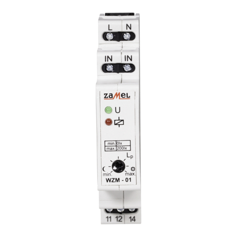
Zamel WZM-01 User manual

Zamel

Zamel WZM-01 User manual

Zamel WZM-01/SOS User manual

Zamel

Zamel WZM-01/SOS User manual

Zamel RWS-311D/Z User manual

Zamel

Zamel RWS-311D/Z User manual

Zamel stiro RWS-211J/N User manual

Zamel

Zamel stiro RWS-211J/N User manual

Zamel RWS-311D User manual

Zamel

Zamel RWS-311D User manual

Zamel RWS-311D/Z User manual

Zamel

Zamel RWS-311D/Z User manual

Zamel GRL-01 User manual

Zamel

Zamel GRL-01 User manual

Popular Switch manuals by other brands

Exsys EX-1170HMVS manual

Exsys

Exsys EX-1170HMVS manual

DeLOCK 87762 user manual

DeLOCK

DeLOCK 87762 user manual

Gefen EXT-MINIDVI-241N user manual

Gefen

Gefen EXT-MINIDVI-241N user manual

WEIGL ProCommander 2 Wiring diagram

WEIGL

WEIGL ProCommander 2 Wiring diagram

Aluprof DC1690 Programming manual

Aluprof

Aluprof DC1690 Programming manual

Enabling Devices 7459 user guide

Enabling Devices

Enabling Devices 7459 user guide

Ihse Draco U-Switch user manual

Ihse

Ihse Draco U-Switch user manual

Avocent SwitchView Quick installation guide

Avocent

Avocent SwitchView Quick installation guide

Eaton Cutler-Hammer ATVSKDA30300XSU instructions

Eaton

Eaton Cutler-Hammer ATVSKDA30300XSU instructions

LogiLink UA0091 user manual

LogiLink

LogiLink UA0091 user manual

DeLOCK 11826 user manual

DeLOCK

DeLOCK 11826 user manual

NETGEAR GS305v3 installation guide

NETGEAR

NETGEAR GS305v3 installation guide

MLC LS10 instruction manual

MLC

MLC LS10 instruction manual

Orbis MULTIMAT Instructions for use

Orbis

Orbis MULTIMAT Instructions for use

Amphenol RJSMLAC 8MG CAPS Hardware user manual

Amphenol

Amphenol RJSMLAC 8MG CAPS Hardware user manual

StarTech.com ST4202USB instruction manual

StarTech.com

StarTech.com ST4202USB instruction manual

Barksdale CSK Installation instructions manual

Barksdale

Barksdale CSK Installation instructions manual

Siemens S 563 quick start guide

Siemens

Siemens S 563 quick start guide

manuals.online logo
manuals.online logoBrands
  • About & Mission
  • Contact us
  • Privacy Policy
  • Terms and Conditions

Copyright 2025 Manuals.Online. All Rights Reserved.