manuals.online logo
Brands
  1. Home
  2. •
  3. Brands
  4. •
  5. Zamel
  6. •
  7. Switch
  8. •
  9. Zamel exta APM-10 User manual

Zamel exta APM-10 User manual

AUTOMATIC PHASE SWITCH APM-10
USER’S MANUAL
ZAMEL Sp. z o.o.
ul. Zielona 27, 43-200 Pszczyna, Poland
tel. +48 (32) 210 46 65, fax +48 (32) 210 80 04
www.zamel.com, e-mail: [email protected]
plik: apm-10_inst_ext_gb | modykacja: 12.03.2021
APPEARANCE
FEATURES
TECHNICAL DATA
DESCRIPTION
● Ensuring continuity of supply to a single-
phase load,
● three-phase supply L1-L2-L3 (L1-priority
phase),
● adjustment of the response threshold for
maximum voltage,
● adjustment of the response threshold for
minimum voltage,
● adjustment of the priority phase reset time,
● adjustment of the auto reset time,
● output load capacity - max. 16A for C1
loads,
● parameter signaling for individual supply
phases - 3 x LEDs,
● fault indication,
● mounting in the switchgear (DIN-Rail).
APM-10 Automatic phase switch is a de-
vice designed to maintain continuity of power
supply to a single-phase load at the time of
voltage uctuation in the network. The device
automatically selects the closest priority phase
within the user-dened setting range and con-
nects it to the single-phase load. The maxi-
mum load capacity of the output should not
exceed 16A for loads in class AC1. APM-10 is
designed for installations in switchgears (DIN-
Rail). The housing has the width of 2 modules.
Power supply terminals: L1, L2, L3, N
Rated supply voltage: 3 x 230 V AC + N
Rated frequency: 45 ÷ 55 Hz
Response range at Umin: 160 ÷ 210 V
Response range at Umax: 230 ÷ 280 V
Priority phase output reclosing time range Tr*: 5 ÷ 200 s
Reclosing time adjustment range Ton: 1 ÷ 600 s
Fixed switching delay (disconnection) at Umin: 12 s
Backup phase switching time: no longer than 0.2 s
Voltage hysteresis: 5 ÷ 6 V
Accuracy of determining response threshold at voltage change: ±3 V
Maximum commutated current (cos φ=1) of output contacts: 16 A
Maximum commutated current (cos φ=0.4) of output contacts: 5 A
Power consumption (under load): not greater than 1,2 W
Number of connection terminals: 8
Cross section of connection wires: 0,5 ÷ 1,5 mm2
Operating temperature: -20 ÷ +45 °C
Working position: free
Housing mounting: DIN-Rail
Housing protection degree: IP20
Overvoltage category: II
Pollution degree: 2
Dimensions: 90,2x36x64,5
Weight: 0,15 kg
The device should be con-
nected to a one-phase network
in accordance with legally bind-
ing standards. The connection
method is described in this
manual. Any activities related
to installation, connection, and adjustment
should be performed by qualied electricians
who have read this user’s manual and famil-
iarised themselves with device functions. Re-
moving the enclosure voids the warranty and
poses a risk of electric shock. Before instal-
lation, make sure that there is no voltage on
connection cables. To install the device, use
a cross-head screwdriver with a diameter of
3.5 mm. The proper operation of the device
is affected by how the device is transported,
stored, and used. It is not advisable to install
the device in the following cases: lack of any
components, damage to or deformation of
the device. If the device operates improperly,
please contact the manufacturer.
NOTE
Do not dispose of this device together
with other waste! To avoid harmful effects
on the environment and human health,
the worn-out device should be stored
in designated areas. Electrical waste
from households may be handed over
to the waste collector established for
this purpose free of change and in any
amount, as well as to the store when
purchasing new equipment.
Signalling the parameters
of voltage supply phases
Signalling the faults
Regulation of the response
threshold for maximum voltage Umax
Regulation of the response
threshold for minimum voltage Umin
Regulation of time for automatic
restart Тon
Regulation of time of re-activation
of the priority phase on output Tr
Output terminals
(for load connection)
Power supply terminals
CONNECTION
OPERATION
ASSEMBLY
1. Disconnect the power supply circuit with
a fuse, an overcurrent circuit breaker or isola-
tor switch-disconnector combined to the cor-
responding circuit.
2. Check voltage-free condition on supply con-
ductors using proper measuring instrument.
3. Mount the APM-10 in the switchgear on the
DIN-Rail rail
4 . Connect the wires to the terminals in accord-
ance with the wiring diagram.
5. Set the response thresholds of the device us-
ing the potentiometers: Umax, Umin, Тr i Тon.
NOTE! During operation, the values of Umax,
Umin, Trand Ton can be changed, provided
that the safety rules are observed.
6. Switch on the power supply.
7. Check if the device operates properly.
WARRANTY CARD
Manufacturer provides a 24-month warranty
Seller’s stamp and signature, date of sale
1. ZAMEL Sp. z o.o. shall offer a 24-month warranty on the products sold.
2. The warranty provided by ZAMEL Sp. z o.o. shall not cover:
a) mechanical damage caused during transport, loading/unloading or in other circumstances,
b) damage caused by incorrect installation or operation of products manufactured by ZAMEL Sp. z o.o.,
c) damage resulting from any changes made by the BUYER or third parties in the products sold or equipment necessary for the
proper operation of the products sold,
d) damage resulting from force majeure or other fortuitous events for which ZAMEL Sp. z o.o. is not liable.
3. Any warranty claims shall be made by the BUYER at the point of sale or to ZAMEL z o.o. in writing after defects have been identi-
ed.
4. ZAMEL Sp. z o.o. undertakes to handle complaints in accordance with the applicable provisions of Polish law.
5. The choice of the form of complain resolution, e.g. replacement of a product with a product free from defects, repair, or reimburse-
ment of money, shall lie with ZAMEL Sp. z o.o.
6. The warranty does not exclude, limit, or suspend BUYER’s rights under the statutory warranty for defects in the item sold.
The APM-10 electronic phase switch is a microprocessor-based digital device. The user sets response thresholds for the minimum and maximum voltage
values at which the phase switch activates and switches the reserve phase (disconnects the load). The lighting of one of the green LEDs L1, L2, L3 on the
front panel indicates the phase to which the load is connected.
With the correct voltage on all phases (L1, L2, L3), the load will be connected to phase L1. If the voltage value on L1 exceeds the threshold, APM-10 will
check the L2 phase and connect the load to it. If the voltage on L2 exceeds the response thresholds, the APM-10 will connect the load to the L3 phase.
When the voltage on the reserve phases exceeds the set thresholds, the load is disconnected.
NOTE! Switching to a phase with incorrect parameters is not possible.
After switching to the reserve phase and restoring the correct voltage parameters on the priority phase, the load will be switched to the priority phase after
the user-set recovery time.
NOTE! If the voltage on the priority phase exceeds the thresholds during the recovery time countdown, the timer will restart.
If Tr is set to „∞”, the priority phase is switched back to the output only if the voltage on the reserve phase exceeds the set thresholds.
If the voltage applied to the load falls below the minimum allowable voltage, the load is switched on or off with a time delay of 12 seconds. If the voltage
value rises above the maximum allowable voltage threshold or drops 30 V below the minimum allowable voltage threshold, the load is switched or discon-
nected with a time delay of 0.2 s.
When the load is disconnected, the APM-10 continues to monitor the voltage on all phases.
When the voltage on one of the phases is restored to acceptable parameters, the APM-10 will connect a load to that phase within the Ton timeout.
If the load is disconnected on all three phases, the „ALARM” LED will light up. When the voltage on all three phases exceeds the preset response thresh-
olds, the load will be disconnected and the „ALARM” LED will light up. If several APM-10 phase switches are used in a network, it is recommended to select
different phases for different groups of consumers as „priority” in order to prevent overloading of the phases.
Timing chart: Internal Circuitry
L2
L3
OUT
OUT
OFF
OUT
OFF
L1
PK1 PK2 PK3
L1L2 L2 L1L3 L3
L1
Umin
Umin
Umin
Umin
Umax
Umax
Umax
max 0,2 s TrTon Ton
L1
L2
L3
N

Other Zamel Switch manuals

Zamel WZM-01/SOS User manual

Zamel

Zamel WZM-01/SOS User manual

Zamel GRM-10 User manual

Zamel

Zamel GRM-10 User manual

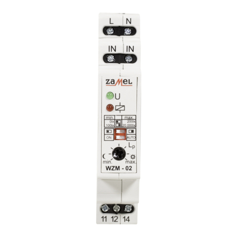
Zamel TWILIGHT SWITCH WZM-02 User manual

Zamel

Zamel TWILIGHT SWITCH WZM-02 User manual

Zamel EXTA APM-20 User manual

Zamel

Zamel EXTA APM-20 User manual

Zamel exta WZM-01 Series User manual

Zamel

Zamel exta WZM-01 Series User manual

Zamel RWS-311D User manual

Zamel

Zamel RWS-311D User manual

Zamel EXTA WZM-02 User manual

Zamel

Zamel EXTA WZM-02 User manual

Zamel GRL-01 User manual

Zamel

Zamel GRL-01 User manual

Zamel Ledix WDN-01 User manual

Zamel

Zamel Ledix WDN-01 User manual

Zamel YNSTA PDJ-213 User manual

Zamel

Zamel YNSTA PDJ-213 User manual

Zamel stiro RWS-211D/N User manual

Zamel

Zamel stiro RWS-211D/N User manual

Zamel RWS-311D/Z User manual

Zamel

Zamel RWS-311D/Z User manual

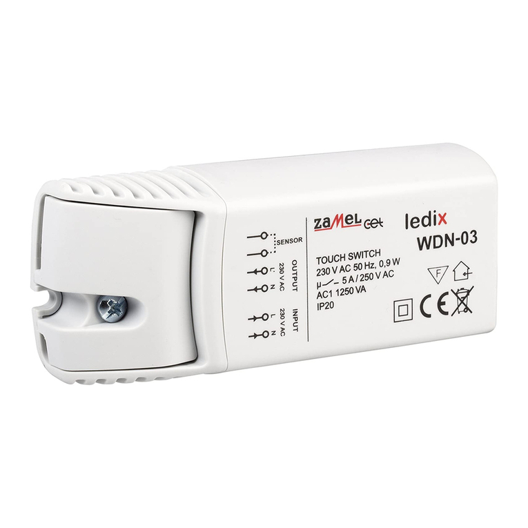
Zamel Ledix WDN-03 User manual

Zamel

Zamel Ledix WDN-03 User manual

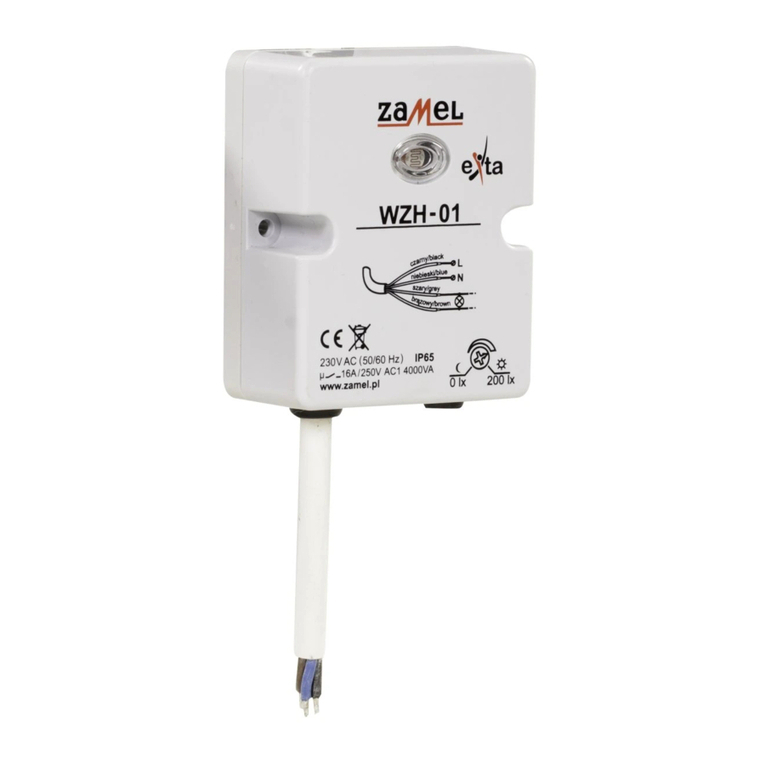
Zamel exta WZH-01 User manual

Zamel

Zamel exta WZH-01 User manual

Zamel RWS-311D/Z User manual

Zamel

Zamel RWS-311D/Z User manual

Zamel Ynsta PDJ-213P User manual

Zamel

Zamel Ynsta PDJ-213P User manual

Zamel stiro RWS-211J/N User manual

Zamel

Zamel stiro RWS-211J/N User manual

Zamel GRG-01 User manual

Zamel

Zamel GRG-01 User manual

Zamel WZM-01 User manual

Zamel

Zamel WZM-01 User manual

Popular Switch manuals by other brands

Blue Sea Systems 6006 manual

Blue Sea Systems

Blue Sea Systems 6006 manual

TP-Link TL-SG105 Mounting guide

TP-Link

TP-Link TL-SG105 Mounting guide

Rehabmart Rocket Switch user guide

Rehabmart

Rehabmart Rocket Switch user guide

Cisco 3750G - Catalyst Integrated Wireless LAN... Getting started guide

Cisco

Cisco 3750G - Catalyst Integrated Wireless LAN... Getting started guide

3Com CoreBuilder 2500 Software Installation and Release Notes

3Com

3Com CoreBuilder 2500 Software Installation and Release Notes

Bryston SWB2 Hookups and settings

Bryston

Bryston SWB2 Hookups and settings

Renkforce RF-4821051 operating instructions

Renkforce

Renkforce RF-4821051 operating instructions

schmersal AZM300B-I2-ST-1P2P instructions

schmersal

schmersal AZM300B-I2-ST-1P2P instructions

Siemens RUGGEDCOM RS910W installation manual

Siemens

Siemens RUGGEDCOM RS910W installation manual

Comnet CNGE2FE8MSPOE2 Installation and operation manual

Comnet

Comnet CNGE2FE8MSPOE2 Installation and operation manual

Rose electronics Video Easyware Installation and operation

Rose electronics

Rose electronics Video Easyware Installation and operation

INSTEON Assurance Kit quick start guide

INSTEON

INSTEON Assurance Kit quick start guide

Vigitron MaxiiNet Vi3005 installation manual

Vigitron

Vigitron MaxiiNet Vi3005 installation manual

Edimax EK-08RE Declaration of conformity

Edimax

Edimax EK-08RE Declaration of conformity

Cypress CLUX-C61C Operation manual

Cypress

Cypress CLUX-C61C Operation manual

Lancom GS-2310 Quick reference guide

Lancom

Lancom GS-2310 Quick reference guide

Siemens SCALANCE X-300 Compact operating instructions

Siemens

Siemens SCALANCE X-300 Compact operating instructions

Extricom EXSW800 user guide

Extricom

Extricom EXSW800 user guide

manuals.online logo
manuals.online logoBrands
  • About & Mission
  • Contact us
  • Privacy Policy
  • Terms and Conditions

Copyright 2025 Manuals.Online. All Rights Reserved.