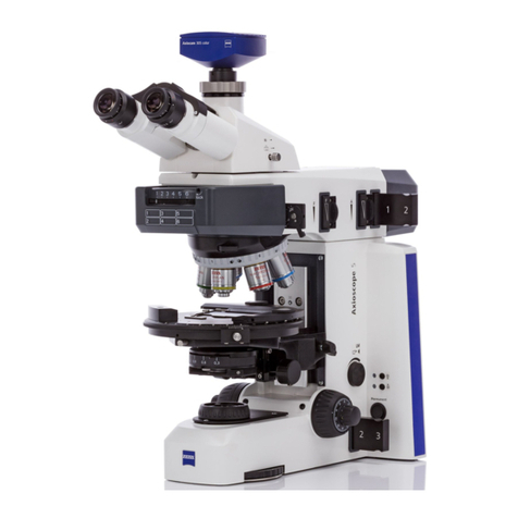
Axiolab A Carl Zeiss
B 40-015 e 06/99 V
LIST OF ILLUSTRATIONS
Page
Fig. 1-1 Axiolab A main modules ..................................................................................................1-3
Fig. 1-2 Optical design of the Axiolab A with transmitted-light equipment.....................................1-4
Fig. 1-3 Axiolab A microscope configurations................................................................................1-6
Fig. 1-4 Axiolab A accessories..............................................................................................1-8, 1-10
Fig. 1-5 Axiolab A function elements .................................................................................1-16, 1-17
Fig. 2-1 Unpacking the instrument................................................................................................2-3
Fig. 2-2 Screw in objectives ..........................................................................................................2-3
Fig. 2-3 Insertion of eyepiece reticle..............................................................................................2-4
Fig. 2-4 Attachment of reflected-light halogen illuminator.............................................................2-6
Fig. 2-5 Equipment of filter slider..................................................................................................2-7
Fig. 2-6 Setting the luminous-field diaphragm...............................................................................2-8
Fig. 2-7 Connecting the instrument to the line..............................................................................2-9
Fig. 3-1 Switch on the instrument.................................................................................................3-3
Fig. 3-2 Setting of reflected-light brightfield..................................................................................3-4
Fig. 3-3 Setting of reflected-light polarization ...............................................................................3-5
Fig. 3-4 Centering of objectives ....................................................................................................3-6
Fig. 3-5 Setting of transmitted-light polarization ...........................................................................3-7
Fig. 3-6 Determine the nγ'vibration direction using the example of an artificial fiber......................3-8
Fig. 3-7 Schematic diagram of the color chart in addition and subtraction position ........................3-8
Fig. 3-8 Determine the optical character of crystals .....................................................................3-11
Fig. 3-9 Setting of epi-fluorescence.............................................................................................3-13
Fig. 3-10 Setting of transmitted-light brightfield ...........................................................................3-14
Fig. 3-11 Stage selection ..............................................................................................................3-15
Fig. 3-12 Changing the microscope stage .....................................................................................3-15
Fig. 3-13 Pol rotary stage- setting of specimen mount and stop ....................................................3-16
Fig. 3-14 Use of polished section attachment................................................................................3-17
Fig. 3-15 Attach various camera systems to the Axiolab A phototube ............................................3-18
Fig. 3-16 Attachment of SLR camera, e.g. CONTAX 167 MT .........................................................3-19
Fig. 3-17 Attachment of MC 80 DX...............................................................................................3-21
Fig. 3-18 Insertion of 8×drawing eyepiece....................................................................................3-24
