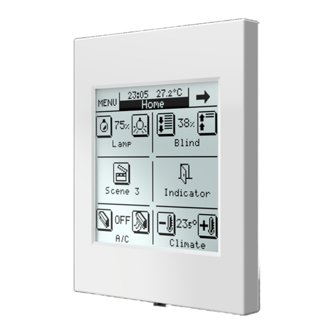
Zennio InZennio Z38i User manual

INZENNIO Z38i
KNX Touch Panel
ZN1VI-TP38i
Edition 2.1
Version 2.1
PRODUCT MANUAL

ZENNiO AVANCE Y TECNOLOGÍA www.zennio.com
2
INDEX
1. INTRODUCTION.................................................................................................................4
1.1. PRODUCT...................................................................................................................4
1.2. INSTALLATION...........................................................................................................7
2. ETSCONFIGURATION........................................................................................................7
2.1. DEFAULTCONFIGURATION........................................................................................7
2.2. GENERAL...................................................................................................................9
2.2.1. DISPLAYLIGHTING.............................................................................................9
2.2.2. STARTUP INDICATORS UPDATE........................................................................10
2.2.3. HEADER...........................................................................................................10
2.2.4. PAIR BUTTON WORKING MODE.......................................................................11
2.2.5. REMOTE CONTROLLER.....................................................................................12
2.2.6. TEMPERATURE SENSORCALIBRATION..............................................................12
2.2.7. TEMPERATURE SENDINGPERIOD.....................................................................13
2.2.8. PASSWORD......................................................................................................13
2.3. PAGES......................................................................................................................14
2.3.1. HOME AND HOME2 PAGES .............................................................................15
2.3.1.1. BINARYCONTROL.....................................................................................16
2.3.1.2. LIGHTCONTROL.......................................................................................17
2.3.1.3. SHUTTERCONTROL..................................................................................19
2.3.1.4. CLIMATE CONTROL...................................................................................20
2.3.1.5. 1BYTECONTROL......................................................................................21
2.3.1.6. SCENECONTROL.......................................................................................22
2.3.1.7. TEMPERATURECONTROL.........................................................................24
2.3.1.8. BINARYINDICATOR ..................................................................................25
2.3.1.9. 1BYTEINDICATOR....................................................................................25
2.3.1.10. FLOATINGINDICATOR...................................................................................26
2.3.1.11. SECURITY CONTROL ......................................................................................27
2.3.1.12. PRESENCESIMULATOR..................................................................................27
2.3.2. SPECIFIC PAGES................................................................................................29
2.3.2.1. SCENES.....................................................................................................29
2.3.2.2. TIMERS.....................................................................................................30
2.3.2.3. CLIMATE...................................................................................................33
ZENNiO AVANCE Y TECNOLOGÍA www.zennio.com
3
2.3.3. TECHNICALALARMS.........................................................................................38
2.3.4. CONFIGURATION .............................................................................................40
2.4. INPUTS....................................................................................................................43
2.4.1. PUSH BUTTON .................................................................................................43
2.4.1.1. SHORTPRESS............................................................................................44
2.4.1.2. LONGPRESS.............................................................................................46
2.4.1.3. THRESHOLD TIME.....................................................................................46
2.4.1.4. RESPONSE DELAY .....................................................................................47
2.4.1.5. BLOCK......................................................................................................47
2.4.2. SWITCH/SENSOR..............................................................................................47
2.4.2.1. RISING EDGE ............................................................................................48
2.4.2.2. FALLINGEDGE..........................................................................................48
2.4.2.3. SENDING OF "0" DELAY ............................................................................48
2.4.2.4. SENDING OF "1" DELAY ............................................................................48
2.4.2.5. PERIODICALSENDING "0".........................................................................48
2.4.2.6. PERIODICALSENDING "1".........................................................................49
2.4.2.7. BLOCK......................................................................................................49
2.5. THERMOSTAT..........................................................................................................50
3. ANNEX I. COMMUNICATION OBJECTS .............................................................................51

ZENNiO AVANCE Y TECNOLOGÍA www.zennio.com
4
1. INTRODUCTION
1.1. PRODUCT
InZennio Z38i is an LCD Touch Panel with Room Thermostat, Binary Inputs
and IR Receiver built-in.Some of its most important features are mentioned below:
KNX 3.8” back-lighted monochrome Touch Panel
2 independent thermostats configuration
Presence simulation
Full Climate Management
12 Configurable Direct Control Functions
5 Additional Pages with up to 6 independent functions:
Scene Control [5 Functions]
Schedule Programming [4 Functions]
Climate Control [6 Functions]
Technical Alarms [6 Functions]
Display Parameters
IR Receiver built-in (Remote Control)
4 Binary Inputs for Voltage free push buttons or
switch/sensors
KNX BCU included
The Touch Panel InZennio Z38i is organized into "Pages"; every page consists
of several parametrizable boxes and a header.
Depending on the boxes configuration, it may be possible to associate them an
individual control (or a pair of controls) and/or indicators, in order to better identify the
function to carry out. Please refer to the specific documentation “Controls and
Indicators of InZennio Z38i Touch panel”.

ZENNiO AVANCE Y TECNOLOGÍA www.zennio.com
5
Figure 1.1 shows schematically the screen organization of Touch Panel
InZennio Z38i.
The next schema represents available pages to be “enabled” and its hierarchy.
Figura 1.1. Schematic page organization
HOME PAGE
MENU PAGE
Specific pages access
HOME 2 PAGE
-SCENES
1
- SCH. PROGRAMMING
- CLIMA
- SCENES
2
- SCH. PROGRAMMING
- CLIMA
- SCENES
3
- SCH. PROGRAMMING
-
CLIMA
- SCENES
4
- SCH. PROGRAMMING
-
CLIMA
TECHNICAL
ALARMS 5 CONFIGURATION
6
5
Header
HOME PAGE
MENU Page shortout HOME 2 shortout
IR Receiver Sensor
PARAMETRIZABLE
BOX

ZENNiO AVANCE Y TECNOLOGÍA www.zennio.com
6
Next sections in this manual will detail the correct way to configure and program
the LCD Panel InZennio Z38i, so that a user can control all (or part of) the KNX
installation from a single device.
<<PAGES>>
Home 1 / Home 2
The “Home” page is the InZennio Z38i “Welcome” page; this will be the
starting point (once the necessary boxes have been enabled) to access,
the most commonly required functions.
The "Home 2" page is just like the "Home" one, as far as functionality and
potential programming terms is concerned. The "Home 2" page is an
extension of the own "Home" page.
MENU PAGE: Access to specific pages.
In this case, it is possible to "enable" up to six different pages, and
even, when talking about the "Specific 1, 2, 3 & 4" ones, to associate
them with a particular function:
Scenes
Timers

ZENNiO AVANCE Y TECNOLOGÍA www.zennio.com
7
Climate
Note: "Home", "Home 2", and the "Technical Alarms" and “Climate” pages
in the InZennio Z38i panel have 6 parametrizable boxes each; "Scenes", and
the "Configuration" pages have 5 parametrizable boxes each, while the
“Timers”page have4 parametrizable boxes.
1.2. INSTALLATION
To obtain an information ever more detailed about the technical features of
InZennio Z38i panel, as well as security and installation information, please read the
device Datasheet, included in the original package of the device and also available at:
http://www.zennio.com.
2. ETS CONFIGURATION
To begin with the panel configuration it is necessary to import in ETS a project
that contains an InZennio Z38i module of the device or a database .vd file of the
product.
This manual starts from the "default" product configuration, to gradually
configure the device according to the user requirements.
2.1. DEFAULT CONFIGURATION
This section shows the default configuration from which the device
parameterization starts.
When entering for the first time to the parameters edition of InZennio Z38i, the
following window will be shown:

ZENNiO AVANCE Y TECNOLOGÍA www.zennio.com
8
Figure 2.1. Parameterization screen by default
From this window, the different options can be parameterized. They will be
explained in the following sections:
General: to configure the general options of the panel and IR control.
Pages: to enable and customize each of the functioning windows:
Home 1, Home 2 and specific pages.
Inputs: to enable and configure up to 4 inputs in the panel.
Thermostats: to enable and configure up to 2 thermostats.

ZENNiO AVANCE Y TECNOLOGÍA www.zennio.com
9
2.2. GENERAL
This parameterization section allows configuring the general options of the
panel and its remote control.
Each available option is described below:
2.2.1. DISPLAY LIGHTING
Always lighting: light on the display remains always ON, even when
the page is not in use.
Automatic luminosity attenuation: 45 seconds after the last
interaction on the display, this will recover its stand-by mode. These
options are shown:
Luminosity attenuation level
Completely Dark: After 45 seconds (Auto Dimming), the
own auxiliary light on the display will remain OFF (until a
new touch on it is made).
Low Luminosity: After 45 seconds (Auto Dimming), the
display will light slightly, (this is useful to identify it in dark
places).
Status during attenuation
Display enabled: Display remains always active; this means
that any interaction with it will obtain an immediate
response.
Display Disabled (touch anywhere to unblock): The display
needs a first touch onto it to be unlocked, after this, this can
be normally operated.
The options related to the display lighting are shown in the next schema (Figure
2.2).

ZENNiO AVANCE Y TECNOLOGÍA www.zennio.com
10
Figure 2.2. Display lighting options
2.2.2. STARTUP INDICATORS UPDATE
When recovering the bus voltage (or after a program download), the InZennio
Z38i may ask the rest of devices in the installation for their corresponding
values, in order to update the display indicators. If this option is enabled ("Yes"),
the "Delay" field appears, where to parameterize the time, in seconds, the panel
waits until the rest of devices on the installation are completely initiated.
2.2.3. HEADER
It is possible to select by parameter whether to show or not in the display
header the temperature, the time and the date.

ZENNiO AVANCE Y TECNOLOGÍA www.zennio.com
11
If "Show Date" is enabled ("Yes"), it appears a new field to indicate through 7
characters the weekday initials. Only capital letters and numbers can be used.
Both the date and the week-day will appear on any page header, when the
“Time Zone” is pressed.
Note: Weeks days are automatically calculated by the own display when
adjusting the date on it.
2.2.4. PAIR BUTTON WORKING MODE
This parameter allows selecting the way the pair buttons (in the individual boxes
where its use is configured) will work, choosing between:
Left: off/down; Right: on/up.
With this configuration, the pair button on the left of the box will send the
order to switch off, move down, last and lower, whereas the right button
will send the orders to switch on, move up, next and rise, depending on
the type of the pair buttons.
Left: on/up; Right: off/down.
With this configuration, the pair button on the left of the box will send the
order to switch on, move up, next and rise, whereas the right button will
send the orders to switch off, move down, last and lower, depending on
the type of the pair buttons.
Note: The boxes of the Home and Home 2 pages configured as “Binary control”
this working mode configuration is not taken into account, since they will carry
out the order specified by parameter.
Date - (M) Monday
Time Zone

ZENNiO AVANCE Y TECNOLOGÍA www.zennio.com
12
2.2.5. REMOTE CONTROLLER
This parameter allows enabling the zones of the remote controller and
associate each of them to either any of both Home 1 or Home 2 pages, to
control them remotely.
Zone 1: To enable and associate this IR controller zone to any of the
Home or Home 2 pages.
Zone 2: To enable and associate this IR controller zone to any of the
Home or Home 2 pages.
Note I: Buttons arrangement on the remote controller is similar to the “Home &
Home 2” boxes structure to make its control easier.
Note II: If remote controller is disabled in the parameterization, a press key over
any button DOES NOT have effect in the touch panel.
2.2.6. TEMPERATURE SENSOR CALIBRATION
Allow recalibrating the Temperature Sensor referred to the own temperature
measured by the sensor itself when the calibration parameter remains
unchanged (value “0”).
Zone 1
Zone 2

ZENNiO AVANCE Y TECNOLOGÍA www.zennio.com
13
2.2.7. TEMPERATURE SENDING PERIOD
This field is meant to set a period of time for the Z38i to send the registered
temperature to the bus through the “Temperature” Communication object.
If a 0 value is set, the temperature will not be sent.
2.2.8. PASSWORD
With this option, it will be possible to configure a customizable password, by
establishing 4 digits from 0 to 9, which must be written to access those pages
on which security was enabled.
Default password is 1234.
In the field "Allow password changing", one can choose whether the password
can be modified in the panel itself or not. If this change is not allowed, the
password can only be changed through ETS (parameters).
If the password changing is enabled, the following steps must be carried out to
properly change it (see also figure 2.3):
1.- Press NEW.In the upper part of the box the word “OLD” will appear
and the old password has to be written.
2.- After introducing it correctly, the word “NEW” will appear. That is the
moment to insert the new password.
3 - "REPEAT". Insert again the desired new password.
The left arrow button allows deleting/cancelling, in case of wrong-typing the
digits.

ZENNiO AVANCE Y TECNOLOGÍA www.zennio.com
14
Figure 2.3. Password changing from the panel
2.3. PAGES
This parameterization section details the enabling and configuration of the
different pages of the InZennio Z38i, including the submenus they offer.
Figure 2.4. Pages configuration
Every enabled page has some parametrizable fields:

ZENNiO AVANCE Y TECNOLOGÍA www.zennio.com
15
Name: This field allow users to associate a name to any of the InZennio
Z38i pages; this name will appear on any of the page headers the user
is moving through (12 free characters are available to set the name).
Note: The only page which cannot be renamed is the MENU one (to access
Specific Pages).
Security: A restricted page prevents unauthorized access to it. 4 digits
password is required to enter a protected page (see Section 2.2.8).
Note: The “Home” page is enabled by default. Access to the “Home” page
cannot be restricted.
2.3.1. HOME AND HOME 2 PAGES
These two pages are intended to parameterize their boxes so that a user can
easily access the most common used functions when controlling an installation.
As well as the pages, every box on “Home” and “Home 2" pages has a
parametrizable field:
Name: This field allows a user to associate a name with the
corresponding box in the page. (11 free characters are available to set
the name).
Note: “Home” Page will be shown again 90 seconds after last interaction on the
display took place.
The field "Security" only appears for Home 2 page. The “Home” page is enabled
by default. Access to the “Home” page cannot be restricted.
Both pages have 6 customizable boxes, to be configured as: binary control,
light control, shutter control, climate control, 1 byte control, scene
control, temperature control, binary indicator, 1 byte indicator, floating
indicator, security control and presence simulator.
Every configuration is explained below.

ZENNiO AVANCE Y TECNOLOGÍA www.zennio.com
16
Figure 2.5. Home 1 page, with its 6 boxes with different configurations
2.3.1.1. BINARY CONTROL
This is a generic control to communicate all those devices susceptible to
be, by sending a single bit (“0” or “1”).
The following options will appear:
Button 1 Always enabled by default.
Short press: By pressing this button, one the following
values will be sent to the bus, through the object "[Home
x Box y] Binary control": Nothing, "0", "1" or Toggle

ZENNiO AVANCE Y TECNOLOGÍA www.zennio.com
17
(changing the value of the receiver associated of the
communication object).
Long press: Same case than before, the only difference
is that now users will need to keep the button on the
display pressed during at least 0.5 seconds to send the
corresponding data through its Communication Object.
Icon: An icon can be associated to the page box.
Button 2 It might be possible to have two buttons on the same
BOX, by simply activating this option in the corresponding field.
Although both buttons will transmit data independently; both of them
also share the same Communication Object.
The way to parrameterize this button is exactly the same as for
Button 1.
Indicator By activating this parameter, a status indicator will be
inserted between both buttons.
2.3.1.2. LIGHT CONTROL
This control is specifically designed for lighting control. Through its
associated communication objects ("Light On/Off", "Light Dimming" and
"Precise dimming") users will be able to turn On/Off any kind of
incandescent lamps, low voltage lamps, compact fluorescent lamps, etc.,
and even controlling their output intensity.
Note: When trying to control compact fluorescent lamps (CFL), an
electronically reactance or a specific KNX actuator would be necessary to
control their intensity.

ZENNiO AVANCE Y TECNOLOGÍA www.zennio.com
18
Type This field allows the user to choose the control type:
ON/OFF: This is the most basic control type. The user
can select an indicator to show the ON/OFF light status.
On/Off + Simple Regulation (4 bits): Users can
simulate a common switch action, turn On/Off (short press
on the buttons), or a discreet regulation (long press on the
buttons), where depending on the “dimming step” set,
keeping the button pressed will reduce or increase the
brightness on the controlled lamps.
Dimming step: Seven different regulation levels are
available for this duty. A long press on the display buttons
will reduce or increase the brightness level step by step
the percentage set in this parameter; once the desired
level is reached, stop pressing the button on the display
to keep the desired value. To know the available dimming
steps, please see figure 2.6.
Indicator: This will inform users about the brightness
percentage applied at any time.
Note: In this case, for this indicator to be functional, it is necessary to use a KNX
dimmer to give back the brightness applied to the load.

ZENNiO AVANCE Y TECNOLOGÍA www.zennio.com
19
Dimming step Necessary pulsations for a complete
regulation (0-100%)
(1). 100% 1
(2). 50% 2
(3). 25% 4
(4). 12.5% 8
(5). 6.25% 16
(6). 3.1% 32
(7). 1.5% 64
Figure 2.6. Dimming step
Precise dimming (1 byte): This is the most accurate
control method, as any short press on the display buttons
will increase or reduce (1%) the brightness level. A long
press on any of the two buttons will increase or reduce
gradually 10 % the brightness level.
Indicator: This will inform users about the brightness
percentage applied at any time.
Icon An icon can be associated to the page box.
2.3.1.3. SHUTTER CONTROL
Specifically designed to control any type of shutters, blinds, sun blinds, or
any other drive. Through its communication objects, users will be able to
raise / lower shutters ("Move shutter" and "Stop shutter") and even knowing
its exact position at any time ("Shutter Position").
The basic shutter control is made as follows:

ZENNiO AVANCE Y TECNOLOGÍA www.zennio.com
20
Long press: Move shutter.
Raise Shutter: 0” is sent trough the object “Move Shutter”.
Lower Shutter: “1” is sent trough the object “Move Shutter”.
Note: When the object “Move Shutter” sends “0” or “1”, the shutter will start
moving, and won’t stop unless the whole shutter length is covered or that
any other order cancelling the previous is received.
Short press: Stop shutter.
To stop a moving shutter, a “0” or a “1” must be sent through the
object “Stop Shutter”.
Icon An icon can be associated to the page box.
Indicator By activating this parameter, users can insert an indicator
between both buttons to get estimation in percentage terms of the shutter
position.
2.3.1.4. CLIMATE CONTROL
Designed specifically to control the functioning of air conditioning devices
without the need to access a specific climate page.
This can be very useful if there are free boxes in “Home” or “Home II”
pages because that way, the user will avoid browsing between the different
pages and will have access directly to determinate specific functions. It is
possible to access to this (depending on the configuration applied to the
function):
Control typeChoose the specific climate function to control:
Other manuals for InZennio Z38i
3
Table of contents
Other Zennio Touch Panel manuals

Zennio
Zennio Z41 Pro User manual

Zennio
Zennio Z41 Pro Guide

Zennio
Zennio Z70 v2 User manual

Zennio
Zennio FLAT User manual

Zennio
Zennio FLAT 55 User manual

Zennio
Zennio Touch-MyDesign ZN1VI-TPTMD4 User manual

Zennio
Zennio Z35 User manual

Zennio
Zennio Z41 Pro User manual

Zennio
Zennio Z41 Guide

Zennio
Zennio Z41 COM User manual

Zennio
Zennio Z41 Pro Guide

Zennio
Zennio Z41 User manual

Zennio
Zennio ZVI-SQTMDD User manual

Zennio
Zennio Z41 Pro Guide

Zennio
Zennio Z41 Pro User manual

Zennio
Zennio ZVI-SQTMD1 User manual

Zennio
Zennio ZN1VI-TP41C User manual

Zennio
Zennio Touch-MyDesign Display One User manual

Zennio
Zennio Z41 Use and care manual

Zennio
Zennio InZennio Z38i User manual