© Zennio Avance y Tecnología S.L. Edition 8 Futher information www.zennio.com Page 2/2
GENERAL CARE
•Do not use aerosol sprays, solvents, or abrasives that might damage the device.
•Clean the product with a clean, soft, damp cloth.
SAFETY INSTRUCTIONS
•Installation should only be performed by qualified professionals according to the laws and regulations applicable in each country.
•Do not connect the mains voltage nor any other external voltage to any point of the KNX bus; it would represent a risk for the entire
KNX system. The facility must have enough insulation between the mains (or auxiliary) voltage and the KNX bus or the wires of other
accessories, in case of being installed.
•Keep the device away from water (condensation over the device included) and do not cover it with clothes, paper or any other material
while in use.
•The WEEE logo means that this device contains electronic parts and it must be properly disposed of by following the instructions at
https://www.zennio.com/en/legal/weee-regulation.
•
INTERNAL TEMPERATURE SENSOR AND CLOCK SPECIFICATIONS
The temperature sensor should be calibrated through the application program according to the external
power supply connected. Moreover, to avoid fluctuations in the temperature measurement, the
flush-mounted box must be completely sealed once the cables are inside. Airtight boxes,
polyurethane foam, silicone rubber or similar non-breathable construction materials can be used.
1 minute in display / 1 second in KNX bus
Manual (set from screen) or auto (through KNX clock telegrams in bus or NTP server)
Response on power failure (bus or
external power supply)
It does not affect to internal clock
Response on power recovery
The internal error shows current time
EXTERNAL POWER SUPPLY AND PORTS SPECIFICATIONS AND CONNECTIONS
Pluggable screw terminal block
Cable cross-section of power supply
0.2-2.5mm² (IEC) / 22-12AWG (UL)
Mini USB type A connector. Version 2.0. Do not connect to PC, hard drives or other devices with consumption higher than
150mA.
Please refer to the user manuals at www.zennio.com for details on how to upgrade the firmware through this port.
The information about the underlying software licenses can be downloaded through the USB port by connecting a flash
memory drive containing an empty folder named Z41_LICENSE (please ensure that the firmware version is 3.4.3 or greater).
RJ45 connector with 4 poles: Rx(+), Rx(-), Tx(+) and Tx(-).
To use this port, consult the Manual for Firmware Update at www.zennio.com.
INPUTS SPECIFICATIONS AND CONNECTIONS
Dry voltage contacts between input and
common
Pluggable screw terminal block
0.2-1.5mm² (IEC) / 28-14AWG (UL)
1.5m (extensible up to 30m)
² For Zennio temperature probes.
INSTALLATION INSTRUCTIONS
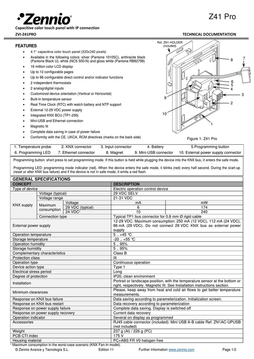
1. Place the metallic piece into a square or rounded standard mounting box with screws.
2. Connect the KNX bus, inputs and Ethernet at the rear of Z41 Pro, as well as the external power.
3. Once it is connected, fit Z41 Pro in the metal platform. The device is fixed through the magnets.
4. Slid Z41 Pro downwards to fix it with the security anchorage system. Check, from the side, that nothing unless Z41 Pro outline can be seen
(the metal platform should be completely hidden by Z41 Pro).
5. In case of landscape configuration, please follow the steps considering a 90º counter-clockwise rotation.
To uninstall proceed in the reverse way.
Any combination of the next accessories is allowed in the inputs:
Switch/Sensor
Push button
Up to two motion sensors
can be plugged into the
same device input (parallel
wiring)
Screw terminal for
connecting Zennio motion
sensors*
* In case of using ZN1IO-DETEC-P sensor, its micro switch number 2 must be in Type B position.
