manuals.online logo
Brands
  1. Home
  2. •
  3. Brands
  4. •
  5. Zeversolar
  6. •
  7. Inverter
  8. •
  9. Zeversolar Zeverlution 3680 User manual

Zeversolar Zeverlution 3680 User manual

I
n
1.
U
b
r
2.
H
3.
A
I
f
1.
L
Quic
k
Zever
l
532-
0
n
verte
r
W
1×
U
se a Φ10
m
r
acket to t
h
H
ang the in
v
A
ttach the
o
f
additiona
l
Figur
e
L
oosen the
Danger to li
f
Before perfo
reactivated.
k
Insta
l
l
ution 36
0
8111-0
1
W
all bracke
t
1×
m
m bit to d
r
h
e wall.
v
erter ont
o
o
uter fins
o
l
groundin
g
e
A
four scre
w
f
e due to hig
rming the ele
c
l
lation
80/400
0
1
Mounting
accessory ki
t
1×
r
ill 2 holes
o
the wall
b
o
f heat sin
k
g
or equipo
t
F
w
s of the c
o

h voltages i
n
c
trical conne
c
Guide
0
/5000
t
DC pl
u
conne
c
2
×
at a depth
b
racket sli
g
k
to both si
d
t
ential bon
d
F
igure B
o
ver using
a
n
the inverte
r
c
tion, ensure t
h
u
g
c
to
r
Seali
n
plu
g
2
×
of about 7
0
g
htly down
w
d
es of the
w
d
ing is req
u
a
TX25 scr
e
r
he DC switch
&
n
g
g
s
WiFi
a
(op
t
×
1
0
mm, inse
r
w
ards.
w
all brack
e
u
ired, grou
n
e
wdriver a
n
&
AC circuit b
r
a
ntenn
a
t
iona
l
)
c
o
1
×
r
t the wall
e
t using M
5
n
d the inve
r
nd remove
r
eaker are s
w
Smart mete
r
o
nnecto
r
(opti
o
1×
anchors a
n
5
screws, a
r
ter as sho
w
the cover.
w
itched off an
d
www.ze
v
r
o
na
l
)
Doc
u
n
d attach t
h
s shown in
w
n in Figu
r
d
cannot be
v
ersolar.c
u
mentatio
n
1
×
h
e wall
Figure A.
r
e B.
om
2
1. Zeve
r
the d
i
2. Zeve
r
all do
c
3. Zeve
r
4. Zeve
r
accor
d
modul
5. PV m
1.0μ
F
6. Whe
n
condu
c
can le
a
7. All c
o
8. Zeve
r
Zeve
r
The i
n
coun
t
Icon
- Mount
t
- Ensure
- Ambie
n
- Ensure
the inv
e
- The m
o
inverte
r
- If mou
n
a solid
s
recom
m
- Do not
- Mount
t
- Electri
c
- Obser
v
or obj
e
Reco
2. AC c
a
3. Inser
t
ferrul
e
the co
n
4. Thre
a
5. Inser
t
blade
6. Tight
e
7. Secu
r
1. DC c
a
2. Lead
Press
t
the s
w
torqu
e
Conne
c
3. For u
Inser
t
insert
t
sealin
g
DC inp
u
Danger
When e
compo
n
the DC
c
•Do not
•Do not
•Do not
•Do not
•Have t
h
•If an er
•Before
r
lution is a
t
i
rect curre
n
r
lution mu
s
c
umentatio
n
r
lution is s
u
r
lution mu
s
d
ance with
es to the i
n
odules wit
h
F
.
n
exposed t
o
c
tors and t
h
a
d to lethal
o
mponents
r
lution com
r
lution also
n
verter lab
e
t
ries and re
g
Ex
p
Ge
n
-
i
Ha
z
Ho
t
t
he inverte
good acce
n
t tempera
t
optimum
o
e
rter to dir
e
o
unting me
t
r
's weight
a
n
ted in a re
s
s
urface, pl
a
m
ended du
e
put any ob
t
he inverte
c
al connec
t
v
e the reco
m
e
cts as fol
l
Dire
c
mmended
a
ble requir
e
t
the cond
u
e
acc. to
D
n
tact.
a
d the AC c
t
the PE, N
a
: 1×5.5, tor
q
e
n the swi
v
r
e the cov
e
a
ble requir
e
the stripp
e
t
he clampi
n
w
ivel nut up
e
: 2.0Nm).
c
t the asse
nused DC
c
t
the sealin
t
he DC plu
g
g
plugs int
o
u
ts on the
i
to life due to
h
xposed to su
n
n
ents of the i
n
c
onnectors fr
o
disconnect t
h
touch non-in
s
touch the DC
touch any liv
e
h
e inverter m
o
ror occurs, h
a
connecting t
h
t
ransform
e
n
t from P
V
s
t only be
o
n
relating
t
u
itable for
i
s
t only be
o
IEC 61730,
n
verter.
h
a high ca
p
o
sunlight,
t
h
e live com
electric sh
o
must rem
a
plies with t
complies
w
e
ls with th
e
g
ions, plea
s
p
lanation
n
eral warn
i
mportant
s
z
ardous v
o
t
surfaces
r in areas
w
ss to the i
n
t
ure shoul
d
o
peration a
e
ct sunligh
t
t
hod, locat
a
nd dimen
s
s
idential a
r
a
sterboar
d
e
to audibl
e
jects on th
e
r verticall
y
t
ion area
m
m
mended
c
l
ows to en
s
c
tion
min. clear
a
e
ments as
f
u
ctor into
t
D
IN 46228
able throu
g
a
nd L cond
u
q
ue: 1.2Nm
)
v
el nut of t
h
e
r in the se
q
e
ments as
e
d cable all
n
g bracket
to the thr
e
mbled DC
p
c
onnectors
g plug into
g
connecto
o
the corre
s
i
nverter.

h
igh voltages
n
light, the PV
a
n
verter. Touc
h
o
m the invert
h
e DC connect
s
ulated cable
e
conductors.
e
component
s
o
unted, instal
l
a
ve it rectified
h
e PV array, e
n
e
rless pho
t
array into
o
perated b
y
t
o its instal
l
i
ndoor and
o
perated w
i
applicatio
n
p
acity to gr
o
t
he PV arr
a
ponents of
o
cks.
a
in within th
he EU Lo
w
-
w
ith the re
q
e
CE mark a
n
s
e visit we
b
ing
s
afety info
r
o
ltage
w
here it ca
n
n
verter for
d
be ≤40°
C
nd extend
s
t
, rain and
s
i
on and su
r
s
ions.
r
ea, we rec
o
d
and simil
a
e
vibration
s
e
inverter.
y
or tilted
b
m
ust point d
c
learances
s
ure suffici
a
nces
f
ollows:
t
he suitabl
e
and crim
p
g
h the cabl
u
ctors to t
h
)
. The assig
h
e cable gl
a
q
uence 1 to
the way in
down unti
l
e
ad and tig
h
p
lug conne
c
,
push dow
the DC plu
rs with
s
ponding
of the PV arr
a
a
rray genera
t
h
ing the DC co
e
r under load
ors under loa
e
nds.
s
of the invert
e
ed and com
m
by qualified p
n
sure that th
e
t
ovoltaic (
P
grid-comp
y
qualified
p
l
ation, co
m
outdoor u
s
i
th PV arra
y
n
class A.
D
o
und must
o
a
y generat
e
the invert
e
eir permitt
e
-
Voltage Di
q
uirement f
o
n
d RCM m
a
b
site (
ww
w
r
mation
n
not be to
u
installatio
n
C
to ensur
e
s
ervice lif
e
s
now.
r
face must
o
mmend
m
a
r material
s
s
when in u
s
Do not co
v
b
ackward b
y
ownwards
to walls,
o
ent heat di
s
above
300mm
e
p
e gland.
h
e screw te
r
nment is a
c
a
nd by usi
n
4 (screw
d
to the DC
l
it audibly
s
h
ten the c
o
c
tors to th
e
n the clam
g connect
o
Objec
t
A
B
C
D
The PE i
ay
t
es dangerou
s
nductors or t
h
, an electric a
r
d.
e
r.
m
issioned onl
y
ersons only.
e
DC switch is
P
V) inverte
r
liant alter
n
p
ersons wi
t
m
missionin
g
s
e.
y
s (PV mo
d
D
o not con
n
o
nly be us
e
e
s dangero
u
e
r. Touchin
g
e
d operati
n
rective 20
0
o
r safety a
n
a
r
k
. For mo
r
w
.zeverso
l
Icon
u
ched inad
v
n
and possi
e
optimal o
e
by avoidi
n
be suitabl
e
m
ounting t
h
s
are not
s
e.
v
er the inv
e
y
max. of 1
.
o
ther inver
t
s
sipation.
belo
w
500m
r
minal blo
c
c
cording to
n
g a torque
d
river type
:
plug conn
s
naps into
p
o
nnector (S
e
inverter.
ping brack
e
o
r. Tighten
Description
External dia
m
Conductor cr
o
Stripping len
g
Stripping len
g
nsulated con
d
s
DC voltage
w
h
e live comp
o
r
c may occur
y
by qualified
p
switched off
a
r
with two
n
ating curr
e
t
h the app
r
g
, operatin
g
d
ules and
c
n
ect any so
u
e
d if their c
o
u
s DC volta
g
g
the DC co
n
n
g ranges a
t
0
6/95/EC a
n
d EMC in
A
r
e informa
t
l
ar.com
).
v
ertently.
ble servic
e
peration.
n
g exposin
g
e
for the
h
e inverter
o
e
rter.
5°
t
ers,

w
si
d
m
20
0
c
ks and tigh
the label o
n
of 2.5Nm.
:
T25,torq
u
follow:
ector.
p
lace. Pus
h
W15,
e
t and pus
h
the DC plu
g
m
ete
r
o
ss
-
section
g
th of the ins
u
g
th of the out
e
d
uctor must
b
w
hich is prese
n
o
nents can le
a
leading to el
e
p
ersons with t
a
nd it cannot
b
MPP track
e
e
nt.
r
opriate ski
g
and main
t
c
abling) of
p
u
rces of e
n
o
upling cap
a
g
e which is
n
ductors o
r
t
all times.
nd the EM
C
A
ustralia a
n
t
ion about
c
Explan
Time n
energ
y
WEEE
d
Obser
v
e
.
g
o
n
d
es
0
mm
ten them (
s
n
the circui
t
u
e: 2.2Nm).
h
h
the swive
g
connecto
u
lated conduc
t
e
r sheath of t
h
b
e 5mm long
e
n
t in the DC c
o
a
d to lethal el
e
e
ctric shock a
n
he appropriat
b
e reactivate
d
e
rs which
c
lls who ha
v
t
enance.
p
rotection
n
ergy othe
r
a
city does
n
present in
t
r
the live c
o
C
Directive2
n
d New Zea
l
c
ertificates
ation
eed to dis
c
y
d
esignatio
n
v
e the doc
u
s
crew driv
e
t
board.
l nut up to
r (torque:
2
t
ors
h
e AC cabl
e
e
r than the L a
o
nductors an
d
e
ctric shocks.
n
d burns.
e skills.
d
.
c
onverts
v
e already
class II in
r
than PV
n
ot exceed
t
he DC
o
mponents
004/108/
E
l
and marke
in other
c
harge sto
r
n
u
mentation
e
r type:
the thread
2
.0Nm). Fi
n
Valu
e
9 mm to 14
4 mm² to 6
approx. 12
m
approx. 70
m
a
nd N conduct
o
d
the live
If you discon
n

read
E
C.
ts.
r
ed
.
n
ally
mm
mm
²
m
m
m
m
o
rs
n
ect
3
1
1. RS485 and Ethernet connection
Cable requirement :
- Comply with the standards for structured
cabling according to EIA/TIA-568.
- Shielding.
- CAT-5E or higher.
- UV-resistant for outdoor use.
- RS485 cable maximum length 1000m ,
- Network cable maximum length 100m .
1.1 Unscrew the swivel nut of the cable gland,
take out the seal insert and remove the filler-plug.
1.2 Thread the swivel nut over the cable, push the cable into the side slot in the seal insert,
thread the cable through the cable gland.
1.3 Plug the RJ45 connector into the RJ45 port in the inverter until it snaps into place.
1.4 Push the seal insert back into the cable gland. Tighten the swivel nut slightly.
1.5 Ethernet connection diagram.
Please make sure that the router's DHCP function is activated.
2 WiFi connection (optional).
2.1 Take off the sealing cap and tighten the antenna to the WiFi connection port.
2.2 WiFi Connection diagram.
Please make sure that the inverter is power-on before executing following steps.
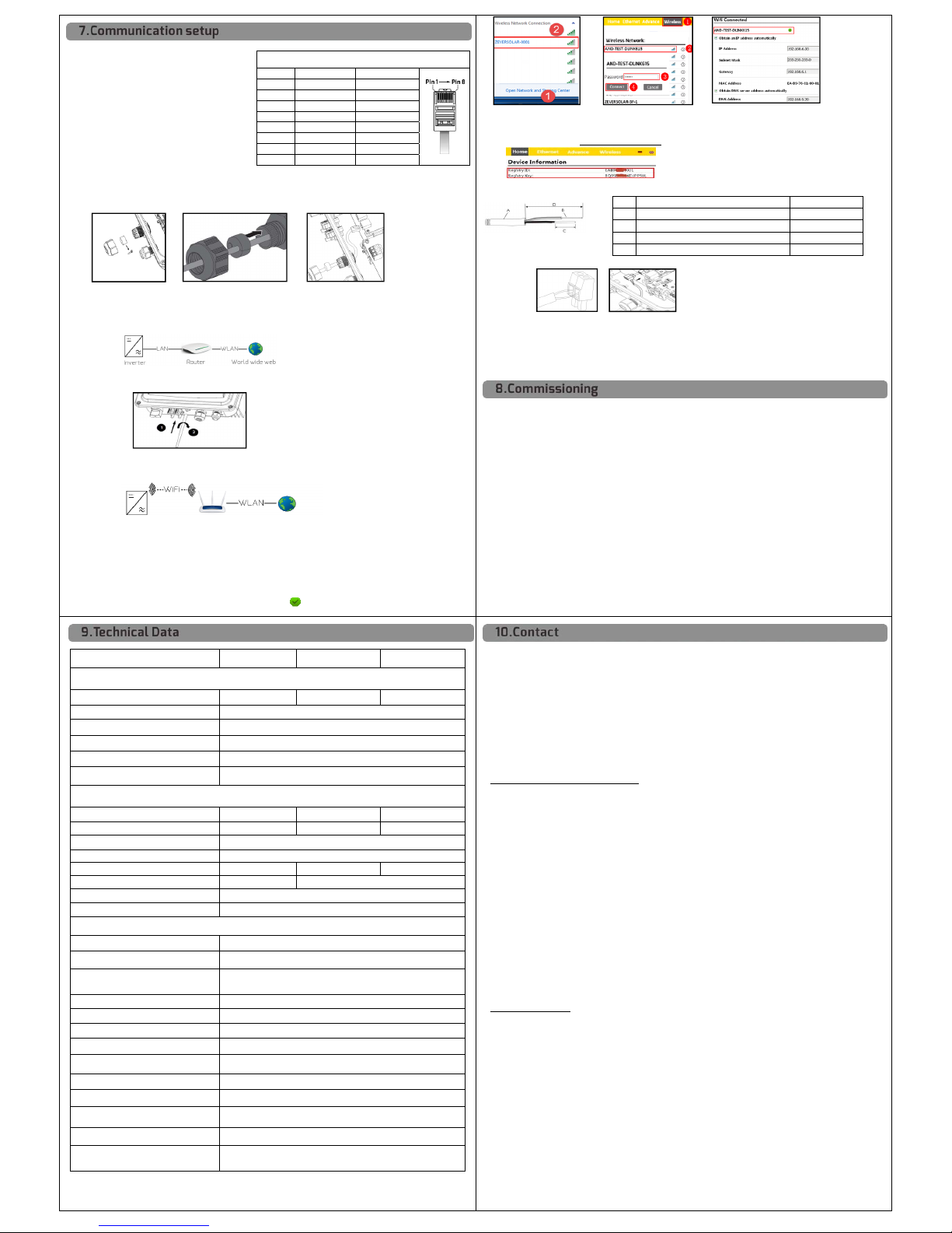
2.3 Open your mobile device or laptop’s WLAN page. The new access point called ZEVERSOLAR -XXXX is
displayed. Note: "XXXX" stands for the last four digits in the Registry ID (Figure C).
2.4 Connect to the access point using your mobile device or laptop, the password is ‘zeversolar’.
2.5 Start the web browser and type in" http://160.190.0.1." The internal website will open.
2.6 Select a router in the [Wireless] area. The Password/Security Key dialog box will pop up.
Enter the password of the router (Figure D). If the WiFi device is connected to the router successfully,
the status indicator on the wireless page will display the icon (Figure E).
Pinout assignment for RJ45 wiring
Pin No. Pin definition
Color
Pin1 TX_RS485
A
white
-
g
reen
Pin2 TX_RS485B
g
reen
Pin3 RX_RS485
A
white
-
oran
g
e
Pin
4
GND
blue
Pin5 GND
W
hite
-
blue
Pin6 RX_RS485B
oran
g
e
Pin7 +7V
white
-
brown
Pin8 +7V
brown

FigureC FigureD FigureE
2.7 Note the Registry ID and Key, they will be used for creating new plant in ZeverCloud,
please visit website (www.zevercolud.com) .
3 Smart meter connection(optional)
3.1 Cable requirements:
3.2 Route the cable into inverter through the cable gland, cable connection referring to section 7.1.
 FigureG
3.3 Connect the conductors to the supplied smart meter connector in accordance with the symbol.
When doing so, ensure the conductors are plugged completely into the terminal up to the insulation.
3.4 Plug the assembled smart meter connector into the pin connector (Figure G),
3.5 Push the seal insert back into the cable gland. Tighten the swivel nut slightly.
3.6 Place the cover on the housing, then tighten all 4 screws with a Torx screwdriver (TX25) .
Check
-Check that the inverter’s exposed metal surface has a ground connection.
-Check that the DC voltage of the strings does not exceed 600V.
-Make sure that the DC voltage has the correct polarity.
-Make sure that the resistance between PV arrays and ground is greater than 1Mohm.
-Make sure that the AC circuit breaker must be correctly rated and mounted.
-Check that the grid voltage at the point of connection of the inverter is within the permitted range.
-Make sure that the inverter and wall bracket have been correctly mounted.
-Make sure that the cover has been correctly mounted.
-Make sure that cables are routed in safe place or protected against mechanical damage.
-Make sure that unused DC inputs on the inverter have inserted by DC plug connectors with sealing plugs.
-Make sure that the communication and AC cable glands have been correctly mounted and tightened.
Commissioning
After finishing the above checks, switch on the DC switch, then check various settings in the display and
make changes if necessary. Ensure the correct safety setting has been selected for the region, then switch
on the AC circuit breaker. When there is sufficient DC voltage applied and the grid connection conditions
are met, the inverter will start operating automatically.
Objec
t
Description
Valu
e
A
External diamete
r
5 mm to 8 mm
B
Conductor cross
-
section
0.14 mm² to 1.5 mm
²
C
Stripping length of the insulated conductors
approx. 9 mm
D
Stripping length of the outer sheath of the cabl
e
approx. 30 mm
Zeverlution 3680 Zeverlution 4000 Zeverlution 5000
DC Input
DC convertible power(@cosφ=1) 3900W 4650W 5300W
Max. DC input voltage 600V
Min. DC start voltage 80V
Max. DC input current 11A/11A
Number of independent MPP inputs 2
Strings per MPP input 1
AC Output
Rated active power 3680W 4000W 5000W
Max. apparent AC power 3680VA 4400VA 5000VA
Rated power frequency 50/60Hz
R
ated grid voltage 220/230V
Max. AC output current 16
A
20
A
23
A
Line circuit breaker B25 B32
Adjustable displacement power factor 0.8Ind ...1…0.8cap
Harmonic distortion (THD) at rated output < 3%
General data
PV ISO / Grid monitoring ●/●
GFCI function ●
Communication interfaces: RS485 /
Ethernet / WIFI ●/ ○/ ○
Earth Fault Alarm cloud based, audible and visible (AU)
Dimensions (W x H x D) 341x 395 x172 mm
Weight 11kg
Noise emission < 25 dB(A)@1m
DC connection SUNCLIX DC connector
AC connection Screw terminal block
Operating temperature range -25℃…+60℃
Relative humidity (non-condensing) 0% … 100%
Max. operating altitude 4000m(>3000m derating)
Degree of protection
(according to IEC 60529) IP65
●standard ○optional
If you have any technical problems concerning our products, please contact Zeversolar service.
We require the following information in order to provide you with the necessary assistance:
- Inverter device type
- Inverter serial number
- Type and number of connected PV modules
- Error code
- Mounting location
- Warranty card
Zeversolar Factory Warranty
Warranty card will be shipped with inverter. You can download the current warranty conditions at
www.zeversolar.com/service/warranty.
Regional service are available by contacting the following numbers during working hours:
Australia
Phone: +61 13 00 10 18 83
E-Mail: [email protected]m
Great China
Phone: +86 512 69 37 09 98-8866
E-Mail: service.china@zeversolar.com
European Region
Phone: +49 221 48 48 52 70
E-Mail: [email protected]
Rest of the world
E-Mail: service.row@zeversolar.com
For more information, please download the user manual and other technical documents at
www.zeversolar.com.

Fi
g
ure F
7
4
6
5

Other manuals for Zeverlution 3680

3

This manual suits for next models

2

Other Zeversolar Inverter manuals

Zeversolar Zeverlution 3680 User manual

Zeversolar

Zeversolar Zeverlution 3680 User manual

Zeversolar Zeverlution Series Manual

Zeversolar

Zeversolar Zeverlution Series Manual

Zeversolar Evershine TLC4000 User manual

Zeversolar

Zeversolar Evershine TLC4000 User manual

Zeversolar Evershine TLC5000 User manual

Zeversolar

Zeversolar Evershine TLC5000 User manual

Zeversolar Zeverlution 3680 User manual

Zeversolar

Zeversolar Zeverlution 3680 User manual

Zeversolar Zeverlution Pro 33K. User manual

Zeversolar

Zeversolar Zeverlution Pro 33K. User manual

Zeversolar Eversol TL1000-20 User manual

Zeversolar

Zeversolar Eversol TL1000-20 User manual

Zeversolar Zeverlution S User manual

Zeversolar

Zeversolar Zeverlution S User manual

Zeversolar Eversol-TLC 10K User manual

Zeversolar

Zeversolar Eversol-TLC 10K User manual

Zeversolar Evershine TLC4000 User manual

Zeversolar

Zeversolar Evershine TLC4000 User manual

Zeversolar Evershine TLC User manual

Zeversolar

Zeversolar Evershine TLC User manual

Zeversolar Zeverlution 1000S User manual

Zeversolar

Zeversolar Zeverlution 1000S User manual

Zeversolar Zeverlution 1500S User manual

Zeversolar

Zeversolar Zeverlution 1500S User manual

Zeversolar Eversol-TLC 10K User manual

Zeversolar

Zeversolar Eversol-TLC 10K User manual

Zeversolar Zeverlution 1000S User manual

Zeversolar

Zeversolar Zeverlution 1000S User manual

Zeversolar Zeverlution 1000S Assembly instructions

Zeversolar

Zeversolar Zeverlution 1000S Assembly instructions

Zeversolar Zeverlution 3680 User manual

Zeversolar

Zeversolar Zeverlution 3680 User manual

Popular Inverter manuals by other brands

PowMr SOLXPOW X2 Series user manual

PowMr

PowMr SOLXPOW X2 Series user manual

GE HOME NERATOR 10000 WATT Operator's manual

GE

GE HOME NERATOR 10000 WATT Operator's manual

OUKITEL PV400W user manual

OUKITEL

OUKITEL PV400W user manual

SolaX Power X3-Hybrid-5.0-D user manual

SolaX Power

SolaX Power X3-Hybrid-5.0-D user manual

ZEPIA EnergyApS SW-150 instruction manual

ZEPIA EnergyApS

ZEPIA EnergyApS SW-150 instruction manual

SMA SUNNY TRIPOWER 8.0 operating manual

SMA

SMA SUNNY TRIPOWER 8.0 operating manual

AOTAI MIG350MC operating manual

AOTAI

AOTAI MIG350MC operating manual

Voltec 10-00474 owner's manual

Voltec

Voltec 10-00474 owner's manual

SHENZHEN ENCOM ELECTRIC TECHNOLOGIES CO. EN500 Series Service manual

SHENZHEN ENCOM ELECTRIC TECHNOLOGIES CO.

SHENZHEN ENCOM ELECTRIC TECHNOLOGIES CO. EN500 Series Service manual

PowerTech MI-5085 user guide

PowerTech

PowerTech MI-5085 user guide

Bergey POWERSYNC II Series Operator's manual & installation instructions

Bergey

Bergey POWERSYNC II Series Operator's manual & installation instructions

EG4 8KEXP-240V user manual

EG4

EG4 8KEXP-240V user manual

Mitsubishi Electric FR-A8NCE instruction manual

Mitsubishi Electric

Mitsubishi Electric FR-A8NCE instruction manual

Epcom EPIG5K user manual

Epcom

Epcom EPIG5K user manual

Well Well Triumph 230V 500VA 300W instruction manual

Well

Well Well Triumph 230V 500VA 300W instruction manual

SolaX Power Solax Box 3.0 Quick installation guide

SolaX Power

SolaX Power Solax Box 3.0 Quick installation guide

DENAFRIPS TERRA MCLK owner's manual

DENAFRIPS

DENAFRIPS TERRA MCLK owner's manual

KUSSMAUL 450-0700-0 instruction manual

KUSSMAUL

KUSSMAUL 450-0700-0 instruction manual

manuals.online logo
manuals.online logoBrands
  • About & Mission
  • Contact us
  • Privacy Policy
  • Terms and Conditions

Copyright 2025 Manuals.Online. All Rights Reserved.