ZIMO MS450 User manual

INSTRUCTION MANUAL
MS450, -R, MS450P22, -P16
MS440C, MS440D
MS480, -R, -F, MS480P16
MS490, -R, -F, MS490N, -L
MS500, -R, -F, MS500N
MS560
MS580N18, MS580N18G
MS590N18
MS950 and LOKPL950
MS990L, MS990K and LOKPL990
MN330, -R, MN330P22
MN340C, MN340D
MN300, -R, -F, MN300P16
MN170, -R, -F, MN170N
MN180N18
MS–SOUND DECODERS
for SW version 4.229
including a pre-description of the features of version 5.00
Small decoders shown enlarged (1.5:1)
Large scale decoder in original size
EDITIONS:
First version for first delivery, SW version 1.00 --- 2018 04 17
2018 07 20
2018 08 23
SW version 2.00 --- 2019 01 08
2019 01 25
SW version 2.04 with lookout to later versions --- 2019 02 20
2019 05 30
2019 08 08
SW version 4 with lookout to later versions --- 2019 09 11
2019 11 22
2019 12 09
Miniature and NEXT types added, revisions --- 2020 03 05
SW version 4.10 with lookout to 5 --- german ed.
Large scale types added, updates --- 2020 06 29
SW version 4.50 --- german ed.
SW version 4.75 --- german ed.
german ed.
2021 05 12
SW version 4.90 --- 2021 05 21
SW version 4.95 --- 2021 06 15
2021 06 29
SW version 4.215 --- 2022 05 05
2022 05 27
2022 08 01
SW version 4.225 --- 2022 11 10
2022 12 05
2022 12 15
2023 02 01
2023 05 02
MN Types and Sound Equalizing added --- 2023 07 11
& MN –Non-Sound Decoder

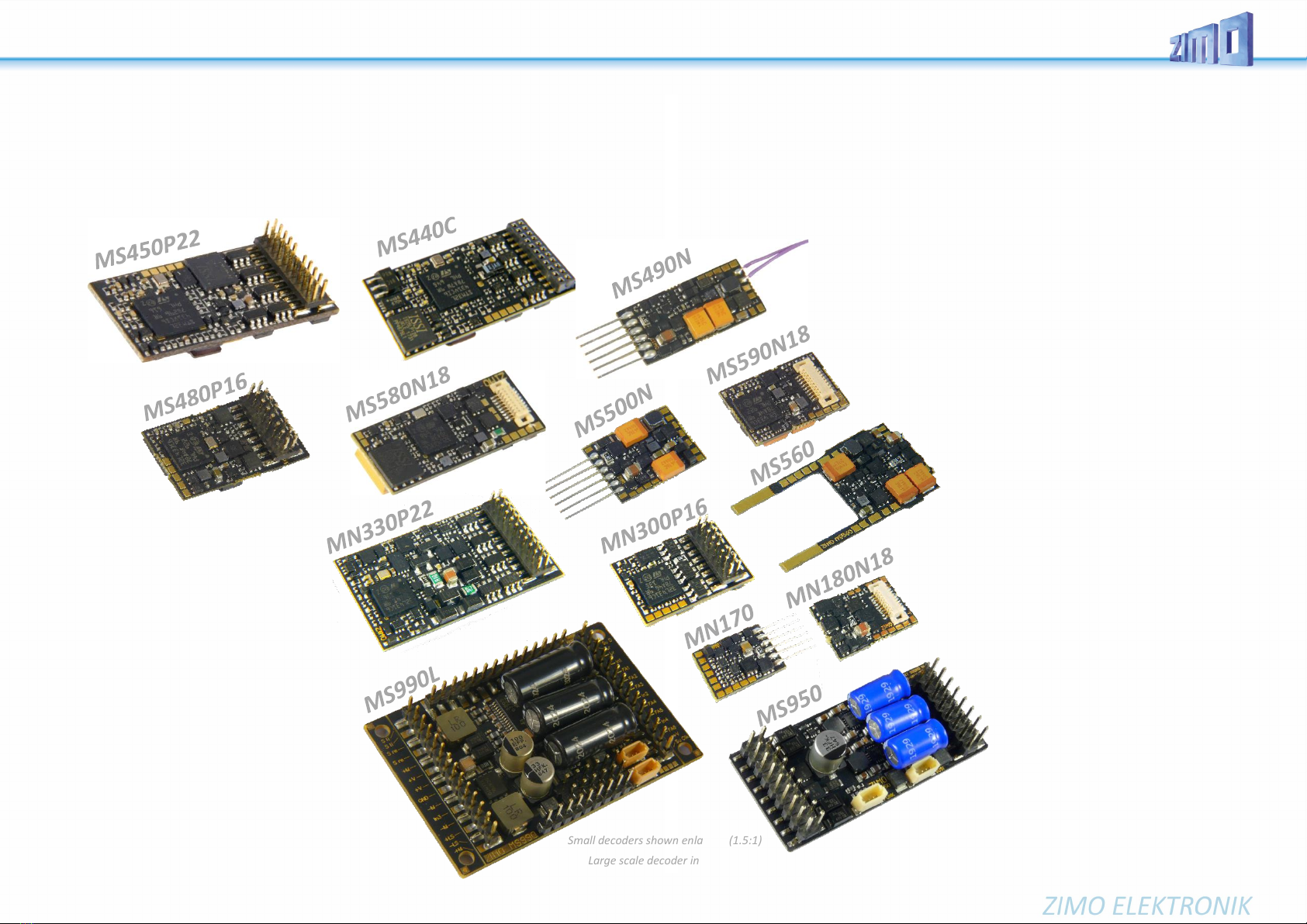
Page 2 MS - SOUND decoders MS440 to MS990 and MN - NON-SOUND decoders MN170 to MN340
Contents
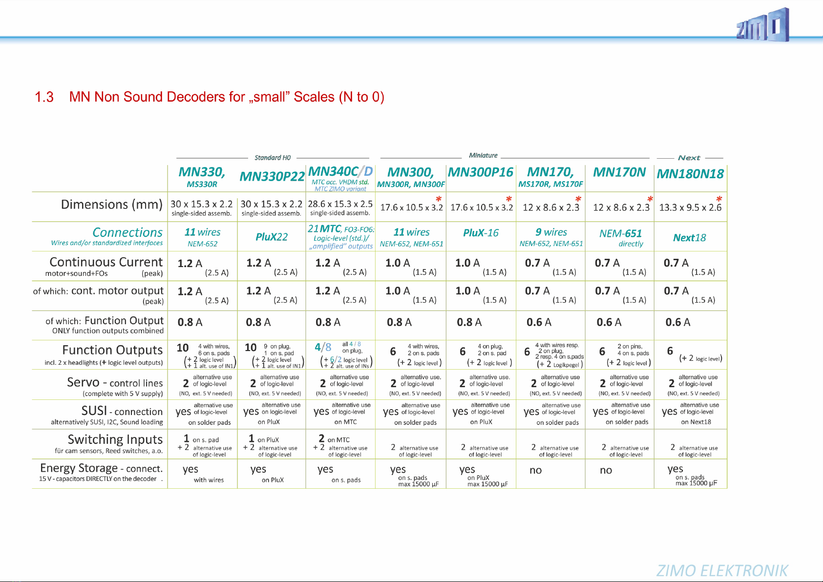
1Overview of the types and type-dependent data.................................................................. 4
2Technical Data, schematics, operation with mfx.................................................................. 7
3
2B
CVs in DCC operation....................................................................................................... 22
4
3B
RailCom - “Bidirectional communication” for DCC ............................................................. 44
5
4B
ZIMO SOUND –Selection and Programming.................................................................... 46
6Sound equalizing (filter) of the MS sound decoders........................................................... 60
7Installation and connection of the ZIMO decoder............................................................... 62
8CV - Overview; CVs in numerical order............................................................................. 64
9Scripts for decoders, short description............................................................................... 82
10 Software update and sound loading with MXULFA............................................................ 83
11 Service Notes.................................................................................................................... 86
“mfx” is a registered trademark of Fa. Gebr. Märklin & Cie GmbH.
“RailCom” is a registered trademark of Lenz GmbH.
CHANGE PROTOCOL of this instruction manual
2019 09 11: Cover: MS440C
Page 3 - various changes
Page 34 - additional sound classes
Page 37 and following - added Diesel, Electro, random, …
Page 34 and following - various changes and additional entries to the CV tables
2019 12 09: Page 5 –MS950 added in decoder table; corrections (dimensions MS480, MS490, MS580, stay-alive capacitor cir-
cuitry), naming of MS580
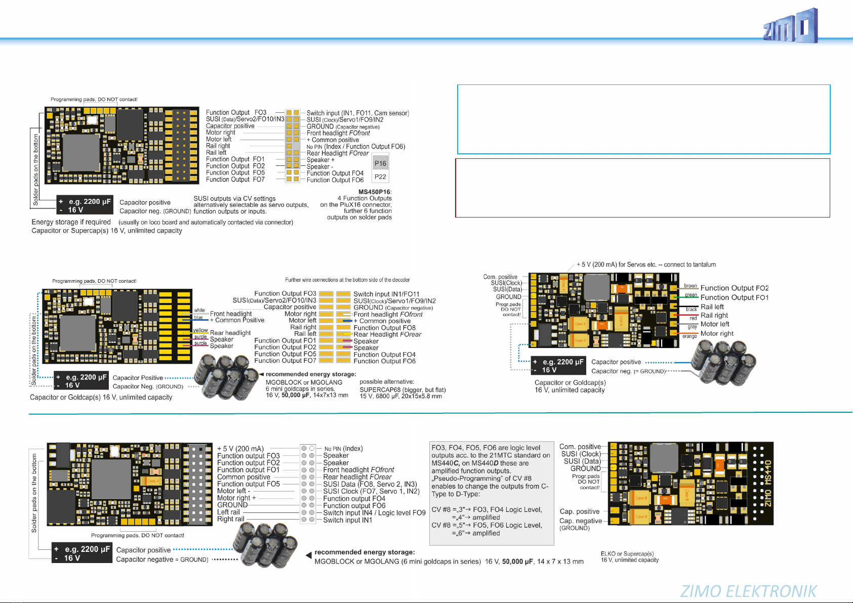
Page 7 - Connection schematics for MS440C/D
Page 25 - Changes to CV #190/191
2020 01 23: MS480, MS490, MS580 schematics added, MS450, MX450 schematics modified
2020 02 07 Page 35: Correction driving sound, table of volume settings
2020 03 25 Drawings and text stay-alive capacitor of MS580
2020 06 29 Corrections accordingly and summarising the German-language editions
Connection diagrams and types overview updated
2021 02 03 Corrections accordingly and summarising the German-language editions
2021 04 23 Addition of "StayAlive" to connection diagrams, various CV #153,…
Additions to the type table, separation into "small" types and large scale decoders
2021 04 29 Addition of cover images
2021 05 12 Improvements of the schematics, new pages for MS990L, -K
2021 05 21 Chapter 7: Software Update and Sound Load with MXULFA
Chapter 3.26: New CV #264 low voltage for large scale and special decoders
Chapter 3.25: Addition for servo control lines 5-8
Chapter 5: CV additions according to the above points
2021 06 14 NEW: Chapter 3.12 "Distance-controlled stopping - constant braking distance".
Chapter 3.11: New, reference to CV #29, Chapter 3.1: Description for CV #27 new
2021 06 29 Chapter 3.24 modified, Alternative application of SUSI pins; Various corrections
2022 05 05 Cover: MS560
2022 08 01 MS480, MS490, MS500, MS590: Rev. B. Details of stabilised low-voltage sources added to diagrams and tables. Chapter 2: Warning
for PIKO boards
2022 11 10 Chapter 6: Installation notes for older locomotives
several CVs changed or added (CV #10, #195-#199, #134, ...),
Chapter numbers in CV list (chapter 8) are now clickable
2022 12 05 Correction of the connection diagrams of MS950 and MX605FL (see MS560)
2022 12 15 various corrections and additions (CV #203 / #204, missing links,…)
2023 02 01 added CV #250 for MN decoders, CV #27 –Bit 2 removed, Added Information for CV #49, #50. #56
2023 04 27 several small corrections
2023 07 11 Addition of MN Decoders, new Chapter Sound euqalizing, several small changes and updates
2023 07 11
SUMMARY of features not yet implemented in SW version 4.229 (preview to 5.00)
oMotor brake (for non-worm gear): CV #151 (only if not in consist, otherwise it is used differently)
oAdaptive acceleration and special possibilities for acceleration: CVs #123, #394, #246, #348 *
oChange between individual and consist address via key, CV #197; reduction control, CV #151
oSpecial operating state “km/h regulation”: CVs #135, #136 *)
oThe “CV #300 procedure” and test drive for basic load: CVs #300 - #302
oSound classes rolling sounds, second thyristor, panto sounds: CVs #588, #593, #594, #596, #598
oSpecial measures (interruption Acceleration) for diesel-mechanical locomotives: #364, #365
oLarge scale decoder: 2nd smoke generator; with 4.205 already cylinder drainage and start 2nd diesel engine
o"Stereo" (large scale decoder, 2 sound output channels, settings in CV page 31/32 = 145/0);
oTilt and curvature sensor launch for display on controller and sound influence.
oControl influence CV #58, load dependence steam/diesel: CVs #277-#279, #280, #154, #158, #378-#379
------------------------------------
*) the marked block of features will be updated in regards to the MX generation, because, on the one hand the
performance will be enhanced, and on the other hand, it will present advances for future operation types (first
planned new feature in this regard: display of target distance on the controller).

MS - SOUND decoders MS440 to MS990 and MN - NON-SOUND decoders MN170 to MN340 Page 3
Notes for users switching from MX to MS & MN:
The relationship between MS - Sound Decoders &
MN - non-sound decoders
In contrast to earlier decoder generations (at ZIMO and other manufacturers),
the sound decoders - i.e. the more elaborate types - were the first on the market
at MS & MN. The types without sound are largely derived from this: so they are
NOT trimmed for low cost, but for optimal functionality as it results from the
match:
MS sound decoders and MN non-sound decoders are of one mold.
Identical hardware, apart from the special components for sound generation, of
course, and jointly developed software mean
- same driving behavior (important for locomotive networks, etc.),
- same (very similar) configuration, including ZIMO specials like
"Swiss Mapping", scripts, registration under DCC and mfx, etc.
- same project organization (sound projects or decoder projects)
Therefore, there is this one shared operating manual for sound and non-
sound decoders. Sections that refer only to sound can of course be ignored
for non-sound.
Differences concerning operation and config. (MX
→
MS & MN):
Apart from the new sound quality (see below) and other improvements, the MS and
MN decoders are very similar to the MX decoders. In some cases, though, specific
settings (CVs) behave differently or have additional functions for better operation:
CV #12 (Operation types): according to VHDM-standard, individual operating states
can be locked (DCC, mfx, MM, analog), by default all unlocked. Chap. 3.1
CVs #5, #57 (top speed, Reg’ref.): CV #5 gets the original configuration to reduce
the top speed back, which was in CV #57 in MX decoders. CV #57, therefore,
is used to select, whether the speed depends on running voltage or if voltage
variations can be eliminated by references to a lower value (e.g. 14 V). NOT
in SW. 4.50! Chapter 3.6
CV #56 (P- and I-value): only effective, if CVs #147, #148, #149 = 0 Chapter 3.6
CV #144 (Programm./Update lock): dropped, no longer necessary in new decoders.
CV #147, #148, #149 (PID settings): new CVs, enable separated, high-resolution
adjustment of integral, differential, and proportional values for EMF-load bal-
ance control, replace CV #56 if <> 0. Chapter 3.6
CVs #190, #191 (Brightening up and dimming times for effects 88, 89, 90): New def
inition due to broader range of timeset (now 0-320s). Chapter 3.21
CVs #49, #50 In contrast to MX decoders the values of CV #3/#49 or #4/#50 are not
added together, but the higher value is used. Chapter 3.7

Page 4 MS - SOUND decoders MS440 to MS990 and MN - NON-SOUND decoders MN170 to MN340
1 Overview of the types and type-dependent data
Technical data for all MS sound decoders in the next chapter!
*)To make the small dimensions possible, the decoder families MS490, MS500 and MS590N18 are NOT mfx-able!
**) Valid for MS480 and MS490 decoders (all types in each case) from revision B (produced from approx. August 2022 onwards).

MS - SOUND decoders MS440 to MS990 and MN - NON-SOUND decoders MN170 to MN340 Page 5

Page 6 MS - SOUND decoders MS440 to MS990 and MN - NON-SOUND decoders MN170 to MN340
NOTE: There are NO MN Non-Sound Decoders for large scale!
*)Decoder MN170, MN180 und MN300 (jeweils alle Typen) sind NICHT mfx-fähig; dadurch sind die kleinen Abmessungen möglich.

MS - SOUND decoders MS440 to MS990 and MN - NON-SOUND decoders MN170 to MN340 Page 7
2 Technical Data, schematics, operation with mfx
Technical data for all MS sound decoders:
Allowable track voltage H0 and large scale decoders.................................................. 7 V - 35 V
Miniature- and Next-Decoders ............................................... 7 V - 24 V
Decoder together with StayAlive controller STACO1/STACO2/STACO3 12.5 V - 18 V
(Miniature decoders can withstand a track voltage higher than 30 V only for a short time (< 1 sec) –e.g.
for Märklin-switching impulse)
Operating temperature ............................................................................................... - 20 to 80 °C
Sound sample memory ........................................................ 128 Mbit (= 360 sec at 16 bit / 22kHz
up to 1440 sec with 8 bit / 11 kHz) *)
Resolution of the sound samples and the play back quality ............................................ 8 or 16 bit
Sample rate of the sound samples and the playback .............................................. 11, 22, 44 kHz
Number of independent sound channels .................................................................................... 16
*) those playback times are all “theoretical”; in praxis, 5 % to 20 % of the memory are not available, because
they are reserved for organization, descriptions, GUI-info, sounds to load later, etc.
This calculation is based on a maximum sample rate of 22 kHz, because 44 kHz does not provide real im-
provement to quality.
Data on the STACO1, STACO2 and STACO3 StayAlive controller
(in conjunction with miniature decoder)
Rail voltage for charging the Goldcaps...................................................................... 12.5 V - 18 V
Max. permitted rail voltage.......................................................................................................18 V
Constant output voltage..............................................................................................approx. 10 V
Charging current:
STACO1: ................................................................................................................max. 45 mA
STACO2 and STACO3 ........................................................................................... max. 25 mA
Time to charge from 0 to 100 %:
STACO1, STACO2A and STACO3A..................................................................................31.2 s
STACO2B and STACO3B...................................................................................................104 s
Discharge current example.................................................................................................. 75 mA
Discharge time at discharge current example:
STACO1 with 2 resp. 3 Goldcaps ........................................................................ 1.58 s resp. 3 s
STACO2A and STACO3A...................................................................................................1.22 s
STACO2B and STACO3B...................................................................................................3.12 s
Technical data for all MS sound decoders:
See previous chapter “Overview of the types and type-dependent data”
The decoder type can be read out in CV #250 if needed:
1 = MS500 3= MS490 5 = MS580 7 = MS990 9= MS950
2= MS480 4 = MS440 6 = MS450 8 = MS590 10 = MS560
123 = MN340124 = MN170125 = MN300 126 = MN330 127 = MN180
Software Update:
You need a device that can perform updates: ZIMO MXULF/A (decoder updating and sound loading
device), ZIMO central command station MX10, or Roco digital central Z21. The new SW version is
downloaded from www.zimo.at, loaded into a flash drive or sent to the updating device via USB-con-
nection to a computer and ZSP to an updating device, which then executes the actual update via the
track input of the decoder.
This is (generally) also the way a sound project is loaded into a ZIMO decoder.
In general, both UPGRADE (the "normal" process, update to newer version) and DOWNGRADE (ex-
ceptional cases, update to older version) are possible; BUT: Downgrade of decoders with SW version
from 4.200 to SW versions older than 4.200 is NOT possible.
See chapter "10 Software update and sound loading with MXULFA" in this operating manual and
MXULF(A) operating manual; especially downgrade limit for SW version 4.200!
Overload and thermal protection:
The motor and function outputs of ZIMO decoders are designed with lots of reserve capacities and are
additionally protected against excessive current draw and short circuits. Cut-outs are encountered if
the decoder is overloaded.
Even though the decoder is well protected; it is not indestructible. Please pay attention to the following:
Wrong decoder contact: if, for example, the motor leads have contact to track power or an overload connection
between the motor brushes and rail pick-ups, this is not always recognized by the overload protection circuit and
could lead to damage of the motor power amplifier or even a destruction of the decoder.
Unfit or defective motors: e.g. coil or commutator shorts are not always recognized by their high current consump-
tion, because these are often just short current spikes. So, they can lead to decoder damage including damage to
power amplifiers due to long-term exposure.
The power amplifiers of loco decoders (motor as well as function outputs) are not only at risk of overcurrent but also
voltage spikes, which are generated by motors and other inductive consumers. Depending on track voltage, such
spikes can reach several hundred volts and are absorbed by special protection circuits inside the decoder. This is
why the running voltage shall not be too high, i.e. not higher than intended by the corresponding vehicle.
ZIMO decoders are equipped with temperature sensors to measure their own operating temperature. Power to the
motor will be turned off once that temperature exceeds 100°C. The headlights start flashing rapidly, at about 5 Hz, to
make this state visible to the operator. Motor control will resume automatically after a drop in temperature of about
20°C (i.e. to about 80°C), typically in about 30 seconds.

Page 8 MS - SOUND decoders MS440 to MS990 and MN - NON-SOUND decoders MN170 to MN340
MS450P22, MS450P16 Top side (with PluX22, -16)
MS450, MS450R, MS450F Top side with wires
MS440C, MS440D Top side, with 21MTC, SOUND
NOTE: External capacitors on MS440, MS450
Capacitors (Elkos, Supercaps) of any capacity can be connected to “Capacitor positive” (to
ROUND) WITHOUT additional components; they do NOT have to be able to handle full running volt-
age; 16 V is enough. Prerequisites for the connection for the stay-alive capacitor within the decoder
prevent an inrush current too high and enable undisturbed Service Monde programming, software
updates, sound loading, also with higher capacities and use the memory the best possible way.
MS450 all types Bottom side (example with wires)
MS440C, D Bottom side, with 21MTC, SOUND
Servo control lines on SUSI pins (applies to all decoders except large-scale)"
Servo control lines on the SUSI pins are activated by CVs #181, #182). These connections work with
a voltage level of 3.3 V (difference to MX decoders where 5 V).
Some servos do NOT work with 3.3 V! Possible remedy: lower the supply voltage (normal 5 V)
to about 4 V; otherwise, only replacement will help; digital servos are better!

MS - SOUND decoders MS440 to MS990 and MN - NON-SOUND decoders MN170 to MN340 Page 9
MN330P22 Top side, with PluX22, NON-SOUND
MN330, MN330R Top side with wires, NON-SOUND
MN340C, MN340D Top side, with 21MTC, NON-SOUND
MN330 all types bottom side (e.g. with wires), NON-SOUND
MN340C, MN340D Bottom side, NON-SOUND

Page 10 MS - SOUND decoders MS440 to MS990 and MN - NON-SOUND decoders MN170 to MN340
MS480, MS480R, MS480F Top side with wires
MS480P16 Top side (with PluX16)
Bottom side MS480, MS480P16 (drawing shows wired version)
MN300, MN300R, MN300F Top Side with wires, NON-SOUND
MN300P16 Top side with PluX16, NON-SOUND
Rev. B only! (Produced from August 2022)
Rev. B only!
(produced from
August 2022)

MS - SOUND decoders MS440 to MS990 and MN - NON-SOUND decoders MN170 to MN340 Page 11
ATTENTION:
In vehicles equipped with a 6-pin NEM 651 interface (where a decoder like MS490N or MS500N is plugged
in),"functions" (lights, ...) are NOT connected to the decoder plus pole (because there is no pin), but hang on
the "artificial plus pole" (2 diodes) of the loco board. Thus, an external energy storage (e.g. STACO1 and Gold-
caps) does NOT affect the lights (they flicker when the track is dirty ...), but "only" on motor and sound. At the
same time such an "artificial plus pole" hinders the functional safety of ABC.
POSSIBLE REMEDY:
The positive poles of theconsumers would have to be disconnected from the"artificial plus pole" and connected
to the "common plus pole" of the decoder by wire.
MS490, MS490R, MS490F Top side wired
MS490N, MS490L NEM 651
Energy storage solution with STACO1 on the MS490…
MN170, MN170R, MN170F Top side, wired . NON-SOUND
MN170N Top side, with NEM 651 . NON-SOUND
… resp. with ELKO or Tantalum on the MS490, …R, …F, …N
Bottom side
Rev. B
produced
from August
2022
Rev. A

Page 12 MS - SOUND decoders MS440 to MS990 and MN - NON-SOUND decoders MN170 to MN340
MS500, MS500R, MS500F Top side with wires
MS500N NEM651
Energy storage solution with STACO1 or ELKO on the MS500
External capacitors directly on
miniature decoders MS480, MS490, MS500
Elkos with 1000 µF can be connected to "ELKO Plus" WITHOUT additional
components according to the circuit diagrams on this page. They do NOT have to
be able to handle full running voltage; 15 V is enough. However, the capacity must
not exceed 1000 µF, which only provides little protection against motor juddering
and sound disturbances.
Bigger capacitors can be connected instead or additionally (practically without
limitation) to “common positive” and GROUND, although, WITH additional compo-
nents and a dielectric strength suitable for the running voltage (usually 25 V):
The resistor prevents an inrush current too high, the diodes enable Service mode
programming, software updates and sound loading by dropping the voltagein spite
of higher capacities.
External capacitors on miniature decoders over
- controller
STACO1/STACO3
STACO1 10 x 7.3 x 2 mm STACO1 (centre) connected to miniature sound decoder
(CAD enlarged) MS490N and 3 miniature Goldcaps in series (scale 1:1)
The StayAlive controller is connected via wires to the solder pads
“common positive” and "GROUND" of the decoder (two-pole!).
The STACO1 comes with 3 mini Goldcaps (STACO3: 2 mini Goldcaps) as the ac-
tual energy storage, which, connected in series, represent a capacity of 100,000 µF
(STACO3A: 150,000µF, STACO3B: 500,000 µF). Of course, all 3should preferably
be connected, but it also works with 2 (with about 50 % runtime) if there is a lack of
space. The STACO1/STACO3 board contains a step-up voltage converter that
sucks the Goldcaps from their fully charged state (8 V if 3 of them; 5.2 V if 2) to
their almost fully discharged state (2 V) and delivers a constant voltage of 10 V.
This is enough to drive and to supply the soundamplifier (which runs on 5 V) without
interruption and without loss of volume.
To avoid overheating, decoders with STACO1 or STACO3 connected may only be
operated with a maximum rail voltage of 18 V. The wire connections between the
controller board and the mini Goldcaps make their local separation possible, and
thus in many cases the accommodation of the StayAlive technology.
NO bridge for three Goldcaps!

MS - SOUND decoders MS440 to MS990 and MN - NON-SOUND decoders MN170 to MN340 Page 13
MS580N18 Top side (with Next18)
NOTE: External energy storage with MS580N18
The “Next decoder” MS580N18 contains a bigger internal capacity with
a voltage of 5 V. The Tantal capacitors provide the sound amplifier and the
motor (only with 5 V, which is enough for slow driving) in case the track voltage
is interrupted. The internal capacity is enough for a stay-alive of about 0.1 sec
and thereby preventscracking noises and gets throughshort powerless sections.
This internal capacity can be expanded externally, either by
•further Tantals of the same type (to be connected via a small wire bridge) or
by Elkos. The total capacity is NOT limited, a dielectric strength of the capaci-
tors of 6.3 V is enough, or
•two miniature Goldcaps connected in series (best possibility, if there is
enough room, but it can also be put at any other place within the loco con-
nected via wires). Types with 12 x 4 mm (length x diameter) are available as
MGOGURT with 2 x 0.3 F at 2.7 V, which enable a stay-alive of 1-2 seconds.
Goldcaps or Super caps with higher energy density are to be expected in fu-
ture.
If (for example because of the lighting) the buffer of the 5 V voltage is not
enough, but the full runningvoltage shall be buffered, capacitors (practically with-
out limitation) can be connected like to every other decoder, to “Gem. Pluspol”
(common positive), although, WITH additional components and a dielectric
strength suitable for the running voltage (at least 25 V), additionally to the tantals
described above or Goldcaps or alone:
Bottom side (with optional external extension of the stay-alive capacitor)
Stay alive time 1 - 2 sec!
Bottom side of type MS580N18G
(WITHOUT Tantals on the decoder, but wires to the external stay-alive capacitor).
Two connected Goldcaps are delivered with the package, they should be
soldered to the open ends of the wires. OBSERVE THE POLARITY (+/-)!

Page 14 MS - SOUND decoders MS440 to MS990 and MN - NON-SOUND decoders MN170 to MN340
MS590N18 Top side (with Next18), SOUND
NO connections on bottom side, therefore not shown here
MN180N18 Oberseite, mit Next18 . NICHT-SOUND
NO connections on bottom side, therefore not shown here
NOTE: External energy storage with MS590N18
Due to the extreme miniaturization, the “Next decoder” MS590N18 does NOT contain previsions
to connect an external energy storage directly.
It is possible to connect ELCOs (practically without limitation) to “GEM. Pluspol” (common posi-
tive) and ground, although, WITHadditional components and a dielectric strengthsuitable for the
running voltage (usually 25 V):
The resistor prevents an inrush current too high, the diodes enable Service mode programming,
software updates and sound loading by dropping the voltage despite higher capacities.
External capacitors on miniature decoders over - Controller
STACO1/STACO3 STACO2
2 mini Goldcaps, STACO3 and Next-Decoder (example MS590N18) in series
The StayAlive controller is connected via wires to the solder pads
“common positive” and "GROUND" of the decoder (two-pole!).
STACO3A: 2 mini Goldcaps à 0.3 F/2.7 V, 4 x 12 mm, 150,000 µF;
STACO3B: 2 mini Goldcaps à 1 F/2.7 V, 6.4 x 9.8 mm, 500,000 µF
The STACO1 comes with 3 mini Goldcaps à 0.3 F/2.7 V, 4 x 12 mm as the
actual energy storage, which, connected in series, represent a capacity of
100,000 µF.
Of course, all 3 should preferably be connected, but it also works with 2 (with
about 50 % runtime) if there is a lack of space.
The wire connections between the
controller board and the mini Gold-
caps make their positional separation
possible, and thus in many cases the
accommodationof the StayAlive tech-
nology.
The STACO boards contain a step-up
voltage converterthat sucks the Gold-
caps from their full charge state (8 V
for 3 pcs; 5.2 V for 2) to their almost
full discharge (2 V) and delivers a
constant 10 V voltage. This is enough
for driving and for uninterrupted sup-
ply of the sound amplifier (runs on
5 V) without volume loss.
StayAlive-Controller with
Next18-connection
A Next18 decoder can be
plugged on like on an adapter
board, the STACO2 then outputs
the decoder connections via 13
soldered strands.
The STACO2A set contains
13 soldered wires and
2x mini Goldcaps
à 0.3 F/2.7 V, 4 x 12 mm
The STACO2Bset contains
13 soldered wires and
2 mini Goldcaps à 1 F/2.7 V,
6.4 x 9.8 mm

MS - SOUND decoders MS440 to MS990 and MN - NON-SOUND decoders MN170 to MN340 Page 15
MS560 Top Side (when plugged into KATO vehicle)
NOTE: External energy storage to MS560
The MS560 "KATO decoder" does NOT include provisions for direct connection
of external energy storage devices.
ELCOs can be connected (practically without limitation) between “Gem. Pluspol”
(Common positive pole) and MASSE (GROUND), but WITH additional compo-
nents and a dielectric strength suitable for the driving voltage (usually 25 V):
The resistor prevents too high inrush current; the diodes enable service mode
programming as well as software update and sound charging despite larger ca-
pacities due to the voltage drop.
In addition to the actual (main) decoder - in this case the MS560 sound decoder - the equipment of
KATO vehicles (mostly multiple unit express trains such as ICE-4 or Shinkansen) includes special
function decoders for the headlights and interior lighting.
Such are available from the ZIMO MX decoder series:
External energy storage to “KATO-Decoder” MS560 via
- Controller STACO1
STACO1 10 x 7.3 x 2 mm
(CAD 2:1 vergrößert) STACO1 (Mitte), „KATO-Decoder“ MS560
und 3 mini Goldcaps in Serie geschaltet (Maßstab 1:1)
The StayAlive controller is connected to the terminals (solder pads orwires) "Common positive"
and "GROUND" of the decoder (two-pole!).
The STACO1 comes with 3 mini Goldcaps as the actual energy storage, which are connected
in series and represent a capacity of 100,000 µF. Of course, preferably all 3 should be con-
nected, but it also works with 2 (with about 50 % runtime) if there is a lack of space. The
STACO1 board contains a step-up voltage converter, which sucks the Goldcaps from their full
charge (8 V, if 3; 5.2 V, if 2) to their almost full discharge (2 V) and delivers a constant voltage
of 10 V. This is enough for driving and for an uninterrupted supply of the sound amplifier (which
runs on 5 V) without loss of volume.
Instead of a STACO1, a STACO3 can be used.
MASSE
Pluspol
vom/zum
Decoder
MASSE
Plus
von/zu
2 oder 3
Goldcaps

Page 16 MS - SOUND decoders MS440 to MS990 and MN - NON-SOUND decoders MN170 to MN340
MS950 (Rev.B)
LOKPL950 loco board, suitable for large scale decoder MS950
(shown in smaller scale)
MS950 Bottom side (with base plate)
Base plate above the back of the MS950, visible: ELCO Plus and GROUND connector

MS - SOUND decoders MS440 to MS990 and MN - NON-SOUND decoders MN170 to MN340 Page 17
Schematic MS955
- Content follows -

Page 18 MS - SOUND decoders MS440 to MS990 and MN - NON-SOUND decoders MN170 to MN340
MS990L Top Side
The loco board for
the large scale
decoder MS990L
(shown in smaller scale)
MS990 is produced and shipped in the fol-
lowing basic variations:
as MS990L
with 3 x 14-pole pin connector (see figure left),
the outmost pins on the left and the right pin con-
nectors were mainly added for a 2 x 14 pin Märklin
interface; the connectors are otherwise used rarely
(due to the doubled pins or a second SUSI inter-
face).
as MS990K
with 2 x 12 and 1 x 12 pole screw terminals
(as mentioned above, the outmost connections on
the left and on the right side are not needed).
Special editions
(Mixture of pin connectors and screw terminals, or
editions with less outputs)
can be produced on demand.

MS - SOUND decoders MS440 to MS990 and MN - NON-SOUND decoders MN170 to MN340 Page 19
Schematic MS990K
NOTE:
External energy storage on MS990
Generally, the internal capacitor (3 Goldcaps and
a step-up transformer to produce full running volt-
age from the 3 x 3 V Goldcaps) is sufficient for al-
most all applications.
Nevertheless, there is a possibility to connect an
additional capacitor between “ELKO Plus” (capac-
itor positive) and ground: External capacitor need
a dielectric strength of up to 16 V, the capacity is
unlimited - we recommend the ZIMO products
GOLMRUND and GOLMLANG, for example.
Connecting “normal Elkos/capacitors” would be
unnecessary (although the connection is named
“ELKO”), because they do not provide a significant
contribution compared to the internal stay-alive ca-
pacitor.
The base
of the large-scale
decoder MS990
(shown in smaller scale)

Page 20 MS - SOUND decoders MS440 to MS990 and MN - NON-SOUND decoders MN170 to MN340
Mfx operation with the Märklin Central Station 3
The pictures below are screenshots of the Märklin Digital Central CS3 (via the corresponding web
browser) and show the registration process of a ZIMO MS sound decoder. The decoder type does not
matter in this case; of course, it has to be mfx-able (i.e. NOT MS490, MS590).
The MS decoder in this example has loaded the sound project of the European Steam/Diesel Collec-
tion), which is typical for ZIMO shipment and reproduces sounds of BR50, BR70, BR 03.10 (Steam
locos) or a BR 211 (Diesel).
The “sound collection” (i.e. more than one loco in a project) is a ZIMO specialty and therefore not
especially supported by Märklin command stations; the usage, although - including the selection of a
loco type - is still possible, using a trick. This is also described in the pictures.
In case of a “normal” sound project (for a single loco), the usage of the MS decoder is even easier: The
part starting with “Selecting a loco type” is not needed.
In this example: first there was no loco on the tracks.
... and is followed by reading out decoder data.
The registration was successful; loco name (in case of a sound col-
lection: name of the first loco type, i.e. “BR 50”) is displayed. How-
ever, no picture is displayed. Instead “???”. NOTE see above!
After enlarging the window with the controller bar, speedo and function
symbols are displayed (the symbols were selected when registering from
the decoder). The loco can be driven with the regulator knob.
NOTE concerning the allocation of a loco picture (valid in 2020, perhaps also in 2021):
Currently and for the time being, i.e. until the implementation of another registration procedure within the
Central Station, which is confirmed by Märklin and will consider loco pictures
for non-Märklin decoders, there are the following possibilities:
- After successful registration (if “???” is shown instead of a picture), you can select a picture from the
collection of pictures within the Central Station (see CS instruction manual).
- Sometimes, a picture is automatically selected (by matching the name).
- If you want to use your own picture, you can load it into the Central Station and can then select it from
one of the existing pictures within the collection (see CS instruction manual, chapter
“Importing Locomotive Images Using the Web Browser”.
By activating the red loco symbol, the registered loco is taken
over by the controller.
The decoder (lco) is positioned on the tracks, registration begins...
Other manuals for MS450
1
This manual suits for next models
41
Table of contents
Other ZIMO Media Converter manuals
Popular Media Converter manuals by other brands

Microsens
Microsens 10/100Base-TX to 100Base-FX user manual

KTI Networks
KTI Networks KSC-361 user manual

Avermedia
Avermedia ExtremeCap SDI BU111 quick guide

Moxa Technologies
Moxa Technologies IMC-P101 Series Hardware installation guide

SC&T
SC&T Data Transmission Series user manual

Ultravolt
Ultravolt 60W manual