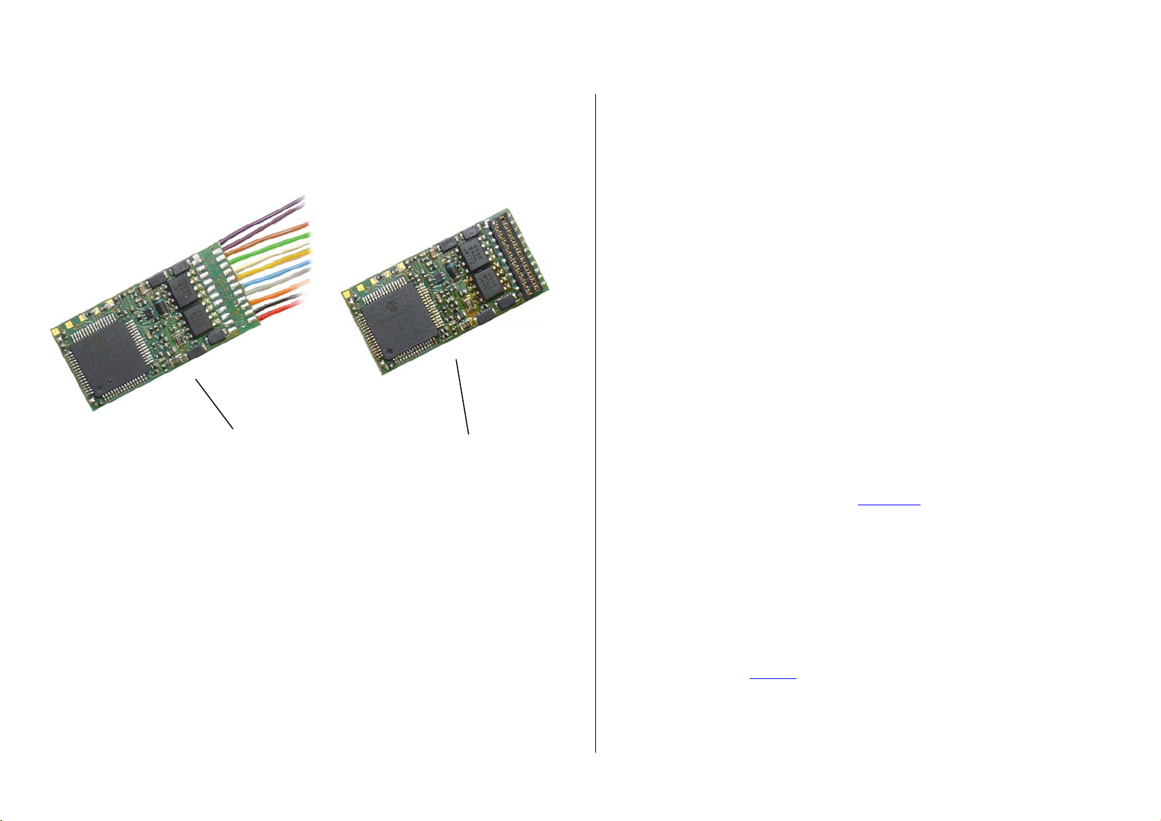
Page 6 H0 Sound Decoder MX640
THE MX640 CONFIGURATION VARIABLES:
Configuration Variables can be defined within the programming procedures to improve the driving
characteristics of a locomotive and for many other application specific adjustments.
The meaning of Configuration Variables (CV’s) is in part standardized by the NMRA DCC REC-
OMMENDED PRACTICES, RP-9.2.2. There are however certain CV’s that are for Zimo decoders
only, in some cases exclusively for specific types of Zimo decoders.
Always use the specifications for the decoder in question, since the value range may differ between
manufacturers, even with standardized CV’s; in this case use the table below.
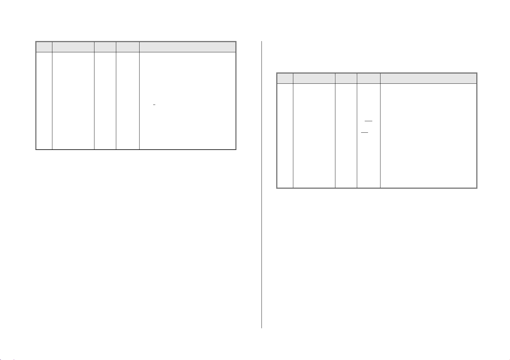
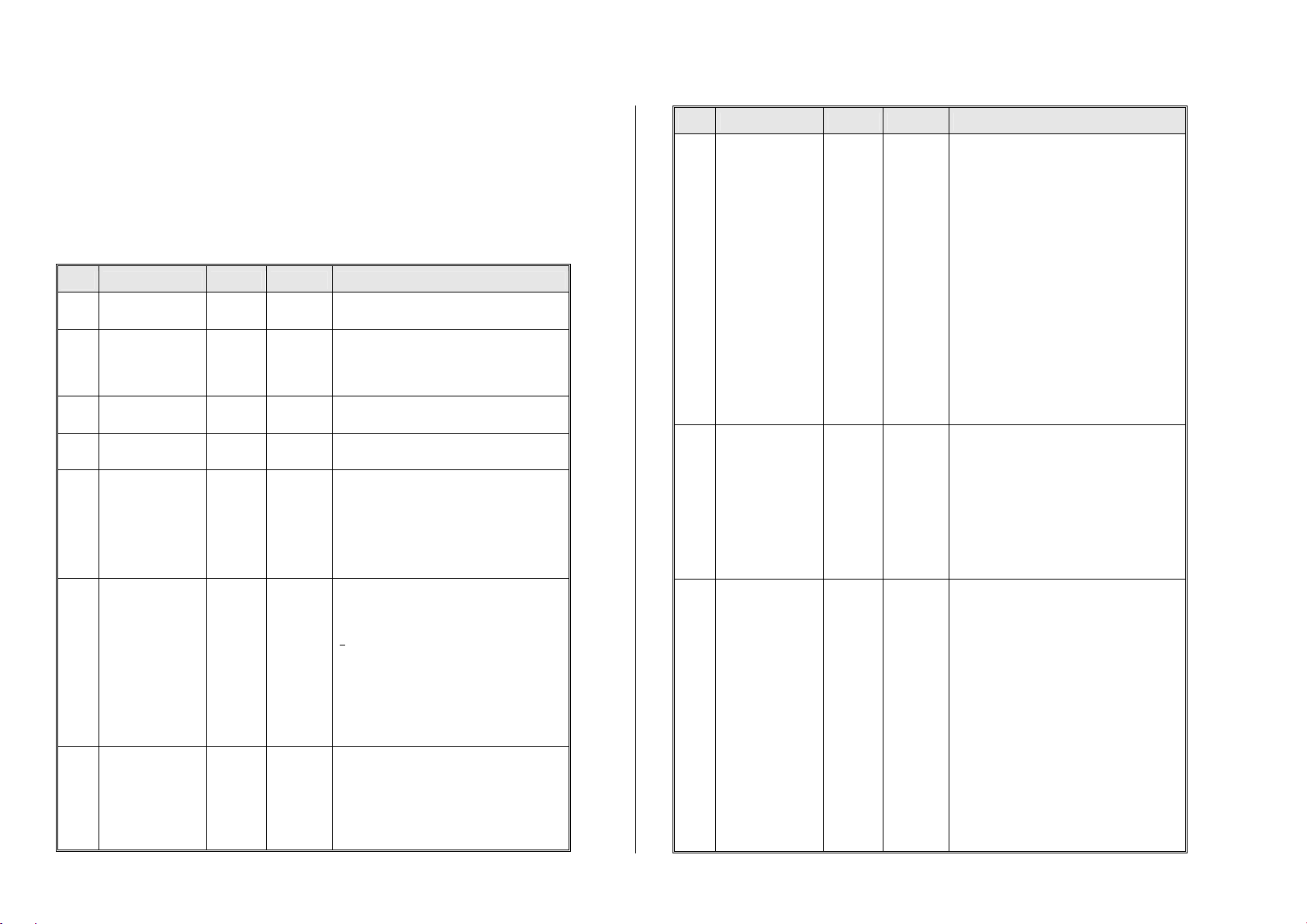
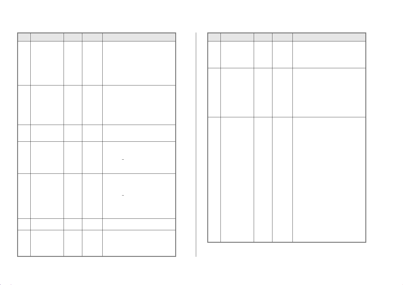
CV Designation Range Default Description
#1 Loco
address 1 – 127 3 The “short” (1-byte) loco addresses; Is active
when Bit 5 in CV #29 is 0.
#2 Vstart
1 – 252
(See add.
notes) 2
Entered value = internal speed step assigned
to lowest cab speed step.
Bit 4 in CV # 29 has to be 0; otherwise individ-
ual speed table is active.
#3 Acceleration rate 0 - 255 12 Multiplied by 0.9 equals’ acceleration time in
seconds from stop to full speed.
#4 Deceleration rate 0 - 255 12 Multiplied by 0.9 equals’ deceleration time in
seconds from full speed to complete stop.
#5 Vhigh
0 – 252
(See
add. notes) 1 (= 252)
Entered value = internal speed step assigned
to highest cab speed step, according to the
number of speed steps selected (14, 28 or
128).
0 and 1 = no effect.
Bit 4 in CV #29 has to be 0, otherwise speed
table is active.
#6 Vmid
1,
A useful
value for is
¼ to ½
of the
value in
CV #5
(See
add. notes)
1
( = about 1/3 of
top speed)
Entered value = internal speed step assigned to
the cabs center speed step (=step 7,14 or 63 ac-
cording to the number of speed steps selected: 14,
28 or128)
“1" = default (medium speed is 1/3 of full speed,
that is: with CV #5 = 255, CV #6 is 85, otherwise
lower).
Bit 4 in CV #29 has to be 0, otherwise speed table
is active.
The 3-point curve that results from the settings
in CV’s #2, 5, 6 is automatically smoothed out;
not jolt noticed at mid-speed!
#7
Software version
and
Temporary register when
programming with a “Lok-
maus 2” and similar low
level systems.
Read only
Only version
number can
be read
Pseudo-
Programming
This CV normally displays the decoder soft-
ware version.
For user of Lokmaus 2 :
Pseudo-programming (because programmed
value is not really stored) as an initial step for
programming or read-out of a higher CV (#>99)
and/or a higher value (>99) for systems that
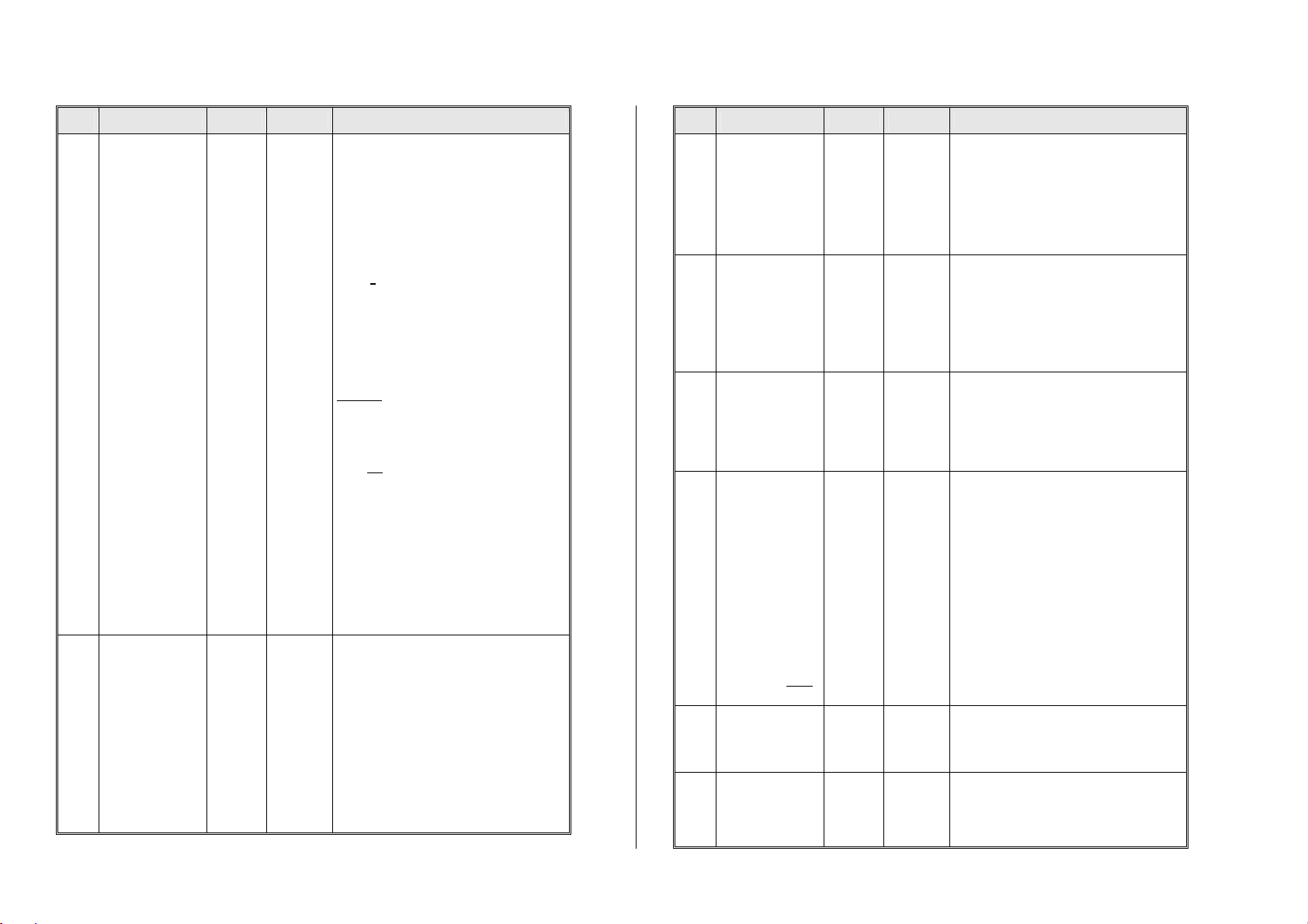
CV Designation Range Default Description
See section “Operation
within other systems” in this
manual.
And for
programming help of higher
CV numbers with „medium
level“ systems such as
Intellibox or Lenz; especially
for sound sample selection
and sound CV’s.
I.e. to program
CV #300 = 100
with values:
for
Lokmaus 2:
1, 2,
10, 11, 12,
20, 21, 22
And for
Sound-Prog:
110, 120,
130,
210, 220,
230
(see chap-
ter 6)
can only program a limited within a limited
number and value range :
Ones digit = 1: The entered CV value will be
increased by 100 during the actual program-
ming.
Ones digit = 2: …increases by 200.
Tens digit = 1: The entered CV number will be
increased by 100 during the actual program-
ming.
Tens digit = 2: ….increases by 200.
Tens digit = 3: ….increases by 300.
Hundredth digit = 1: CV number conversion is
retained until system is powered down.
= 2: ...is retained until reset
with CV #7 = 0.
For Lokmouse-2: see section „ZIMO decod-
ers in competitor systems“!
SOUND – selection and programming:
see chapter 6!
#8
Manufacturer ID
and
HARD RESET
with CV #8 = 8
or
LOADING
of special CV sets
Read only
all additional
programming
is pseudo
only; read-out
always shows
“145”, which is
ZIMO’s
assigned
number
145
( = ZIMO)
NMRA assigned manufacturer ID for Zimo is:
145 (”10010001”)
Pseudo-Programming (”Pseudo” = pro-
grammed value is not really stored):
CV #8 = “8” -> HARD RESET (NMRA standard:
all CV’s reset to default values).
CV #8 = “0” -> HARD RESET (ZIMO special: all
CV’s reset to currently stored sound project).
CV #8 = “9” -> HARD RESET for LGB-operation
(14 speed steps, pulse chain).
#9
Motor frequency
and
EMF
sampling rate
Recommendation
for coreless mo-
tors, i.e.
MAXXON,
FAUL-HABER:
CV #9 = 22 or 21
0
High
frequency,
mid-range
sampling
rate
1- 99
High
frequency,
modified
sampling
rate
or
255-176
Low
frequency
(See add.
0
High
frequency,
mid-range
sampling
rate
=0: Default motor control with high frequency
(20 / 40 kHz) and an EMF-sampling rate that
automatically adjusts between 200Hz (low
speed) and 50Hz.
Tens digit 1 - 4: Reduced sampling rate com-
pared to default (less noise!)
Tens digit 6 - 9: Increased sampling rate com-
pared to default (one of the steps against buck-
ing!)
Ones digit 1 – 4: EMF sampling time shorter
than default setting (good for coreless motors
for less noise, more power)
Ones digit 5 - 9: EMF sampling time longer
than default (may be needed for 3-pole motors
or similar)
= 255 - 176: Low frequency - PWM according
to formula (131+ mantissa*4) *2exp. Bit 0-4 is
“mantissa”; Bit 5-7 is “exp”. Motor frequency is
the reciprocal of the PWM.