Page 4 Large-scale Decoder & Sound Decoder MX695/6/7/9
2 Technical Information
.
Track Voltage in digital mode (DCC) ................................................................................. 10 - 30 V
(peak) in analog mode (High voltage pulse for direction reversal) ........................................ 35 V
Threshold voltages in analog mode - see below!
Maximum continuous motor output = maximum continuous total output MX695.......................... 6 A
Maximum continuous motor output = maximum continuous total output MX696, MX697............. 4 A
Maximum continuous motor output = maximum continuous total output MX699.......................... 6 A
Maximum peak current (Motor only or total) ............................................................................. 10 A
Number of function outputs …..MX695KV, MX695LV, MX695KN, MX696V ….……………...........14
MX699KV, MX699LV ...................................................................15
MX695KS, MX695LS, MX696S, MX696N, MX699KS, MX699LS .8
MX697V, MX697S .......................................................................10
Maximum continuous function output current ........................................................................... 2 A
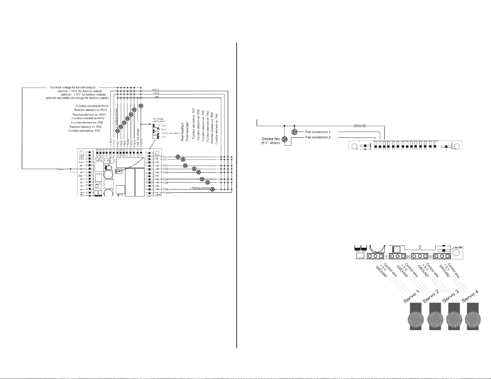
Maximum continuous output for low-voltage functions (5 V, 10 V, adjustable) ................. each 1 A
Voltage range for adjustable low-voltage functions (MX695KV, -LV) .............................. 1.5 to 16 V
Maximum current at special output for Smoke-Ventilator (5 V - Motor) with brake function . 200 mA
Storage capacity for sound samples .................................................................................. 32 Mbit
Playback frequencies according to sound sample …...................................................... 11 or 22 kHz
Number of simultaneously playable sound channels ..................................................................... 6
Sound-amplifier output at 4 Ohm ................................................................................. Sinus 10 W
Loudspeaker impedance........................................................ 8 Ohm, 2 x 8 Ohm parallel or 4 Ohm
Externally connectable energy storage device . .............................................charging voltage 17 V
for standard electrolytic capacitors ...................... >= 20 V, any capacity
Gold-caps (pack with 7 pieces at 2,5 V ea. - in series) >= 17 V, max. 1 F
Rechargeable battery (only with special circuitry) .............. 14.4 V pack
Charge current for external energy storage ......................................................................... 80 mA
Analog mode (DC or AC) *) ............................................Threshold-voltage headlights........... @ 4 V
Threshold-voltage sound................. @ 5 V
Threshold-voltage motor ..................@ 6 V
Operating temperature............................................................................................... - 20 to 100 oC
Dimensions (L x W x H including screw terminals) **) MX695-, -99KV, -KS ..... 50 x 40 x 13 mm
(L x W x H including pins)............................MX695-, -99LV ............. 50 x 40 x 13 mm
in cases of long plug-in pins for ESU-loco boards with MX695LS ...................... 50 x 40 x 20 mm
MX696 ......................... 55 x 29 x 16 mm
MX697 ......................... 56 x 32 x 21 mm
*) Actual analog-characteristics depend heavily on the type of power pack and the locomotive’s drive
train (because the transformer output voltage may collapse more or less under load)
**) Length given without break-away mounting brackets; these increase the length by 2 x 6 mm
RailCom is a registered trademark by Lenz Elektronik GmbH
ZIMO
ELEKTRON
IK
Schönbrunner
Straße
188,
1
120
W
ien,
Österreich
www.zimo.at offic[email protected] Tel +43 (1) 81 31 007 0
The decoder type can be read out in CV #250
130=MX630 (Rev. 2019) 135=MX635 136=MX636 137=MX637 142=MDS442
160=MX660 182=MX682 (2019) 190=MX659 192=MX622 (Rev. 2019) 193=MX638
195=MX616 196=KISS Silberlinge 197=MX617 198=FLM_E69 199=MX600
200=MX82 201=MX620 202=MX62 203=MX63 204=MX64
205=MX64H 206=MX64D 207=MX680 208=MX690 209=MX69
210=MX640 211=MX630-P2520 212=MX632 213=MX631 214=MX642
215=MX643 216=MX647 217=MX646 218=MX630-P25K22 219=MX631-P25K22
220=MX632-P25K22 221=MX645 222=MX644 223=MX621 224=MX695-RevB
225=MX648 226=MX685 227=MX695-RevC 228=MX681 229=MX695N
230=MX696 231=MX696N 232=MX686 233=MX622 234=MX623
235=MX687 236=MX621-FLM 237=MX633 238=MX820 RevA 240=MX634
241=MX686B 242=MX820RevB 243=MX618 244=Roco NextG 245=MX697
246=MX658 247=MX688 248=MX821 249=MX648-RevC,D 250=MX699
251=Roco 2067 252=Roco ICE 253=MX649 254=MX697-RevB
OVERLOAD PROTECTION
The motor and function outputs of the ZIMO large-scale decoders are designed with large re-
serve capacities and are additionally protected against over-currents and short circuits. Automat-
ic shutoff will occur in case of overload followed by automatic reboot attempts (which often re-
sults in flashing lights).
These safety precautions do not mean that the decoder is indestructible. Please pay attention to the
following:
Faulty decoder hook-up (mixed up connection wires) and improper electric connections between the motor
terminal and chassis are not always recognized and can lead to output driver damage or even total destruction
of the receiver.
Unsuitable or defective motors (e.g. with short-circuited turns or collectors) are not always recognizable by
their high consumption of electricity (only peaks may register) and can lead to decoder damage, sometimes
long term effects can cause output driver defects.
The decoders output drivers (for the motor and function outputs) are not only at risk through over-current but
also through voltage spikes as they are delivered from the motor and other inductive consumers. Depend-
ing on track voltage, such spikes can reach several hundred volts and are absorbed by special protection cir-
cuits inside the decoder. The capacity and speed of such elements is limited and so unnecessarily high track
voltage should not be used. Never use a higher voltage than recommended for a particular vehicle. Only in ex-
ceptional cases should the ZIMO adjustable range (up to 24 V) be utilized.
THERMAL PROTECTION
All ZIMO decoders come equipped with a sensor that detects the actual temperature. Once the
maximum permissible value (ca. 100 oC on the circuit board) has been reached, power to the
motor will be shut off. Rapidly flashing headlights (at ca. 10 Hz) will signal that a shut-off has oc-
curred. Motor operation will resume automatically after a drop in temperature of about 20 oC, typ-
ically after 30 to 60 sec.
SOFTWARE UPDATE
ZIMCO decodes are designed so that software updates can be completed by the user. This re-
quires a device with an update function (ZIMO decoder update module MXDECUP, or MXULF,
or “central system cab“ MX31ZL/MX32ZL, or command station MX10).The update itself is car-
ried out via a USB stick (MXULF, MX31ZL, MX32ZL, MX10) or via a computer with the “ZIMO
Sound Programmer” ZSP software or “ZIMO Rail Center” ZIRC software.
There is no need to remove the decoder; the locomotive does not need to be opened; it can be
placed onto the update-track (connected to the update-device) without any changes and can
then be updated via a USB stick or a computer.
Note: Locomotive accessories that are directly connected to a track (not controlled by the decoder) may inter-
fere with the update; in that case the locomotive will have to be opened and removed from the track.