ZIMO MX638 Series User manual

Non-Sound Decoder MX600 - MX638 and Sound Decoder MX640 - MX659 Page 1
INSTRUCTION MANUAL
THIN DECODER
MX600, MX600R, MX600P12
SUBMINIATURE –and MINIATURE DECODER NEXT 18 - DECODER
MX616, MX616N, MX616R MX618N18
MX617, MX617N, MX617R, MX617F
MX621, MX621N, MX621R, MX621F
MX620, MX620N, MX620R, MX620F,MX622, MX622R, MX622F, MX622N
HO –and TT DECODER
MX623, MX623R, MX623F, MX623P12
MX630, MX630R, MX630F, MX630P16
HO, (O) - DECODER for MORE POWER or LOW VOLTAGE output or MORE FUNCTIONS
MX631, MX631R, MX631F, MX631D, MX631C
MX632, MX632R, MX632D, MX632C, MX632V, MX632W, MX632VD, MX632WD
MX633, MX633R, MX633F, MX633P22, MX637P22
MX634, MX634R, MX634F, MX634D, MX634C, MX638D, MX638C
MINIATURE - SOUND - DECODER NEXT 18 –Sound - Decoder
MX648, MX648R, MX648F, MX648P16 MX658N18, MX659N18
MX647, MX647N, MX647L, MX646, MX646R, MX646F, MX646N, MX646L
MX649, MX649R, MX649F, MX649N, MX649L
HO, (O) - SOUND - DECODER
MX640, MX640R, MX640F, MX640D, MX640C,
MX642, MX642R, MX642F, MX642D, MX642C, MX643P16, MX643P22,
MX645, MX645R, MX645F, MX645P16, MX645P22, MX644D, MX644C
and: ADAPTER BOARDS ADAPLU (15, 50), ADAMTC/MKL (15, 50), ADAPUS (15, 50)
Decoder versions listed in gray are no longer in production
1Overview..........................................................................................................................................2
2Technical Information......................................................................................................................5
3Address and CV Programming .....................................................................................................13
3.1 Programming in “Service mode” (on programming track).......................................................14
3.2 Programming in “Operations Mode” (on-the-main “PoM”) ......................................................15
3.3 Decoder-ID, Load-Code, Decoder-Type and SW-Version......................................................15
3.4 The vehicle address(es) in DCC mode ...................................................................................15
3.5 Analog operation......................................................................................................................16
3.6 Motor Regulation .....................................................................................................................17
3.7 Acceleration and Deceleration: ...............................................................................................20
3.8 Special Operating Mode “km/h – speed regulation“...............................................................21
3.9 The ZIMO “signal controlled speed influence” (HLU)..............................................................22
3.10 “Asymmetrical DCC-Signal” stops (Lenz ABC) .......................................................................23
3.11 DC Brake Sections, “Märklin brake mode”.............................................................................24
3.12 Distance controlled stopping –Constant stopping distance.........24
3.13 Shunting, Half-Speed and MAN Functions: ............................................................................25
3.14 The NMRA-DCC function mapping.........................................................................................26
3.15 The extended ZIMO function mapping (not for MX621)..........................................................26
3.16 “Unilateral Light Suppression” .................................................................................................27
3.17 The “Swiss Mapping”...............................................................................................................27
3.18 The ZIMO “Input Mapping” ....................................................................................................30
3.19 Dimming, Low beam and Direction Bits ..................................................................................30
3.20 Flasher Effect...........................................................................................................................32
3.21 F1-Pulse Chains (Only for old LGB products).........................................................................32
3.22 Special Effects for Function Outputs.......................................................................................32
3.23 Configuration of Smoke Generators (for sound decoders).....................................................33
3.24 Configuration of Electric Uncouplers.......................................................................................34
3.25 SUSI-Interface and Logic-Level Outputs (NOT for MX621)....................................................35
3.26 Servo Configuration (NOT for MX621)....................................................................................35
4Feedback - “Bidirectional communication”...................................................................................36
5ZIMO SOUND –Selection and Programming...............................................................................37
5.1 The “CV #300 procedures”......................................................................................................39
5.2 “Incremental Programming” of sound CV’s, an alternative to “normal” programming............42
5.3 The test run for determining the motor’s basic load................................................................42
5.4 Basic settings independent of powertrain ...............................................................................42
5.5 Steam engine Basic sound settings....................................................................................44
5.6 Steam engine Load and acceleration dependency ...........................................................46
5.7 Diesel and Electric engines .................................................................................................48
5.8 Random and Switch Input sounds...........................................................................................52
6Installation and Wiring...................................................................................................................52
7ADAPTER boards, Energy storage...............................................................................................63
8Predefined CV sets .......................................................................................................................67
9ZIMO decoders and competitor systems......................................................................................69
10 DC and AC Analog Operation......................................................................................................70
11 CV –Summery List .......................................................................................................................71
12 Service Notes................................................................................................................................78
13 INDEX............................................................................................................................................79
ZIMO decoders contain an EPROM which stores software that determines its characteristics and functions. The software version can be read out form CV #7
and #65. The current version may not yet be capable of all the functions mentioned in this manual. As with other computer programs, it is also not possible for
the manufacturer to thoroughly test this software with all the numerous possible applications. Installing new software versions later can add new functions or cor-
rect recognized errors. SW updates can be done by the end user for all ZIMO decoders since production date October 2004, see chapter “Software Update”!
Software updates are available at no charge if performed by the end user (except for the purchase of a programming module); Updates and/or upgrades per-
formed by ZIMO are not considered a warranty repair and are at the expense of the customer. The warranty covers hardware damage exclusively, provided such
damage is not caused by the user or other equipment connected to the decoder. For update versions, see www.zimo.at.
EDITION:
First edition. SW version 25.0 for MX620, MX630, MX64D and MX640 –2009 07 15
SW version 26.0 –2009 09 26
New MX631 decoder family included and CV amendments -- 2010 03 01
New MX643 decoders (PluX versions of the MX642) -- 2010 05 01
SW version 27.0 –2010 07 25
SW version 28.3 –2010 10 15
New decoder families MX646 and MX645 included, SW version 28.5 –2010 12 01
SW version 28.13 –2011 01 12
SW version 28.25 –2011 03 10
SW-Version 30.7 --- 2011 07 05
SW-Version 31 ---2012 08 11
Loco boards chapter --- 2012 11 28
New Family MX634 --- 2013 04 04
SW-Version 33.0 --- 2013 04 20
2013 06 01
SW-Version 34.0 –2014 01 01
2014 10 12
2015 02 18
2015 07 14
MX649 added --- 2015 10 12
SW-Version 35.0 --- 2015 12 15
MX600 included --- 2016 02 02
2016 12 15
2018 04 13

Page 2 Non-Sound Decoder MX618 - MX638 and Sound Decoder MX640 - MX659
1 Overview
These decoders are suitable for N, HOe, HOm, TT, HO, OO, Om and O gauge engines.
They operate in the NMRA-DCC data format as well as the MOTOROLA protocol, in DC analog
mode with DC power packs (including PWM) and with AC analog (Märklin Transformers with over-
voltage pulses for direction change. Exception: MX621 and MX640)).
25 x 11 x 2 mm Non-Sound - 0.8 A - 4 Fu-Outputs –DCC and DC
MX600
Family
“Thin decoder“, single layer board, especially low priced
NOTE to Typ MX600P12 (with PluX-12 interface):
the dimensions of this design do NOT correspond to the PluX standard.
MX600 plug configurations:
MX600
MX600R
MX600P12
9 wires (120mm long) for power pick-up, motor and 4 function outputs.
MX600, with 8-pin plug as per NEM652 on 70mm wires.
As MX600, with 12 pin PluX connector mounted on circuit board.
8 x 8 x 2.4 mm Non-Sound - 0,7 A -6 Fu-Outputs -- DCC, MM and DC
MX616
Family
Subminiature-Decoders,with reduced. Fu Mapping ZIMO characteristics;
TYPICAL APPLICATION: vehicles in N, H0e, H0m.
MX616 plug configurations:
MX616
MX616N
MX616R
7 wires for power pick-up, motor, 2 function outputs (120 mm). 4 more function
outputs on solder pads.
As MX616, with 6-pin plug as per NEM651, mounted on the circuit board.
As MX616, with 8-pin plug as per NEM652 on 70mm wires.
13 x 9 x 2.6 mm Non-Sound - 0,7 A -6 Fu-Outputs -- DCC, MM and DC
MX617
Family
Subminiature-Decoder,with reduced Fu Mapping ZIMO characteristics;
TYPICAL APPLICATION: Vehicles in N, H0e, H0m.
MX617 plug configurations:
MX617
MX617N
MX617R
MX617F
7 wires for power pick-up, motor, 2 function outputs (120 mm). 4 more function
outputs on solder pads.
As MX617, with 6-pin plug as per NEM651, mounted on the circuit board..
As MX617, with 8-pin plug as per NEM652 on 70mm wires
As MX617, with 6-pin plug as per NEM651 on 70mm wires.
15 x 9.5 x 2.8 mm Non-Sound - 0.7 A - 4 Fu-Outputs + 2 logic level –SUSI - DCC, MM, DC, AC
MX618N18
Next 18 –Decoder (“Railcommunity” Interface-Standard RCN-118)
MX620 Out of production since June of 2010; replaced by MX621 and MX622.
12 x 8.5 x 2.2 mm Non-Sound - 0.7 A DCC and DC-Analog (not for MOTOROLA)
MX621
Family
Sub-miniature Decoder,with reduced ZIMO features.
TYPCIAL APPLICATION: Vehicles in N, HOe and HOm.
MX621 plug configurations:
MX621
7 wires (120mm long) for power pick-up, motor and 2 function outputs. Two
more function outputs on solder pads.
MX621N
MX621 with 6-pin plug as per NEM651, mounted on the circuit board.
MX621R
MX621 with 8-pin plug as per NEM652 on 70mm wires.
MX621F
MX621 with 6-pin plug as per NEM651 on 70mm wires.
14 x 9 x 2.5 mm Non-Sound - 0.8A - 6 Fu-Outputs -2 Servos - SUSI DCC, MM, DC, AC
MX622
Family
Miniature-Decoder, with all ZIMO features.
TYPCIAL APPLICATION: N, HOe, HOm; and HO vehicles with limited space.
MX622 plug configurations:
MX622
7 wires (120mm long) for power pick-up, motor and 2 function outputs. Two
more function outputs on solder pads.
MX622R
MX622 with 8-pin plug as per NEM652 on 70mm wires.
MX622F
MX622 with 6-pin plug as per NEM651 on 70mm wires.
MX622N
MX622 with 6-pin plug as per NEM651, mounted on circuit board.
20 x 8.5 x 3.5 mm Non-Sound - 0.8 A - 4 Fu-Outputs -2 Servos - SUSI DCC, MM, DC, AC
MX623
Family
Small Decoder; built especially narrow for universal applications in tight spac-
es.
TYPICAL APPLICATION: HO and TT... Due to excellent dielectric strength
(50V), it is also suitable for AC analog with the old Märklin transformer.
MX623 plug configurations:
MX623
MX623R
MX623F
MX623P12
9 highly flexible wires (120mm) for pick-up, motor and 2 function outputs. Solder
pads for 4 additional logic level outputs, two of them as servo outputs or SUSI.
MX623 with 8-pin plug as per NEM652 on 70mm wires.
MX623 with 6-pin plug as per NEM651 on 70mm wires.
MX623 with 12 pin PluX connector, mounted on circuit board.

Non-Sound Decoder MX600 - MX638 and Sound Decoder MX640 - MX659 Page 3
20 x 11 x 3.5mm Non-Sound - 1.0A - 6 Fu-Outputs - 2 Servos - SUSI DCC, MM, DC, AC
MX630
Family
Compact HO loco decoder, for universal applications.
TYPICAL APPLICATION: HO. Due to excellent dielectric strength (50V), the de-
coder is also suitable for AC analog operation with the old Märklin transformers.
MX630 plug configurations:
MX630
9 highly flexible wires (120mm) for pick-up, motor and 4 function outputs. Solder
pads for 2 additional logic level outputs, servo outputs or SUSI.
MX630R
MX630 with 8-pin plug as per NEM652 on 70mm wires.
MX630F
MX630 with 6-pin plug as per NEM651 on 70mm wires.
MX630P16
MX630 with 16-pin PluX connector, mounted on circuit board.
MX631
Out of production since December of 2012; replaced by MX634.
28 x 15.5 x 4mm Non-Sound - 1.6A - 8 Fu-Outputs - 2 Servos - SUSI DCC, MM, DC, AC
MX632
Family
High output decoder, with built-in energy storage circuitry.
TYPICAL APPLICATON: HO, O and similar gauge, especially for vehicles with
low-voltage bulbs (1.5 or 5V).
MX632 plug configurations:
MX632
11 highly flexible wires (120mm) for pick-up, motor and 4 function outputs. Sol-
der pads for 4 additional logic level outputs, servo outputs or SUSI.
MX632R
MX632 with 8-pin plug as per NEM652 on 70mm wires.
MX632D
MX632 with 21-pin “MTC“ plug mounted on decoder board.
MX632C
As MX631D but for Märklin, Trix or similar; FO3, FO4 as logic level outputs.
MX632V, VD
MX632W, WD
Decoders with low voltage supply for function outputs:
...V = 1.5V, ...W = 5V, ...VD or ...WD = with 21-pin plug.
22 x 15 x 3.5 mm Non-Sound - 1.2 A - 10 Fu-Outputs -2 Servos - SUSI DCC, MM, DC, AC
MX633
Family
Decoder with 10 functions, large processor and energy storage circuitry
TYPICAL APPLICATON: HO and O gauge, if lots of functions are required, al-
so: this is the only (first) HO decoder usable with gold caps!
MX633 plug configurations:
MX633
MX633R
MX633P22
11 highly flexible wires (120mm) for pick-up, motor and 4 function outputs. Sol-
der pads for 6 additional outputs, logic level, servo outputs as well as SUSI.
MX633 with 8-pin plug as per NEM652 on 70 mm wires.
MX633 with 22-pin PluX connector mounted on decoder board.
20.5 x 15.5 x 3.5 mm Non-Sound - 1.2 A - 6 Fu-Outputs -2 Servos - SUSI
MX634
Family
H0-Decoder,with large processor (as MX63)and energy storage circuitry
TYPICAL APPLICATON: HO and (smaller) O gauge.
MX634 plug configurations:
MX634D
MX634C
MX634 with 21-pin “MTC“ plug mounted on decoder board.
MX634D but for Märklin, Trix or similar; FO3, FO4 as logic level outputs.
26 x 15 x 3,5 mm Non-Sound - 1,8 A -10 Fu-Outputs - 2 Servos - SUSI - DCC, MM, DC, AC
MX635
Family
High performance-decoder, with energy storage circuitry,
Low heat production because of synchronous rectifier,
Types with low voltage supply for Fu-outputs.
TYPICAL APPLICATION: HO, gauge O.
MX634 plug configurations:
MX635
MX635R
MX635P22
MX635V
MX635W
11 Anschlussleitungen (120 mm) für Schiene, Motor, 4 Fu-Ausgänge, Löt-Pads
für 6 weitere Fu-Ausg., Logikpegel-Ausgänge, Servo-Steuerleitungen, SUSI.
Wie MX635, with 8-pin plug as per NEM652 on 70mm wires.
Wie MX635, with 6-pin plug as per NEM651 on 70mm wires
Ausführungen mit Niederspannungsversorgung für die Fu-Ausgänge:
… V - 1,5 V … W - 5 V
26 x 15 x 3.5 mm Non-Sound - 1,8 A - 6 Fu-Outputs - 2 Servos - SUSI - DCC, MM, DC, AC
MX636
Family
High performance-decoder, with energy storage circuitry,
Low heat production because of synchronous rectifier,
Types with low voltage supply for Fu-outputs.
TYPICAL APPLICATION: HO, gauge O.
MX636 plug configurations:
MX636D
MX636C
MX636VD
MX636VW
.WIth 21-pole “MTC“ - interface mounted on decoder board.
As MX636D, abut FA3, FA4 as logic leven outputs
Version with low voltage supply for Fu-outputs:
… V - 1,5 V … W - 5 V
22 x 15 x 3.5 mm Non-Sound - 1,0 A - 9 Fu-Outputs - 2 Servos - SUSI - DCC, MM, DC, AC
MX637P22
HO decoder only with PluX-22 interface
20.5 x 15.5 x 3.5 mm Non-Sound - 1,0 A - 6 Fu-Outputs - 2 Servos - SUSI - DCC, MM, DC, AC
MX638D,C
HO decoder only with PluX-22 interface MTC-21 (21MTC)

Page 4 Non-Sound Decoder MX618 - MX638 and Sound Decoder MX640 - MX659
SOUND DECODERS:
MX647, MX646
Production ended in 2012 and 2015 respectively;
replaced by MX649.
20 x 11 x 4mm SOUND - 0.8A - 6 Fu-Outputs - 2 Servos - SUSI
MX648
Family
Subminiature-Sound-Decoder, 1 Watt Audio on 8 Ohm speaker
TYPICAL APPLICATION: Vehicles in N, TT, HOe, HOm and in HO vehicles with
limited space.
MX648 plug configurations:
MX648
11 highly flexible wires for pick-up, motor, 4 Fu-Outputs, speaker, solder pads
for 2 more Fu-Outputs as logic level outputs, servos and SUSI.
MX648R
MX648 with 8-pin plug as per NEM652 on 70mm wires.
MX648F
MX648 with 6-pin plug as per NEM651 on 70mm wires.
MX648P16
MX648 with 16-pin PluX connector (male), 4 function outputs through plug.
23 x 9 x 4mm SOUND - 1.0A - 4 Fu-Outputs - 2 Servos - SUSI
MX649
Family
Miniature-Sound-Decoder, 1 Watt Audio on 8 Ohm speaker
TYPICAL APPLICATION: Vehicles in N, TT, HOe, HOm and in HO vehicles with
limited space.
MX649 plug configurations:
MX649
11 highly flexible wires for pick-up, motor, 4 Fu-Outputs, speaker, 2 solder pads
for logic level outputs, servos and SUSI.
MX649N
MX649 with 6-pin plug as per NEM651 mounted on circuit board and two addi-
tional speaker wires.
MX649L
MX649 with 90o 6-pin plug as per NEM651 mounted on circuit board and two
additional speaker wires.
MX649R
MX649 with 8-pin plug as per NEM652 on 70mm wires.
MX649F
MX649 with 6-pin plug as per NEM651 on 70mm wires.
MX647L
Produced only during Oct. 2010, before the MX646 became available.
MX640, MX642, MX643
Production ended in 2011;
replaced by MX645 and MX644.
30 x 15 x 4mm SOUND - 1.2A - 8 - 10 Fu-Outputs - 2 Servos - SUSI
MX645
and
MX644
Family
MX645 and MX644 replace MX640, MX642 MX643…
H0-Sound-Decoder with 10 (MX645) or 6 (MX644) function outputs, 3 Watt
audio on 4 Ohm speaker (or 2 x 8 Ohm), with energy storage circuitry.
TYPICAL APPLICATION: HO, O and similar gauges.
MX645/MX644 plug configurations: ATTENTION: OEM installed decoder sometimes have less function outputs.
MX645
13 highly flexible wires (120mm) for pick-up, motor, 4 Fu-Outputs, speaker, ener-
gy storage circuitry, solder pads for additional 6 Fu-Outputs, servos and SUSI.
MX645R
MX645 with 8-pin plug as per NEM652 on 70mm wires.
MX645F
MX645 with 6-pin plug as per NEM651 on 70mm wires.
MX645P16
MX645 with 16-pin PluX connector, 4 Fu-Outputs through plug.
MX645P22
MX644D
MX644C
MX645 with 22-pin PluX connector, 9 Fu-Outputs (+ extra output outside plug).
Similar to MX645 but with 21-pin “MTC“ plug mounted on circuit board.
Similar to MX645 but for Märklin-, Trix etc.; with FO3, FO4 logic level only.
25 x 10.5 x 4mm SOUND - 0.8A - 4 Fu-Outputs + 2 Logic level - SUSI
MX658N18
Next18 Sound-Decoder, (“Rail community” standard RCN-118)
20 x 9,5 x 4 mm SOUND -0,8 A - 4 Fu-Ausgänge + 2 Logikpegel - SUSI - DCC, MM, DC, AC
MX659N18
Next18 - Sound-Decoder („Railcommunity“ Norm RCN-118)

Non-Sound Decoder MX600 - MX638 and Sound Decoder MX640 - MX659 Page 5
2 Technical Information
Allowable track voltage ............................................................................................................. min. 10 V
MX620, MX640 (discontinued), MX616 .......................................................................... max. 24 V
MX600 …………………………………………………………………… ........... ……………... max. 30 V
MX617,MX618,MX621,MX622,MX623,MX634 ............................................................... max. 35 V
MX646,MX647,MX648,MX649,MX658 ........................................................................... max. 35 V
MX630,MX631,MX632,MX633,MX644,MX645 … digital or DC-analog .......................... max. 35 V
MX630,MX631,MX632,MX633,MX634,MX644,MX645 with AC analog, … max. pulse... 50 V
max. continuous motor current: MX616, MX617, MX618, MX620, MX621, MX649 .......................... 0,7 A
MX600, MX622, MX623, MX648, MX658 ........................................ 0,8 A
MX630, MX631, MX646 .................................................................. 1,0 A
MX633,MX634,MX640,MX642,MX643,MX644,MX645..................... 1,2 A
MX632 ............................................................................................ 1,6 A
Adapter board ADAPLU or ADAMTC with decoder ......................... 1,8 A
Peak motor current: MX600, MX616, MX617, MX618, MX620, MX621, MX623, MX646 ................ 1,5 A
MX648, MX649, MX658.................................................................................. 1,5 A
MX630 to MX634, MX640 to MX645 for about 20 sec ................................... 2,5 A
Maximum total function output, continuous *) MX616, MX617, MX618, MX620................................ 0,5 A
MX621,MX646 to MX658 ......................................................... 0,5 A
MX630 to MX634, MX640 bto MX645 ...................................... 0,8 A
Maximum continuous current for LED outputs .. MX640,MX642,MX644 ................................. 10 mA each
Maximum continuous total current (motor and functions) .............. = maximum continuous motor current
opperating temperature .................................................................................................... - 20 to 100 °C
MX640 to MX660: Sound sample memory .................................................. 32 Mbit (= 180 sec at 22 kHz)
MX640 to MX660: Sample rate ..............................................depending on sound sample... 11 or 22 kHz
MX640 to MX660: Number of independent sound channels ................................................................... 6
MX640 to MX660: Sound amplifier output (Sinus) ................ (MX640,MX646,MX648) 1,1 W, (others) 3 W
Speaker impedance ................................................... (MX640,MX646 to MX660) 8 Ohm, (others) 4 Ohm
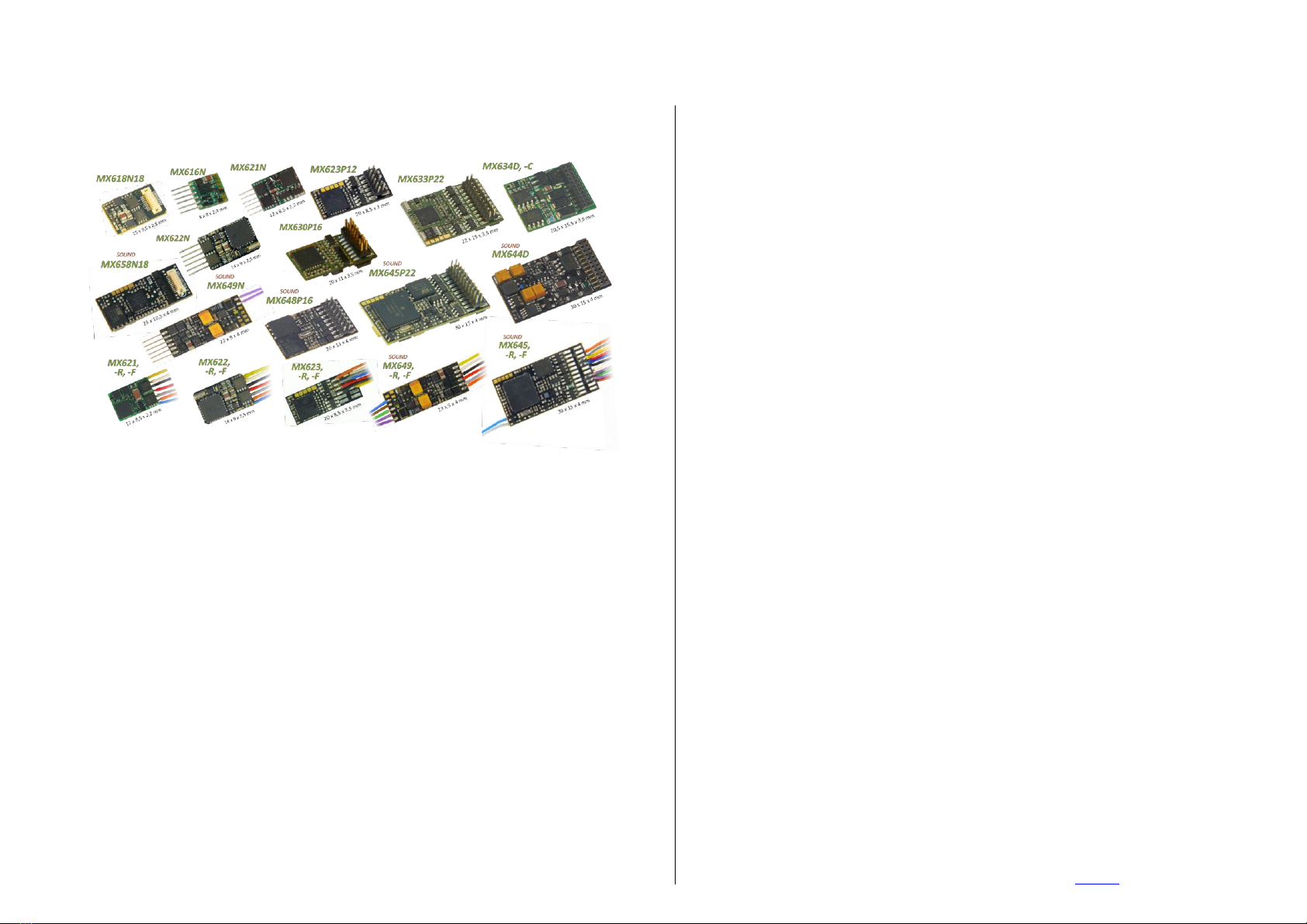
Dimensions (L x W x H) …... MX600, MX600P12 ............................................................. 25 x 11 x 2 mm
MX616 ................................................................................. 8 x 8 x 2.4 mm
MX617 ................................................................................ 13 x 9 x 2.6 mm
MX618 ............................................................................. 15 x 9,5 x 2.8 mm
MX620, MX620N (excluding pins) ....................................... 14 x 9 x 2.5 mm
MX621, MX621N (excluding pins) .................................... 12 x 8,5 x 2.2 mm
MX622, MX622P16 (height without pins) ............................ 16 x 9 x 2.5 mm
MX623, MX623P16 ......................................................... 20 x 8.5 x 3.5 mm
MX630, MX630P16 (height without pins) .......................... 20 x 11 x 3.5 mm
MX631, MX631D/C, MX634, MX634D/C ....................... 20.5 x 15.5 x 4 mm
MX632, MX632D .............................................................. 28 x 15.5 x 4 mm
MX633, MX633P22, MX637 ...............................................22 x 15 x 3.5 mm
MX635, MX636...................................................................26 x 15 x 3.5 mm
MX634, MX638.............................................................20.5 x 15.5 x 3.5 mm
MX646, MX646N ............................................................... 28 x 10.5 x 4 mm
MX648, MX648P16 (height without pins) .............................. 20 x 11 x 4 mm
MX648N, MX649N (without pins) ........................................... 23 x 9 x 4 mm
MX640 .............................................................................. 32 x 15.5 x 6 mm
MX642, MX643, MX644, MX645 ......................................... 30 x 15 x 4 mm
MX658 .............................................................................. 25 x 10.5 x 4 mm
MX659 ................................................................................ 20 x 9.5 x 3 mm
MX660 .................................................................................42 x 9 x 4.2 mm
Adapter boards ADAPLU -MTC
with decoder
......... 45 x 15 (26,5) x 4 (6) mm
*) The short circuit protection is carried out for the total current of all outputs. Use the “soft start” option (i.e. CV #125 = 52) to prevent
cold-start problems of light bulbs (in-rush current interpreted as a short circuit, which leads to the output being turned off)!
The decoder type can be read out in CV #250: 190=MX659 199=MX600 200=MX82 201=MX620
194=MX660 195=MX616 196=KISS Silberlinge 197 = MX617 198=FLM_E69
199= MX600 200=MX82 201=MX620 202=MX62 203=MX63
204=MX64 205=MX64H 206=MX64D 207=MX680 208=MX690
209=MX69 210=MX640 211=MX630-P2520 212=MX632 213=MX631
214=MX642 215=MX643 216=MX647 217=MX646 218=MX630-P25K22
219=MX631-P25K22 220=MX632-P25K22 221=MX645 222=MX644 223=MX621
224=MX695-RevB 225=MX648 226=MX685 227=MX695-RevC 228=MX681
229=MX695N 230=MX696 231=MX696N 232=MX686 233=MX622
234=MX623 235=MX687 236=MX621-FLM 237=MX633 238=MX820RevA
240=MX634 241=MX686B 242=MX820RevB 243=MX618 244=Roco NextG
245=MX697 246=MX658 247=MX688 248=MX821 249=MX648-RevC,D
250=MX699 251=Roco 2067 252=Roco ICE 253=MX649 254=MX697-RevB
Software Update:
ZIMO DCC decoders can be updated by the user. An update device such as the ZIMO decoder up-
date module MXDECUP, from 2011 MXULF, system-cab MX31ZL or command station MX10 is
required. The update process is carried out by a flash drive (MXULF, MX31ZL / MX10) or by a PC
with Windows operating system and the program ZIMO Firmware Flasher (in the bundle with ZSP).
The same hardware, but ZSP (software) is also used for uploading sound projects into ZIMO sound
decoders.
There is no need to remove the decoder or to open up the locomotive. Just set the locomotive on a
section of track connected to the update module and start the update with the computer or other
equipment mentioned above.
NOTE: Equipment inside the locomotive that is powered directly from the track (not through the de-
coder) can interfere with the update procedure. The same is valid for energy buffers that are in-
stalled without heeding the advice in the “Installation and wiring” chapter, section “Use of an external
energy source” (regarding a choke coil).
See the last chapter in this manual for more information on updating decoders or www.zimo.at!
Of course, SW updates can be done by ZIMO or your ZIMO dealer for a small fee.
Overload and Thermal Protection:
The motor and function outputs of ZIMO decoders are designed with lots of reserve capacities and
are additionally protected against excessive current draw and short circuits. Cut-outs are encoun-
tered if the decoder is overloaded.
Even though the decoder is well protected, it is not indestructible. Please pay attention to the following:
Wrong decoder contact, if, for instance, the motor leads have contact to track power or an overlooked connection
between the motor brushes and rail pick-ups is not always recognized by the overload protection circuit and could
lead to damage of the motor power amplifier or even a total destruction of the decoder.
Unfit or defective motors (e.g. shorted windings or commutator) are not always recognized by their high current
consumption, because these are often just short current spikes. So, they can lead to decoder damage including
damage to power amplifiers due to long-term exposure.
The power amplifiers of loco decoders (motor as well as function outputs) are not only at risk of overcurrent but al-
so voltage spikes, which are generated by motors and other inductive consumers. Depending on track voltage,
such spikes can reach several hundred volts and are absorbed by special protection circuits inside the decoder.
This is why the voltage shall not be too high, i.e. not higher than intended by the corresponding vehicle.
All ZIMO decoders are equipped with temperature sensors to measure their own operating temperature.
Power to the motor will be turned off once that temperature exceeds 1000C. The headlights start flashing
rapidly, at about 5 Hz, to make this state visible to the operator. Motor control will resume automatically af-
ter a drop in temperature of about 200C, typically in about 30 seconds.

Page 6 Non-Sound Decoder MX618 - MX638 and Sound Decoder MX640 - MX659

Non-Sound Decoder MX600 - MX638 and Sound Decoder MX640 - MX659 Page 7

Page 8 Non-Sound Decoder MX618 - MX638 and Sound Decoder MX640 - MX659
C versions differ from the
D versions in the design of
function outputs FO3 and
FO4:
MX631D: FO3 and FO4
outputs are “normal”
amplified outputs (same as
headlights, FO1 etc.).
MX631C: FO3 and FO4
are logic level outputs.
„C versions differ from the
D versions in the design of
function outputs FO3 and
FO4:
MX631D: FO3 and FO4
outputs are “normal”
amplified outputs (same as
headlights, FO1 etc.).
MX631C: FO3 and FO4
are logic level outputs.
Programm ing pads, do not touch!
MX 631D , C Top S ide
+5 V
Function output FO3
Function output FO2
Function output FO1
Commonpositive
Capacitor ground
Motorconnection1
Motorconnection2
Ground
Left rail
Right rail
Index pin
n.a.
n.a.
Front headlight
Rearheadlight
SUSI Data (FO6, Servo 2)
SUSI Clock (FO5, Servo 1)
Function output FO4
n.a.
n.a.
n.a.
MX 631 Bottom S ide
red
black
orange
gray
blue(+)
yellow
white
green
brown
Right rail
Left rail
Motorright
Motorleft
Commonpositive
Rearheadlight
Front headlight
Function output FO1
Function output FO2
Ground
Function output FO2
Function output FO1
Front headlight
Rearheadlight
Commonpositive(also cap. pos.)
Motorleft
Motorright
Left rail
Right rail
MX 631 Top S ide
Capacitor as
energy storage.
MX 631D , C Bottom S ide
Capacitor neg.
Attention:
DO NOT connect
to the Ground pad !
brown
green
white
yellow
blue
orange
black
red
SUSI D(FO6, Servo 2)
SUSI Cl(FO5, Servo 1)
Funct. FO4
+5 V
gray
Funct. FO3
Capacitor negative
(DO NOTconnect
capacitor toGround!)
Ground
>220 uF
35 V
- +
Programm ing pads, do not touch! Ground
>220 uF
35 V
- +
If not already
connectedthrough
the 21-pin plug:
Function output FO1
Function output FO2
Commonpos.
Capacitor
negative
Attention:
Do not connect
to Ground pad !

Non-Sound Decoder MX600 - MX638 and Sound Decoder MX640 - MX659 Page 9
M X633P22 To p V ie w with )( PluX22
Programmi ,ng pads
!do not touch
Functionoutput FO3
SUSIData(Servo2)
Capacitorpositive
Motorright
Motorleft
Railright
Railleft
Functionoutput FO1
Functionoutput FO2
Functionoutput FO5
Functionoutput FO7
Functionoutput FO8
Switchinput
SUSIClock(Servo1)
GROUND
Stirnl.vorne(=Lvor)
Commonpositive(+)
---(Index)
Rearlight(=Lrev)
---
Functionoutput FO8
Functionoutput FO4
Functionoutput FO6
Programming pads,
do not touch!
Function OutputFO4
Function OutputFO5
Function OutputFO6
Function OutputFO7
Function output FO1
Function output FO2
Left rail
Rear light (= Lrev)
Rail right
Motor right
Motor left
yellow
green
brown
orange
grey
red
black
Frontlight(=Lfor)
Com.pos.(+)
white
blue
Cap.pos.
GROUND
SUSIData (Servo 2) SUSIClock(Servo 1)
Switch input
Function outputFO3
>220uF
16 V
+ -
The SUSI outputscan alternatively
be used asservo outpus
M X6 33 w ith w ires To p Vie w
purple-purple
brown
green
white
yellow
blue(+)
gray
orange
black
red
Speaker - Speaker
Function output FO2
Common positive
Right rail
Function output FO1
Front headlight
Rear headlight
Motor left
Motor right
Left rail
M X 64 0 Top S id e
Program ming pads,
do not touch !
Switchinput1Switchinput2
5V, 200mApower supplyfor small servos (i.e. SmartServo) M X 64 0 Bo tto m S ide
F O 8 F O 9
FA5
FA6
FA7
F unc tion output s F O 4
F unc tion output F O 3
G round
SUSI Data
SUSI Clock
SUSI Positive
logic level outputs
ATT ENT I O N: connec t
LED (10 mA) - or
other side to Ground !
M X 64 0 D, C Top S ide
+5 V, 200 mAmax.
Function output FO3
Function output FO2
Function output FO1
Commonpositive
n.a.
Motorleft
Motorright
Ground
Left rail
Right rail
(= with 21-pin plug !)
Indexpin
Speaker
Speaker
Front headlight
Rearheadlight
SUSI Data
SUSI Clock
Function output FO4
n.a.
n.a.
Switch input 1
Program ming pads,
do not touch !
Switch input 1Switchinpout 2
5V, 200mA,for smallservo M X 64 0 D, C Bo tto m S ide
F O 8 F O 9
F O 5
F O 6
F O 7
F unc tion output F O 4
F unc tion output F O 3
G round
SUSI Data
SUSI Clock
SUSI Positive
ATTENTION:
The decoder can be
plugged in from either
side, depending on the
circuit board in the
locomotive.
logic level outputs
ATT ENT I O N: connec t
LED (10 mA) - or
other side to Ground !
(= where wires are soldered to)
(which is opposite to “normal” FO’s)
Function output FO3
Switch input
Function output FO4

Page 10 Non-Sound Decoder MX618 - MX638 and Sound Decoder MX640 - MX659
Speaker
Speaker
Function output FO2
Function output FO1
Front headlight
Rearheadlight
Common positive (also Cap. pos.)
Motorleft
Motorright
Left rail
Right rail
>220 uF
35 V
+ -
blue
Cap. pos.
Cap.
negative
MX 642 Top S ide
Capacitor as power back-up.
brown
green
white
yellow
blue
orange
black
red
+5V
purple
gra y
Capacitor negative
(This is not thesame
as theGroundterminal !)
gray
Attention:
DO NOT
connect this
wire to
Ground !
(is identical to
the common positive terminal)
Programming pads,
do not touch ! Function output FO3
SUSI D(FO8, Servo 2)
SUSI Cl(FO7, Servo 1)
Fu. output FO4
Fu. output FO5
Fu. output FO6
Ground
purple
Switchinput
MX 642 Bottom S ide
red
black
orange
gray
blue(+)
yellow
white
green
brown
purple
purple
Right rail
Left rail
Motorright
Motorleft
Common positive (also Cap. pos.)
Rearheadlight
Front headlight
Functionoutput FO1
Functionoutput FO2
Speaker
Speaker
>220 uF
35 V
+ -
blue
Cap. pos.
Cap.
negative
MX 642D, C Top S id e
Capacitor as power back-up.
gray
Attention:
DO NOT
connect this
wire to Ground !
(is identical to
the common positive terminal)
Programming pads,
do not touch !
(connect here if it isn’t already wired through the plug)
+5V (200mA)
Functionoutput FO3
2
1
Commonpositive
Capacitornegative
Motorconnection1
Motorconnection2
Ground
Left rail
Right rail
Functionoutput FO
Functionoutput FO
Index pin
Speaker
Speaker
Front headlight
Rearheadlight
SUSI Data(FO8, Servo2)
SUSI Clock (FO7, Servo 1)
4
5
6
Switchinput
Functionoutput FO
Functionoutput FO
Functionoutput FO
MX 642D, C Bottom S ide
(= wire side)
ATTENTION:
The decoder can be
plugged in from either
side, depending on
locomotive circuit board.
The SUSI outputs can alternatively be used
as servo, logic level or LED outputs (FO7, FO8);
LED‘s must be connected to Ground
(as opposed to “normal” outputs) !
MX 643P 22 Top S id e (w ith P luX 22)
Programming pads,
do not touch !
The SUSI outputs can alternatively
be used as servo outputs:
FO8 Functionoutput FO
Functionoutput FO
Functionoutput FO
Functionoutput FO
Functionoutput FO
3 Switchinput
SUSI Data(Servo2) SUSI Clock (Servo1)
ELKO Plus Ground
Motorrechts Front headlight
Motorlinks Common positive(+)
Schiene rechts ---
Schiene links Rearheadlight
1 Speaker
2 Speaker
5 FO4
7 FO6
(Index)
>220 uF
35 V
+ -
Cap.
pos. Cap.
neg.
(sameas
Ground)
MX 643P 16 Top S id e (w ith P luX 16)
Programming pads
do not touch !
The SUSI outputs can alternatively
be used as servo outputs:
SUSI Data(Servo2) SUSI Clock (Servo1)
Cap. pos. Ground
Motorright Front headlight
Motorleft Commonpoisitve(+)
Right rail ---
Left rail Rear headlight
1 Speaker
2 Speaker
(Index)
Functionoutput FO
Functionoutput FO
Capacitor as power back-up.
(if oneis mounted in lococircuit board, it is usually connected via theplug)

Non-Sound Decoder MX600 - MX638 and Sound Decoder MX640 - MX659 Page 11
Total capacity of all connected capacitor must not exceed 5000uF. NO gold cap pack (GOLM…)!
ATTENTION: Decoders installed by the loco
manufacturer (OEM versions) may have fewer function
otuputs than shown here (i.e. only headlights, FO1, FO2),
as the model requires.
Also see chapter 7, “Loco or adapter boards“
Total capacity of all connected capacitor must not exceed 5000uF. NO gold cap pack (GOLM…)!
FO9 and FO10 are logic level outputs
MX 645P 22 Top S ide (w ith P luX 22) The SUSI outputs can alternatively
be used as servo outputs:
Function output FO3 Switchinput
SUSI Data (Servo2) SUSI Clock (Servo 1)
Capacitorpositive Ground
Motorright Front headlight
Motorleft Commonpositive(+)
Right rail ---
Left rail Rear headlight
Function output FO1 Speaker
Function output FO2 Speaker
Function output FO5 FO4
Function output FO7 FO6
(Index)
>220 uF
20 V
+ -
Cap.
pos. Cap.
negative
(sameas
Ground)
MX 645P 16 Top S ide (w ith P luX 16 )
Programming pads,
do not touch ! The SUSI outputs can alternatively
be used as servo outputs:
SUSI Data (Servo2) SUSI Clock (Servo1)
Cap. pos. Ground
Motorright Front headlight
Motorleft Commonpositive(+)
Right rail ---
Left rail Rear headlight
Function output FO1 Speaker
Function output FO2 Speaker
(Index)
Capacitor as power back-up.
(is normally mountedonlococircuit boardandconnected viaplug)
Function output FO8
Programming pads,
do not touch !
Function output FO8
thesamefor MX645P22andMX645P16.
+ -
MX 645 w ires only To p S ide
Programming pads,
do not touch !
The SUSI outputs can alternatively
be used as servo outputs:
Function output FO1
Function output FO 2
Left rail
Rear headlight
Right rail
Motor right
Motor left
Front headlight
Commonpower(+)
Speaker
Speaker
purple
purple
White
blue
orange
gray
red
black
yellow
green
brown
SUSI Data (Servo 2) SUSI Clock(Servo 1)
Cap. pos.
Ground
Switchinput
Function output FO3
Function output FO
Function output FO
Function output FO
Function output FO
4
5
6
7
MX 645 Bottom S ide(all Types)
+5 V(200 mA)forServosetc. --connect to tantalum
>220 uF
20 V
+ -
Cap. neg.
Cap. pos.

Page 12 Non-Sound Decoder MX618 - MX638 and Sound Decoder MX640 - MX659

Non-Sound Decoder MX600 - MX638 and Sound Decoder MX640 - MX659 Page 13
3 Address and CV Programming
ZIMO decoders can be programmed in
- “Service Mode” (on the programming track) for assigning a new address or reading and
writing CV content, or in
- “Operations Mode” (a.k.a. “Programming on the main” or “PoM”), which is done on the
main track; programming CV’s “on the main” is always possible in operations mode. How-
ever, an acknowledgement of successful programming steps or reading out CV’s is only
possible with a RailCom capable DCC system.
HELPFUL HINTS FOR CV PROGRAMMING:
If you are familiar with CV programming please skip this section and go directly to section 3.1!
CV programming is not the same for all CV’s. While the programming procedure is the same for all
CV’s, the calculation of the individual CV values varies.
For some CV’s it is obvious what the value is supposed to be and can easily be derived from the
“Range” and/or “Description” column in the CV table. This kind of CV can be compared to volume
control.
For instance, CV#2 determines the minimum speed applied at speed step 1:
CV
Denomination
Range
Default
Description
#2
Vstart
1 –252
(See add.
notes)
2
Entered value = internal speed step assigned to
lowest cab speed step.
Bit 4 in CV # 29 has to be 0; otherwise individual
speed table is active.
The “range” column states that any value from 1 to 252 may be used. The higher the value the faster
the engine runs at speed step 1 and vice versa.
Another similar CV is the “dimming” factor in CV #60:
CV
Denomination
Range
Default
Description
#60
Reduced function
output voltage
(Dimming)
0 - 255
0
The actual function output voltage can be re-
duced by PWM. Useful to dim headlights, for ex-
ample.
Example values:
# 60 = 0 or 255: full voltage
# 60 = 170: 2/3 of full voltage.
# 60 = 204: 80% of full voltage.
Again, the range column states that any value from 1 to 252 may be used and in the “description” col-
umn it is explained that the brightness of the light increases with the value.
Other CV’s are easier to understand if you think of them as small switch boards, where you can turn
individual switches ON or OFF. Such a CV is made up of 8 “individual switches” called Bits and the
group of Bits is known as a Byte (which is the CV itself or the switch board, if you will). On some CV’s
you can change the setting of all 8 Bits (switches) and on others only a select few. The Bits (switches)
are numbered from 0 to 7 and each has a specific value (see the chapter “Converting binary to
decimal” for more on binary calculations). Each Bit is turned ON by adding its value to the CV and
turned OFF by subtracting its value. Add up the values of each Bit you want to turn ON and enter the
total to the CV.
One such CV is CV #29:
CV
Denomination
Range
Default
Description
#29
Basic
configuration
CV #29 is calculated by
adding the value of the
individual bits that are
to be “on”:
Values to turn “on”:
Bit 0: 1
Bit 1: 2
Bit 2: 4
Bit 3: 8
Bit 4: 16
Bit 5: 32
Bit 6: 64
Bit 7: 128
ZIMO MX21, MX31…
cabs also display the
individual bits;
calculating bit values is
no longer necessary!
0 - 63
14
Bit 0 - Train direction:
0 = normal, 1 = reversed
Bit 1 - Number of speed steps:
0 = 14, 1 = 28
Note: 128 speed steps are always active if corresponding in-
formation is received!
Bit 2 - DC operation (analog): *)
0 = off 1 = on
Bit 3 - RailCom („bidirectional communication“)
0 = deactivated
1 = activated see CV #28!
Bit 4 - Individual speed table:
0 = off, CV # 2, 5, 6, are active.
1 = on, according to CV ‘s # 67 – 94
Bit 5 - Decoder address:
0 = primary address as per CV #1
1 = ext. address as per CV #17+18
Bits 6 and 7 are to remain 0!
As explained in the description column of that CV, you can only change Bit 0, 1, 2, 3, 4 and 5. Bits 6
and 7 have to remain OFF (0) because they are not yet used for anything. To calculate the total CV
value you have to first look at the description field of that CV and determine which Bit (switch) you
want to have ON. Let’s say we want speed steps 28 active, reverse the loco’s direction because it
doesn’t agree with the cab’s direction indication and we want to use the individual speed table. This
means we have to have the Bits 1, 0 and 4 turned ON (= 1). All other Bits can be OFF (= 0). In the
“Denomination” field it shows the value for each Bit: Bit 0 = 1, Bit 1 = 2, Bit 2 = 4, Bit 3 = 8, Bit 4 = 16,
Bit 5 = 32, Bit 6 = 64, and Bit 7 = 128. If we want to have Bits 1, 0 and 4 turned ON we add up the
values for these Bits (2 + 1 + 16) and enter the total of 19 to CV #29.

Page 14 Non-Sound Decoder MX618 - MX638 and Sound Decoder MX640 - MX659
Lastly there is a third kind of CV that sort of fits between the other two. Here you don’t have to worry
about Bits and their values. With those CV’s the digit’s position and value determines a specific ac-
tion. Some of those digit positions act like a simple ON/OFF switch and others like a volume control.
For example, CV #56 can be used for fine-tuning a motor:
CV
Denomination
Range
Default
Description
#56
Back-EMF control
P and I value
0 –199
(See add.
notes)
0
(is equal
to 55,
mid-
range)
But:
default is
not suita-
ble for
coreless
motors,
i.e.
MAXXON,
FAUL-
HABER!
Use
“100”
instead.
Back-EMF compensation is calculated by PID al-
gorithm (Proportional/Integral - Differential);
modifying these values may improve the com-
pensation characteristics in certain cases.
0 - 99: for „normal“ DC motors (LGB etc.)
100 - 199: for coreless (MAXXON, Faulhaber,
etc...)
Tens digit: Proportional (P) value; by
default (0) is set to mid value and
automatic adjustment with the goal
of jerk free running. Proportional
effect can be modified with settings
of 1 –4 and 6 –10 (instead of the
default 0 = 5).
Ones digit: Integral (I) value; is set by
default to a mid-value.
The Integral effect can be modified
with settings of 1 –9 instead of
the default 0 = 5).
As you can see in the “Range” field you can use any number between 0 and 199. However if you read
the “Description” field it explains that each digit position controls a specific function. In this case, the
hundredth digit (_xx) sets the decoder up for a coreless motor, the tens digit (x_x) modifies the pro-
portional and the ones digit (xx_) the integral action. The hundredth digit acts just like a switch. If you
use the hundredth digit (1__) the coreless motor control is turned ON. If you don’t use it (_xx), the
function is turned OFF. So for a normal DC motor you would only use the ones and tenth digit. With
the tens digit (0 –9) you can modify the proportional value and with the ones digit (0 –9) the integral
value.
Don’t worry about the terms “proportional” or “integral” - just use the “Step by step CV adjustment
procedure” later in the manual.
3.1 Programming in “Service mode”(on programming track)
The decoder must be unlocked, before it is possible to program, with
CV #144 = 0 or = 128 (the latter prevents decoder updating but allows programming).
This is normally the case (CV #144 = 0), but the programming lock is often activated in many sound
projects to prevent accidental changes. It is therefore useful to check this CV, especially when pro-
gramming attempts have already failed.
Acknowledgments of successful programming steps as well as CV read-outs on the programming
track are accomplished by power pulses, which the decoder generates by briefly actuating the motor
and/or headlights. If the motor and/or headlights do not draw power (i.e. they are not connected) or
the power draw is too low, acknowledgments for successful programming or CV read-outs are not
possible.
To make acknowledgments possible in such cases activate CV #112 bit 1, which enables the decoder
to use an alternate acknowledgment method by sending high frequency pulses from the motor power
amplifier. It depends on the digital system in use, if this procedure is successful or not.
CV
Denomination
Range
Default
Description
#144
Programming and
Update Lock
Note: The programming
lock has no effect on
CV #144 and is there-
fore always accessible
for unlocking.
Bits
6, 7
0
or
255
= 0: Decoder unlocked. Free programming and
updating is possible.
Bit 6 = 1: Decoder programming in „Service Mode“ is
blocked to prevent unwanted programming.
Note: Programming in “Operations Mode“ is not
locked because any such programming only
applies to the active loco address and
reprogramming the wrong locomotive is
therefore not possible.
Bit 7 = 1: Software updates via MXDECUP, MX31ZL or
other means are blocked.
#112
Special ZIMO
configuration bits
0 - 255
4 =
00000100
that is
Bit 1 = 0
(normal)
Bit 1 = 0: Normal acknowledgment in “Service Mode“;
motor and headlight pulses.
= 1: High frequency pulses instead of normal
acknowledgments from motor and headlights.
Bit 2 = 0: Loco number ID is OFF etc.
Attention: The CV values of sound decoders at time of delivery do not correspond with the default
values in the following chapters, but rather the initial values of each loaded sound project!
This applies most often to
CV #29 –analog operation is usually turned off (Bit 3 = 0); CV #29 = 14 turns this on if desired.
CV #144 –the update lock may be activated (Bit 7 = 1), sometimes even the programming lock (Bit 6
= 1); before updating or programming a decoder, set this CV to CV #144 = 0.
CV #3, 4 –acceleration and deceleration CV’s are often set to higher values (i.e. 12).
CV #33 and following –the functions are often mapped to a specific loco model...
…and of course the sound CV’s (from CV #265) and (less frequently) all other CV’s.

Non-Sound Decoder MX600 - MX638 and Sound Decoder MX640 - MX659 Page 15
3.2 Programming in “Operational Mode”(on-the-main “PoM”)
According to the current NMRA DCC standards, it should only be possible to program and read CV’s
on the main track, but not assign new vehicle addresses. However, certain DCC systems (among
them ZIMO beginning with the system generation MX10/MX32) will allow addresses to be modified on
the main track with the help of bidirectional communication.
All ZIMO decoders are equipped with bidirectional communication (“RailCom”) and can therefore
(with a corresponding DCC system such as ZIMO MX31ZL and all devices of the new MX10/MX32
generation) read, program and acknowledge successful CV programming steps in operations mode
(on the main track). This requires RailCom to be activated, which is the case if the following CV’s are
set as: CV #29, Bit 3 = 1(usually CV #29 = 14) AND CV #28 = 3
This is usually the default setting, except in certain sound projects or OEM CV sets, where they need to
be set prior to all other programming.
3.3 Decoder-ID, Load-Code, Decoder-Type and SW-Version
CV
Denomination
Range
Default
Description
#250,
#251,
#252,
#253
Decoder-ID
Also identifies decoder
type with
CV #250 = Decoder
type
(see chapter 2)
Read only
-
The decoder ID (serial number) is automatically entered
during production: The first Byte (CV #250) denotes the
decoder type; the three other Bytes contain the serial
number.
The decoder ID is primarily used for automatic address
assignment when an engine is placed on the layout
track (future function) as well is in conjunction with the
“load code” for “coded” sound projects (see CV #260-
CV
Denomination
Range
Default
Description
263).
#260,
#261,
#262,
#263
“Load code”
for
“coded” sound projects
-
-
New ZIMO sound decoders can be ordered for a small
fee with the “load code” pre-installed, which entitles the
user to install “coded” sound projects of a selected
sound bundle.
The load code can also be purchased and installed by
the user at a later date: see www.zimo.at.
#8
Manufacturer ID
and
HARD RESET
with CV #8 = 8
or CV #8 = 0
or
Configure decoders as “C-type” or
“D-type” (MX634 only):
MX634D:
FO3,FO4 = normal outputs
MX634C:
FO3,FO4 = logic level outputs
Activate Special CV Set
Read only
Reading out
the decoder
always shows
“145”, which is
ZIMO’s
assigned
number.
For pseudo
programming
see “Descrip-
tion” column
on the right.
145
( = ZIMO)
Reading out this CV always result in “145”
(”10010001”), the number issued for ZIMO by the
NMRA.
This CV is also used for various resetting processes
with the help of Pseudo-Programming.
Pseudo-Programming means that the entered value is not really stored, but
rather used to start a defined action.
CV #8 = “3” Converting a MX634D to MX634C
CV #8 = “4” Converting a MX634C to MX634D
CV #8 = “8” HARD RESET(NMRA standard);
all CV’s return to the last active CV set or sound
project, or the default values listed in this CV table if
no such set was active before.
CV #8 = “9” HARD RESET for LGB-MZS operation
(14 speed steps, pulse chain commands).
Further options: see chapter “CV Sets”!
#7
SW-Version Number
Also see CV #65 for
Sub-Version Number
and
special procedures for pro-
gramming with “Lokmaus-2”
and other “low level” sys-
tems
Read only
Pseudo-
programming
see explana-
tion to the right
-
This CV holds the firmware version number currently in
the decoder.
With the help of “Pseudo-programming” it also helps to
program decoders with DCC systems of limited range:
Ones digit = 1: Subsequent programming value + 100
= 2: ... + 200
Tens digit = 1: Subsequent CV number + 100
= 2: … + 200
etc. = 9: … + 900
Hundreds digit = 0: Revaluation applies only once
= 1: … until power-off
#65
SW-
Sub-Version Number
Also see CV #7 for
main version number
Read only
-
This CV indicates a possible sub-version number of a
main version noted in CV #7.
The entire SW version number is thus composed of
CV #7 and #65 (i.e. 28.15).
3.4 The vehicle address(es) in DCC mode
Decoders are usually delivered with default address 3 (CV #1 = 3), for the DCC as well as the MM
(Märklin Motorola) format. All aspects of operations are possible with this address but it is recom-
mended to change to a different address as soon as possible.
CV
Denomination
Range
Default
Description
#28
RailCom Configuration
0 - 3
3
Bit 0 - RailCom Channel 1 (Broadcast)
0 = OFF 1 = ON
Bit 1 - RailCom Channel 2 (Data)
0 = OFF 1 = ON
#29
Basic settings
0 - 63
14 =
0000 1110
Bit 3 = 1
(“RailCom” is
switched on)
and
Bits
1 & 2 = 1
(28 or 128
speed steps
and DC op-
eration ena-
bled)
Bit 0 - Train direction:
0 = normal, 1 = reversed
Bit 1 - Number of speed steps:
0 = 14, 1 = 28
Bit 2 - DC operation (analog): *)
0 = disabled 1 = enabled
Bit 3 - RailCom („bidirectional communication“)
0 = deactivated 1 = activated
Bit 4 - Individual speed table:
0 = off, CV # 2, 5 and 6 are active.
1 = on, according to CV ‘s # 67 – 94
Bit 5 - Decoder address:
0 = primary address as per CV #1
1 = ext. address as per CV #17&18

Page 16 Non-Sound Decoder MX618 - MX638 and Sound Decoder MX640 - MX659
The address space required for DCC exceeds the range of a single CV, up to 10239 in fact. Address-
es higher than 127 are stored in CV #17 and #18. Bit 5 in CV #29 is used to select between the short
address in CV #1 and the long address in CV’s #17/18.
Most digital systems (with the possible exception of very old or simple products) automatically calcu-
late the value for the CV’s involved and also set Bit 5 in CV #29 to the proper value when writing the
address, so that the user does not have to deal with the necessary coding.
CV
Denomination
Range
Default
Description
#1
Short Address
DCC:
1 - 127
MM:
1 - 80
3
The “short” (1-byte) loco address (DCC,MM)
In the case of DCC:
The address in CV #1 is only valid if CV #29, Bit 5 = 0.
Otherwise, if CV #29 Bit 5 = 1, the long address in CV
#17 + #18 applies.
#17
+
#18
Extended (long)
address
128
-
10239
0
The long DCC address applies to addresses >127.
It is only active if CV #29 Bit5 = 1.
#29
Basic Configuration
0 - 63
14 =
0000 1110
with
Bit 5 = 0
(for short
address)
Bit 0 - Train direction:
0 = normal, 1 = reversed
Bit 1 - Number of speed steps:
0 = 14, 1 = 28
Bit 2 - DC operation (analog): *)
0 = disabled 1 = enabled
Bit 3 - RailCom („bidirectional communication“)
0 = deactivated 1 = activated
Bit 4 - Individual speed table:
0 = off, CV # 2, 5 and 6 are active.
1 = on, according to CV ‘s # 67 – 94
Bit 5 - Decoder address selection:
0 = short address as per CV #1
1 = long address as per CV #17+18
Decoder-controlled consisting (a.k.a. “Advanced consisting”)
The combined operation of two or more locomotives (consisting) can be managed by
- the DCC system (common practice with ZIMO systems, without changing any decoder CV’s) or
- by programming the following decoder CV’s individually, but can also be managed by some
DCC systems (often the case with American made systems).
This chapter only covers the decoder-controlled consisting!
CV
Denomination
Range
Default
Description
#19
Consist address
0,
1 –127
129 - 255
( = 1 - 127
with
inverted
direction )
0
A common consist address for 2 or more engines can
be entered in this CV to each loco of the same consist.
If CV #19 > 0: Speed and direction is governed by this
consist address (not the individual address in CV #1 or
#17&18); functions are controlled by either the consist
address or individual address, see CV’s #21 & 22.
CV
Denomination
Range
Default
Description
Bit 7 = 1: Driving direction reversed
#20
Extended consist
address
From SW version 36.6
0 - 102
0
The value of CV20 multiplied with 100 added together
with the value of CV 19 which result is the address at
consist.
e.g. CV20= 12, CV19=34 is address. 1234
CV20=100, CV19=00 is address 10000
#21
Consist functions
F1 - F8
0 - 255
0
Functions so defined here will be controlled by the con-
sist address.
Bit 0 = 0: F1 controlled by individual address
= 1: …. by consist address
Bit 1 = 0: F2 controlled by individual address
= 1: …. by consist address
………. F3, F4, F5, F6, F7
Bit 7 = 0: F8 controlled by individual address
= 1: …. by consist address
#22
Consist Functions
F9 –F27
and
headlight control
0 - 191
0
Select whether the headlights are controlled with the
consist address or individual address.
Bit 0 = 0: F0 (forw.) controlled by individual address
= 1: …. by consist address
Bit 1 = 0: F0 (rev.) controlled by individual address
= 1: …. by consist address
Bit 2 = 0: F9 controlled by individual address
= 1: …. by consist address
Bit 3 = 0: F10 controlled by individual address
= 1: …. by consist address
Bit 4 = 0: F11 controlled by individual address
= 1: …. by consist address
Bit 5 = 0: F12 controlled by individual address
= 1: …. by consist address
Bit 7 = 1: F13 –F27 (all!) ….by consist address
Bit 6 = 1: SW-Version 37.0 and later! Auto-Consist: The
system changes automatically between individual and
consist address, if one of the two addresses has speed
0 and the other has speed >0.
3.5 Analog operation
All ZIMO decoders are capable of operating on conventional layouts with DC power packs, including
PWM throttles, in analog DC as well as in analog AC (Märklin transformers with high voltage pulse for
direction change).
To allow analog operation CV #29, Bit 2 = 1
must be set. This is usually the case by default (CV #29 = 14, which includes Bit 2 = 1), but analog op-
eration may be turned off in many sound projects (sound decoders). It is recommended to turn ana-
log mode off when operating strictly on DCC!
The actual behavior during analog operation, however, is strongly influenced by the locomotive con-
troller (power pack). Especially in conjunction with a weak transformer, it is easily possible that the

Non-Sound Decoder MX600 - MX638 and Sound Decoder MX640 - MX659 Page 17
track voltage collapses when the decoder (motor) starts to draw power which, in the worst case, may
lead to intermittent performance.
There are some adjustment possibilities for analog operation where motor control and function out-
puts are concerned; these CV’s can of course be read-out or programmed only with a DCC system or
other programming device.
CV
Denomination
Range
Default
Description
#29
Basic Configuration
0 - 63
14 =
0000 1110
Bit 2 = 1
(enables
analog op-
eration)
Bit 0 - Train direction:
0 = normal, 1 = reversed
Bit 1 - Number of speed steps:
0 = 14, 1 = 28
Bit 2 –Automatic DC operation (analog): *)
0 = disabled 1 = enabled
Bit 3 - RailCom („bidirectional communication“)
0 = deactivated 1 = activated
Bit 4 - Individual speed table:
0 = off, CV # 2, 5 and 6 are active.
1 = on, according to CV ‘s # 67 – 94
Bit 5 - Decoder address selection:
0 = short address as per CV #1
1 = long address as per CV #17+18
#13
Analog functions
F1…F8
0 - 255
0
Defines functions that should be “ON” in analog mode.
Bit 0 = 0: F1 is OFF in analog mode
= 1: …ON in analog mode
Bit 1 = 0: F2 is OFF in analog mode
Bit 1 = 1: …ON in analog mode
………..F3, F4, F5, F6, F7
Bit 7 = 0: F8 is OFF in analog mode
Bit 7 = 1: …ON in analog mode
#14
Analog functions
F0 v&r, F9 –F12,
Analog momentum
and
Regulated Analog
0 - 255
64
(equals
Bit 6 = 1)
Defines function outputs that should be “ON” in analog
mode.
Bit 0 = 0: F0 (forw) is OFF in analog mode
= 1: …ON in analog mode
Bit 1 = 0: F0 (rev) is OFF in analog mode
Bit 1 = 1: …ON in analog mode
Bit 2 = 0: F9 is OFF in analog mode
Bit 2 = 1: …ON in analog mode
------------F10, F11, F12
Bit 6 = 0: Analog operation with acceleration and
deceleration according to CV #3 and #4,
especially useful for sound
Bit 6 = 1: Analog operation without acceleration and
deceleration according to CV #3 and #4.
Bit 7 = 0: unregulated DC operation
Bit 7 = 1: regulated DC operation
Note: Actual decoder settings may differ from the default values if a sound project is on the decoder; in particular,
the motor regulation (CV #14, Bit 7) is often enabled. The regulation only works well with power packs that apply
“clean” DC voltage (i.e. with an LGB 50 080); otherwise it is better to turn the motor regulation off.
3.6 Motor Regulation
The speed curve
There are two types of speed curves, which are selected with
CV #29, Bit 4 = 0: 3-step curve (defined by 3 CV’s)
... = 1: 28-step curve (defined by 28 CV’s)
3-point speed table: the lowest, highest and medium speed is defined by the Configuration Variables
#2 (Vstart), #5 (Vhigh) and #6 (Vmid) (=external speed step defined by slider position). This is a sim-
ple way to quickly establish a speed range and its curvature.
The three-step curve is usually sufficient.
28-point speed table (a.k.a. ”free programmable speed table”): with the help of CV’s #67 - 94, all 28
external speed steps can be freely assigned to the 128 internal speed steps. These 28 CV’s apply to
all speed step modes (14, 28 and 128). If 128 external speed steps are used, the decoder adds the
missing intermediate values by interpolation.
CV
Denomination
Range
Default
Description
#2
Start Voltage
Vstart
with 3-point table if
CV #29, Bit 4 = 0
1 - 255
1
Internal speed step (1 … 255) applied as
lowest external speed step (= speed step 1)
(applies to 14, 28, or 128 speed step modes)
= 1: lowest possible speed
#5
Top Speed
Vhigh
with 3-step curve if
CV #29, Bit 4 = 0
0 - 255
0, 1
corresponds
to
255
Internal speed step (1 … 255) applied as
highest external speed step
(14, 25 or 128, depending on the speed step mode
selected in CV # 29, Bit 1)
=0 = 1 (same as 255): fastest top speed possible.
0
10
20
30
40
50
60
70
80
90
100
110
120
130
140
150
160
170
180
190
200
210
220
230
240
250
0 1 2 3 4 5 6 7 8 9 10111213141516171819 202122232425262728
0 9 18 27 36 45 54 63 72 81 90 99 108 117 1 26
Example of a freely
programmed speed
curve according to
the values entered
in to configuration
variables #67 - 94.
0
10
20
30
40
50
60
70
80
90
100
110
120
130
140
150
160
170
180
190
200
210
220
230
240
250
0 1 2 3 4 5 6 7 8 9 10111213141516171819 202122232425262728
0 9 18 27 36 45 54 63 72 81 90 99 108 117 1 26
Clipped and bent speed curve
Vstart = 15, Vhigh = 180, Vmid = 60
0
10
20
30
40
50
60
70
80
90
100
110
120
130
140
0 1 2 3 4 5 6 7 8 9 10111213141516171819 202122232425262728
0 9 18 27 36 45 54 63 72 81 90 99 108 117 1 26
Clipped linear speed curve
Vstart = 10, Vhigh = 165,
Vmid = 90
150
160
170
180
190
200
210
220
230
240
250
0
10
20
30
40
50
60
70
80
90
100
110
120
130
140
0 1 2 3 4 5 6 7 8 9 10111213141516171819 202122232425262728
0 9 18 27 36 45 54 63 72 81 90 99 108 117 1 26
Linearcharacterisit
c-Vstart=1,Vhigh
=252,Vmid=127
Slightly bent
(default) characterisitc
Vmid = 1 (equals85)
Vstart = 2
Vhigh = 1
(equals252)
Center
150
160
170
180
190
200
210
220
230
240
250
Internal speed step
External speed step

Page 18 Non-Sound Decoder MX618 - MX638 and Sound Decoder MX640 - MX659
CV
Denomination
Range
Default
Description
#6
Medium Speed
Vmid
1,
¼ to ½
of the val-
ue in
CV #5
1
(= @ 1/3 of top
speed)
Internal speed step (1 … 255) applied as
medium external speed step (that is, speed step
7, 14 or 64 depending on the speed step mode se-
lected in CV #29, Bit 1)
”1" = default (Medium speed is set to one third of top
speed. I.e., if CV #5 = 255 the curve is the same as if
CV #6 would be programmed to 85).
The speed curve resulting from CV #2, 5 and 6 is au-
tomatically smoothed out.
#29
Basic
configuration
0 - 63
14 =
0000 1110
with Bit 4 = 0
(3-speed step)
Bit 0 - Train direction:
0 = normal, 1 = reversed
Bit 1 - Number of speed steps:
0 = 14, 1 = 28/128
Bit 2 - DC operation (analog): *)
0 = disabled 1 = enabled
Bit 3 - RailCom („bidirectional communication“)
0 = deactivated 1 = activated
Bit 4 - Individual speed table:
0 = off, CV # 2, 5 and 6 are active.
1 = on, according to CV ‘s # 67 – 94
Bit 5 - Decoder address: 0 = primary address
as per CV #1 1 = ext. address as per CV
#17+18
#67
.…..
#94
Individual speed table,
if CV #29, Bit 4 = 1
0 - 255
*)
User programmable speed table.
Each CV corresponds to one of the 28 external speed
steps that can be “mapped” to internal steps (1 –
255).
*) The 28-point default curve is also bent in the lower
speed range.
#66
#95
Directional
speed trimming
0 - 255
0 - 255
0
0
Speed step multiplication by “n/128”
(n is the trim value in this CV)
#66: for forward direction
#95: for reverse direction
The reference voltage for motor regulation
CV # 57 specifies the base voltage used for motor regulation. For example: if 14V is selected (CV
value: 140) the decoder tries to send the exact fraction of this voltage, determined by the speed regu-
lator position, to the motor, regardless of the voltage level at the track. As a result the speed remains
constant even if the track voltage fluctuates, provided the track voltage (more precisely, the rectified
and processed voltage inside the decoder, which is about 2V lower) doesn’t fall below the absolute
reference voltage.
The default value “0” in CV #57 selects the “relative reference”, which automatically adjusts the refer-
ence voltage to the available track voltage. This setting is only useful if the system can keep the track
voltage constant at all times (stabilized track output) and the resistance along the track kept to a mini-
mum. All ZIMO systems keep the track voltage stable even older systems, but not every system from
other manufacturers do, especially the relatively cheap systems built before 2005. It is not recommend-
ed to set CV #57 to “0” with systems that don’t keep track voltage stabilized. Instead set this CV about
2V below track voltage (i.e. 140 for 16V).
CV #57 can also be used as an alternative to CV #5 (top speed), which has the advantage that the full
resolution of the 255 speed steps remains available.
CV
Denomination
Range
Default
Description
#57
Voltage reference
0 - 255
0
Absolute voltage in tenth of a volt applied to the motor
at full speed (max. throttle setting).
Example: A system from another manufacturer is set
to 22V at idle but drops to 16V under load: A good set-
ting would be CV #57 = 140…150.
CV #57 = 0: automatically adjusts to the track voltage
(relative reference); only useful with stabilized track
voltage.
Tweaking the motor regulation
The motor’s performance, especially at crawling speeds (as judder-free as possible), can be fine-
tuned with the following CV’s:
CV #9 –Motor control frequency and EMF sampling rate
The motor is controlled by pulse with modulation that can take place at either low or high frequency.
Low frequency (30 –159Hz) is only useful for very few locomotives with very old motors (i.e. AC mo-
tors with field coils instead of permanent magnets).
High frequency (20 kHz by default, up to 40 kHz as per CV #112) on the other hand is quiet and
easy on the motor.
Power to the motor is interrupted periodically (50 –200 times/sec.), even when operating at high fre-
quency, in order to determine the current speed by measuring back-EMF (voltage generated by the
motor). The more frequent this interruption takes place (sampling rate), the better; but that also caus-
es power loss and increased noise. By default, the sampling frequency varies automatically between
200Hz at low speed and 50 Hz at maximum speed.
CV #9 allows the adjustment of the sampling frequency (tens digits) as well as the sampling time
(ones digits). The default value of 55 represents a medium setting.
CV # 56 –The PID regulation
The motor regulation can be tailored to motor type, vehicle weight and so on, by using different Pro-
portional-Integral-Differential values. In reality, changing the differential value can be omitted.
CV #56 allows the proportional value (tens digit) as well as the integral value (ones digit) to be set in-
dividually. The default value of 55 represents a medium setting.
CV
Denomination
Range
Default
Description
#9
Motor control frequency
and
EMF sampling
(Algorithm)
55
High
frequency,
medium
sampling
55
High
frequency,
medium
scanning
= 55: Default motor control with high frequency
(20/40kHz), medium EMF sampling rate that automati-
cally adjusts between 200Hz (low speed) and 50Hz and
medium EMF sampling time.
<> 55: Modification of automatic adjustments with:

Non-Sound Decoder MX600 - MX638 and Sound Decoder MX640 - MX659 Page 19
0
10
20
30
40
50
60
70
80
90
100
110
120
130
140
150
160
170
180
190
200
210
220
230
240
250
0 20 40 60 80 1 00 150 20 0 252
Defaultcompensationcurve
CV#58=255,CV#10und#113=0
Fullcompensationatlowspeed,
droppingoffto0atfullspeed.
Comp. influence
Int.s peed s tep
Alteredcompensationcurve
CV#58=180,CV#10und#113=0
Reducedcompensationover
thewholespeedrange.
0
10
20
30
40
50
60
70
80
90
100
110
120
130
140
150
160
170
180
190
200
210
220
230
240
250
0 20 40 60 80 100 150 200 252
Defaultcompensationcurve
Alteredcompensationcurve
CV#10=126,CV#113=200,
Increasedcompensation
inthemedium
speedrange.
#9
rate
.
01 - 99
High
frequency
with
modified
sampling
rate.
255-176
Low
frequency
rate
.
tens digit for sampling rate and
ones digit for sampling time.
Tens digit 1 - 4: Lower sampling rate than default
(less noise!)
Tens digit 6 - 9: Higher sampling rate than default
(to combat juddering!)
Ones digit 1 –4: Shorter EMF sampling time
(good for coreless motors, less noise, more power)
Ones digit 6 - 9: Longer EMF sampling time
(may be needed for round motors or similar).
Typical test values against jerky driving:
CV #9 = 55 (default) 83, 85, 87, ...
CV #9 = 55 (default) 44, 33, 22, …
= 255 - 176: Low frequency (for old motors only!) –
PWM according to formula (131+ mantissa*4) *2exp. Bit 0-4 is
“mantissa”; Bit 5-7 is “exp”. Motor frequency is the reciprocal of
the PWM.
Examples:
#9 = 255: frequency at 30 Hz,
#9 = 208: frequency at 80 Hz,
#9 = 192: frequency at 120 Hz.
#112
Special ZIMO
configuration bits
0 - 255
4 =
0000 0100
Bit 1 = 0: Normal acknowledgement.
= 1: High frequency acknowledgement
Bit 2 = 0: Loco number recognition OFF
= 1: ZIMO loco number recognition ON
Bit 3 = 0: 12-Function Mode
= 1: 8-Function Mode
Bit 4 = 0: Pulse chain recognition OFF
= 1: Pulse chain recognition (for old LGB)
Bit 5 = 0: 20 kHz motor control frequency
= 1: 40 kHz motor control frequency
Bit 6 = 0: normal (also see CV #29)
= 1: „Märklin brake mode
#56
P and I value
For
BEMF motor regulation
55
medium
PID
setting
01 - 199
modified
settings
55
= 55: Default setting using medium PID parameters.
= 0 - 99: Modified settings for “normal” DC motors.
= 100 - 199: Modified settings for coreless motors
(Faulhaber, Maxxon etc.)
Tens digit 1 - 4: Lower proportional value than default
Tens digit 6 - 9: Higher proportional value than default
Ones digit 1 - 4: Lower integral than default
Ones digit 6 - 9: Higher integral than default
Typical test values against jerky driving:
CV #56 = 55 (default) 33, 77, 73, 71, ..
#147
EMF –Extended
sampling time
0 - 255
0
Useful initial test value: 20.
For Fleischmann motors
Values too small cause engine to stutter, values too big
worsens the regulation at low speeds.
Fine-tuning suggestions (if default settings are not satisfactory):
Vehicle, Type of Motor
CV #9
CV #56
Remarks
“Normal” modern Roco engine
= 95
= 33
Means high sampling rate at low load; reduced rate at
higher load to prevent loss of power.
Typical N-scale engine
= 95
= 55
Fleischmann “round motor”
= 89
= 91
Also recommended: CV #2 = 12, CV #147 = 60
From SW version 31: CV #145 = 2
(Attention: often helpful –remove suppressor compo-
nents.
Small coreless (Faulhaber, Maxxon
or similar)
= 51
= 133
The stronger the motor, the weaker the regulation is
set to avoid overshoots, the integral component never-
theless provides for full load regulation.
Large coreless (O gauge or larger)
= 11
= 111
Tips on how to find the optimal CV #56 settings:
Start with an initial setting of CV #56 = 11; set the engine at low speed while holding it back with one
hand. The motor regulation should compensate for the higher load within half a second. If it takes
longer than that, increase the ones digit gradually: CV #56 = 12, 13, 14...
With the locomotive still running at a low speed, increase the tens digit in CV #56. For example: (if the
test above resulted in CV #56 = 13) start increasing the tens digit CV #56 = 23, 33 ,43…as soon as
juddering is detected, revert back to the previous digit this would be the final setting.
Load Compensation, Compensation Curve and Experimental CV’s
The goal of load compensation, at least in theory, is to keep the speed constant in all circumstances
(only limited by available power). In reality though, a certain reduction in compensation is quite often
preferred.
100% load compensation is useful within the low speed range to successfully prevent engine stalls or
run-away under light load. Load compensation should be reduced as speed increases, so that at full
speed the motor actually receives full power. Also, a slight grade-dependent speed change is often
considered more prototypical.
Locomotives operated in consists should never run at 100% load compensation, in any part of the
speed range, because it causes the locomotives to fight each other and could even lead to derail-
ments. The overall intensity of load compensation can be
defined with CV # 58 from no compensation
(value 0) to full compensation (value 255). Useful
values range from 100 to 200.
For a more precise or more complete load com-
pensation over the full speed range use CV #10
and CV #113 together with CV #58 to define a 3-
point curve.

Page 20 Non-Sound Decoder MX618 - MX638 and Sound Decoder MX640 - MX659
CV
Denomination
Range
Default
Description
#58
BEMF intensity
0 - 255
255
Intensity of back-EMF control at the lowest speed step.
If required, an “intensity curve” can be achieved using
CV #10, 58 and 113 to reduce load regulation at higher
speeds.
Example:
# 58 = 0: no back-EMF
# 58 = 150: medium compensation,
# 58 = 255: maximum compensation.
#10
Compensation cut-off
This CV is seldom required
0 - 252
0
Assigns an internal speed step where back EMF inten-
sity is reduced to the level defined in CV #113. CV #10,
#58 and #113 together define a back-EMF curve.
= 0: default curve is valid (as in CV #58).
#113
Compensation cut-off
This CV is seldom required
0 - 255
0
The BEMF intensity is reduced to this value at the
speed step defined in CV #10.
CV #113 together with CV’s #58 and #10 form a 3-point
BEMF curve.
= 0: actual cutoff at speed step in CV #10. Usually
CV #10 is also set to 0.
#145
#147
#148
#149
#150
Experimental CV’s for
test purposes,
to find out whether
certain automatic
settings have a negative
effect on motor
regulation.
Using these
experimental CV’s will
deactivate the automatic
settings.
CV’s #147 – 149 will
likely be removed again
from the decoder SW at
some time.
CV #145 = 10,11,12,13
for C-Sinus motors
See chapter 6 (Installa-
tion)
0
0
0
0
0
--- CV #145 = 1: Special setting for Fleischmann round
motor.
--- CV #147 Sampling time ---
Useful initial value: 20;
Too small a value leads to jerky behavior.
Too large a value leads to poor low speed control.
0= automatic control (CV #147 has no effect)
--- CV #148 D-Value ---
Useful initial value: 20;
Too small a value leads to poor regulation (regulates
too little, too slow, engine judders (rather slowly).
Too large a value leads to over compensation, the en-
gine runs rough/vibrates.
0 = automatic control (CV #148 has no effect)
--- CV #149 P-Value ---
0 = automatic control (CV #149 has no effect)
1 = P-Value is fixed as per CV #56 (tens digit)
--- CV #150 Load compensation at top speed ---
Load compensation at top speed is normally always 0.
This can be changed with CV #150.
Example: CV #58 = 200, CV #10 = 100, CV #113 = 80
und CV #150 = 40 --> Result: Regulation at speed
step 1 is 200 (of 255, almost 100%), at speed step 100
it is 80 (@1/3rd of 255), at speed step 252 (full speed) it
is 200 (of 255, almost fully regulated).
We kindly ask for your cooperation. Please send us
your test results!
The Motor Brake
This brake is useful for vehicles without worm gears to prevent them from rolling away on inclines, picking up speed
on declines as well as to prevent a heavy train from pushing a standing engine downhill.
CV
Denomination
Range
Default
Description
#151
Motor brake
0 - 99
0
= 0: brake not active
Ones digit: 1 - 9: The motor brake is gradually actuat-
ed (over a period of 1, 2 … 8 seconds, up to full brak-
ing power by shorting both motor power amplifier) if
target speed is not reached (not slowing down) after
cutting power to the motor (Zero PWM to the motor).
The higher the value, the faster and harder the brake
is being applied.
Tens digit: 1-9: Reduction of the motor regulation if
consist-key is active. The values 1-9 reduce the con-
trol to 10%-90% of the value set in CV #58.
3.7 Acceleration and Deceleration:
The basic acceleration and deceleration times (momentum) are set with
CV’s #3 and #4
according to the relevant NMRA standard, which demands a linear progression (the time between
speed step changes remains constant over the whole speed range). For simple smooth drivability use
values 3 or higher but for really slow starts and stops start with a value of 5. Values over 30 are usual-
ly impractical!
Acceleration and deceleration behavior, especially starting and stopping, can be further improved by
the “exponential” and “adaptive” acceleration/deceleration features (CV’s #121, 122 and 123).
The sound project in sound decoders always comes with different values in CV’s #3 and #4 (as well as
many other CV’s) than what is listed in the CV charts. Often the sound can only be played back correct-
ly in conjunction with the acceleration times provided by the sound project (or certain minimum values),
so the sound project’s default values should therefore not be changed too much.
To eliminate a start-up jolt after changing the direction, caused by gear backlash in gearboxes, use
CV #146: Some free play between gears of a drivetrain is essential to prevent them from binding. This
creates backlash and may be more severe on some engines than on others, especially when fitted
with a worm gear or an excessively worn gearbox.
CV
Denomination
Range
Default
Description
#3
Acceleration rate
0 - 255
(2)
The value multiplied by 0.9 equals’ acceleration time in
seconds from stop to full speed.
The effective default value for sound decoders is usual-
ly not the value given here, but is determined by the
loaded sound project.
This manual suits for next models
106
Table of contents
Other ZIMO Media Converter manuals
Popular Media Converter manuals by other brands

Quatech
Quatech SS-CVT-500N Specifications

Baumer
Baumer HOGS 75 K Installation and operating manual

epcom TITANIUM
epcom TITANIUM TTBNCVGA quick start guide

Musical Fidelity
Musical Fidelity M1 DAC Instructions for use

Dometic
Dometic COOLPOWER MPS50 Installation and operating manual

WFCO
WFCO WF-984S Operator's manual