7
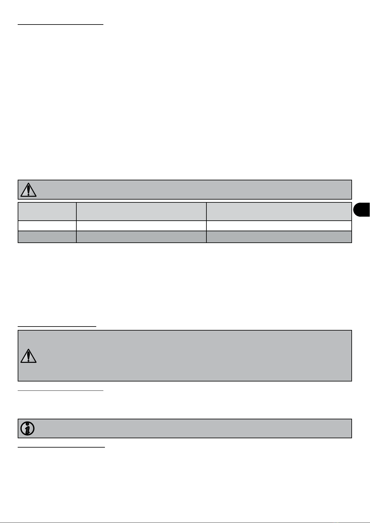
5. Troubleshoong
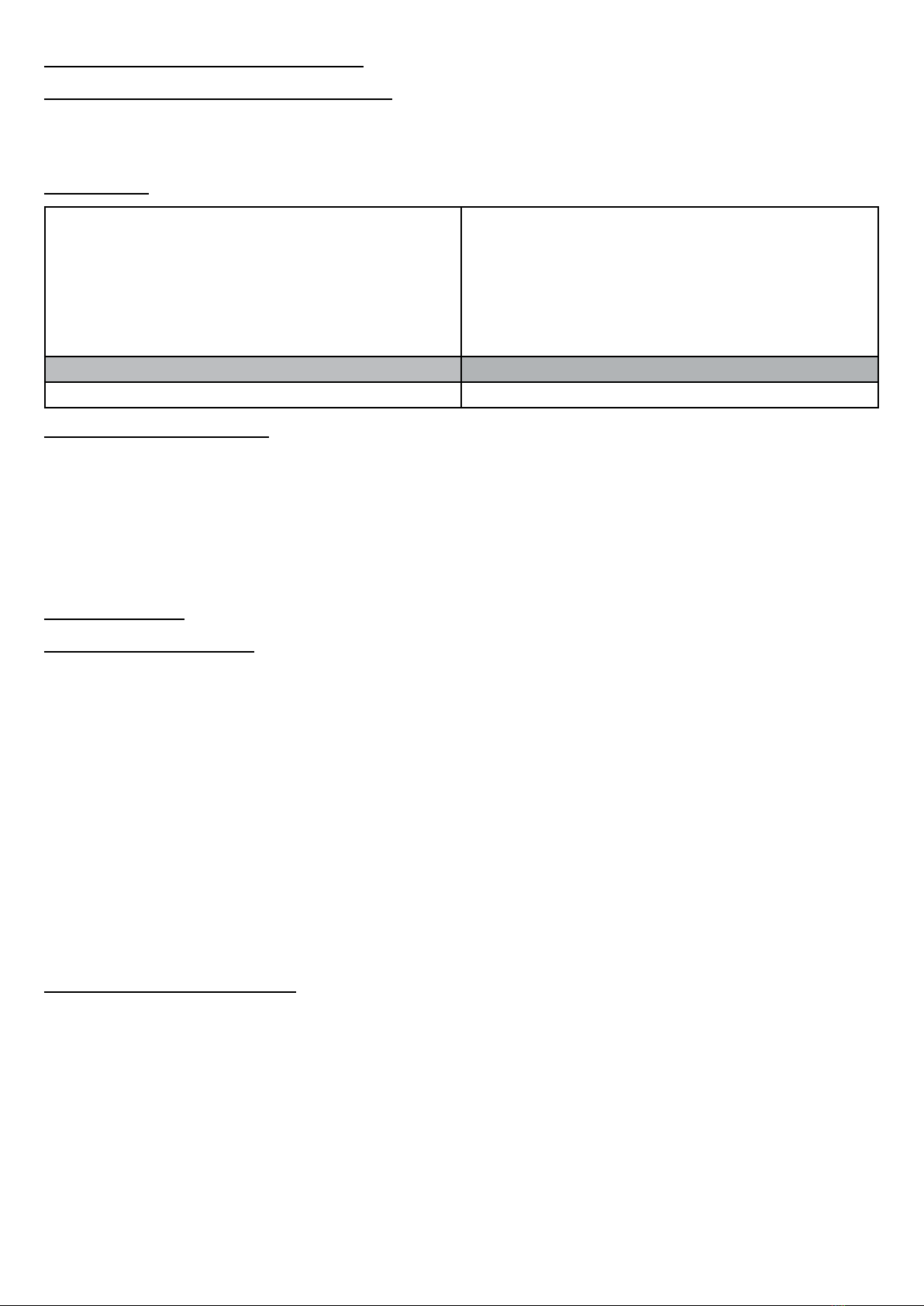
5.1 Error codes
Number of
ashes Malfuncon Possible causes Soluons
1User interface is
defecve • The user interface resets itself
constantly • Check the electrical connecons inside
the user interface housing.
• Replace the motor - interface assembly
if necessary.
2Network sub-
voltage • The network voltage has fallen
below 180VCA. • The interface will reset when the
voltage rises over 209VCA again for at
least 6 seconds
3Temperature • Motor temperature too high
(+100°C)
• Motor temperature too low
(-20°C)
• Wait unl normal temperature condions
return and restart the pump.
4 Surge acvaon • The surge protecon has been
acvated • Check the electrical supply.
• Restart the pump.
5Network
overvoltage • The voltage exceeds 269VCA • The interface will reset when the
voltage returns to a normal value.
6Motor sha jammed • Motor start-up impossible
• The motor has stopped • Break the pump circuit and check
that no debris is blocking the turbine
(remove the pre-lter screen).
• Check that there is no debris blocking
the rear fan.
7Automac
vericaon • At least one of the automac
tests failed on start-up or
during operaon
• Break the pump circuit then reconnect it
to reset it.
8 Motor fault • At least one of the phases is
disconnected • Check the electrical connecons inside
the user interface housing.
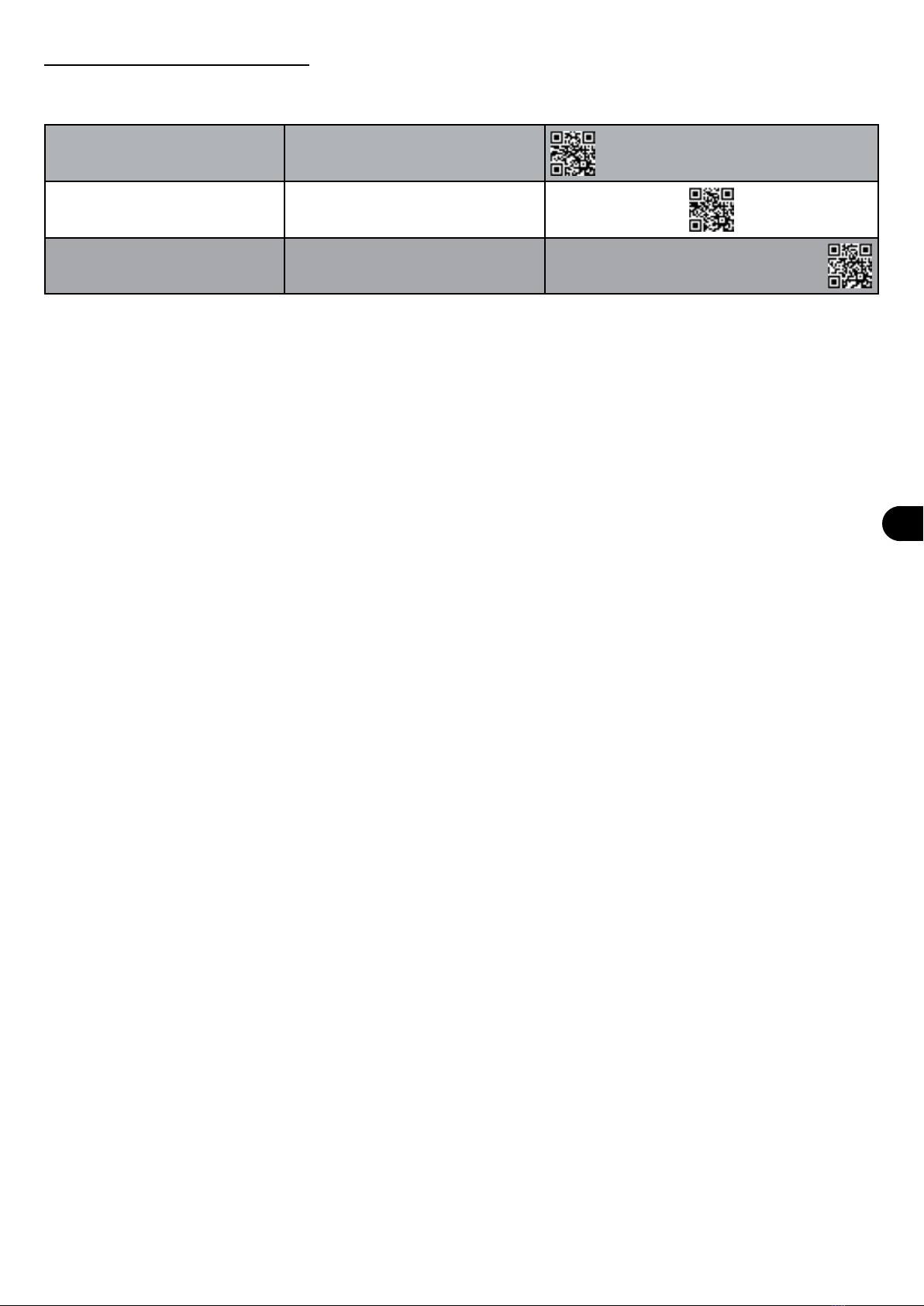
5.2 Equipment malfuncon
Malfuncon Possible causes Soluons
The water does not
circulate correctly • Pre-lter screen and/or lter
blocked with dirt
• Valves incorrectly set
• Clean the pre-lter screen and/or the lter
• Set the valves
Air bubbles are present
in the pre-lter screen • Air blocked in the circuit
• Swimming pool water level too
low
• Incorrect pre-lter cover seal
• Bleed the circuit
• Check the water level and top up if necessary
• Check that the cover and its seal are water-ght
There are air intakes • Couplings incorrectly ghtened
• Coupling seals incorrectly
posioned or damaged
• Reghten the couplings
• Change the seals
There is no air in the
circuit but the pressure
is low
• Debris jammed in the pump • Remove the debris by hand by opening the cover and
removing the pre-lter screen
• If debris remains, you must dismantle the pump to
access the turbine
• Cauon: these tasks must be carried out by a qualied
technician
There is no debris in the
pump but the pressure
is low
• The turbine and the pump
diuser are worn
• Electrical problem
• Seal worn
• Have the turbine and the diuser replaced by a
qualied technician
• Have the electrical installaon checked by a qualied
technician
• Replace the seal
There is a water leak
between the motor and
the pump body
• Mechanical lining damaged or
defecve • Replace the mechanical lining
• Cauon: these tasks must be carried out by a qualied
technician
The pump heats up and
switches o somemes • Poor air circulaon around the
motor
• Poor electrical connecons
• Current variaons too high
• Check that the motor is venlated enough to cool
down
• Check the electrical connecons
• Have the electrical network checked by a qualied
technician
The pump does not
start • No electrical supply to the pump
• The user interface cable is
damaged
• The "error" light ashes
• Check the electrical connecons
• Check the condion of the user interface cable
• See § “5.1 Error codes”
There is no damage to
the user interface • Cables damaged or poorly
connected in the user interface
housing
• Check the condion of the user interface cables