IN
S
TRUCTION
MANUAL
FOR
POS
T-
BED
IN
DUSTRIAL
S
EWING
MACH
I
NE
This manual is prepared to permit the sewing machine to be
used
efficiently and for highest performance.
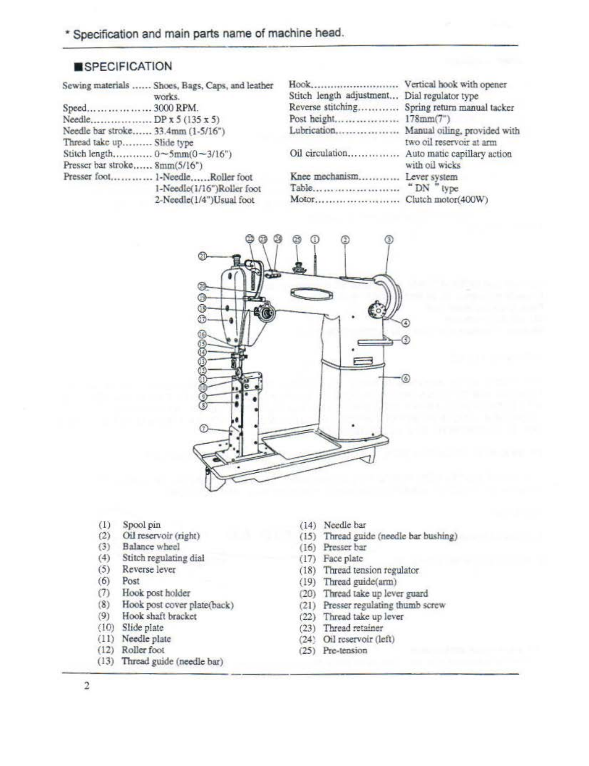
This machine is
post
-
bed
industrial sewing machine suitab
le
for sewing sboes,bags,capsandgeneral
leather works.
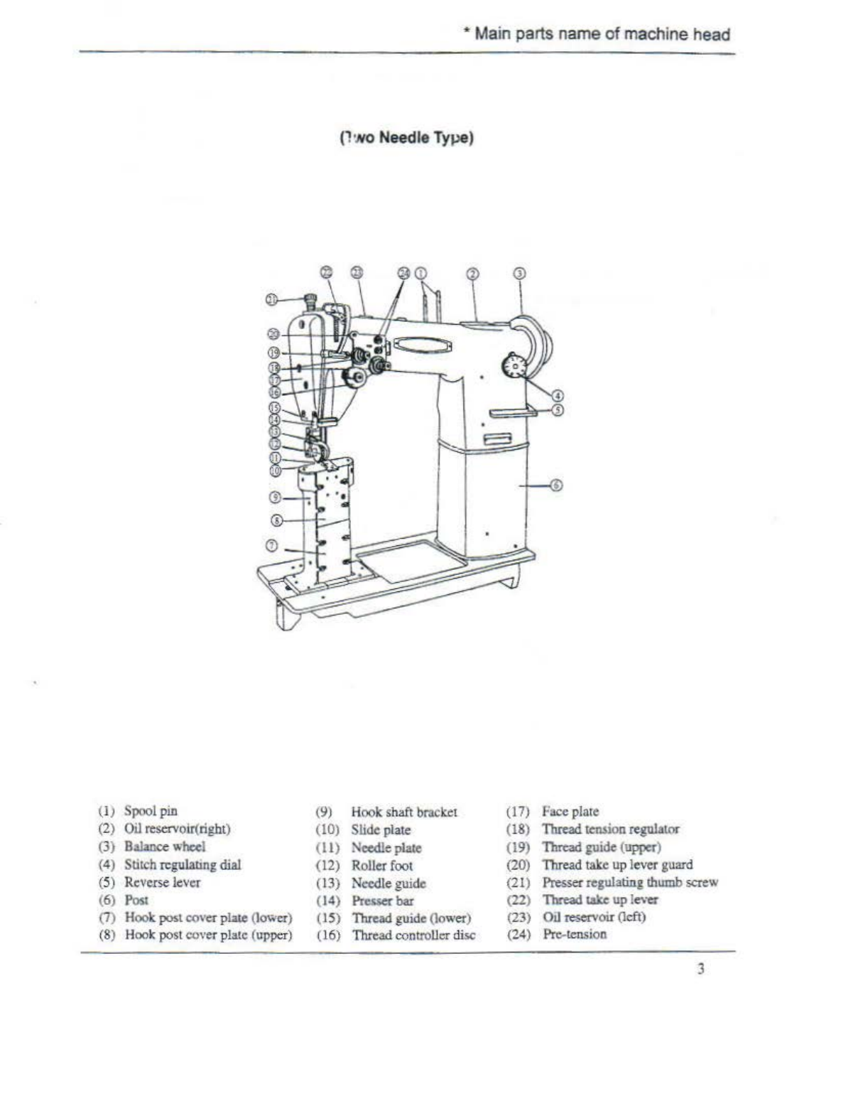
You
caneither select
1-n
.eedleor2-oeedle machine accordi
og
to your
type
of
works.
Being
eq
uipped withspring
return
reverse lever
rype
feed mechanism opener
type
vertical hook, and slide
type thread take-up provides perfect
uoif
omed
stitching.
- i
NDEX-
Specification
........
..
.........
.....
.................
.
.................................................................
.2
Main
parts
name
of
ma
c
hine
head
.................
.
..............................
..
...................
.
...........
3
L Preparation f
or
installation
of
machin
e
................
..
..........
.....
......
.
...............................
.4
1).
Place
of
installation
of
machine
..................
..
....................
.
........
,
...............................
4
2)
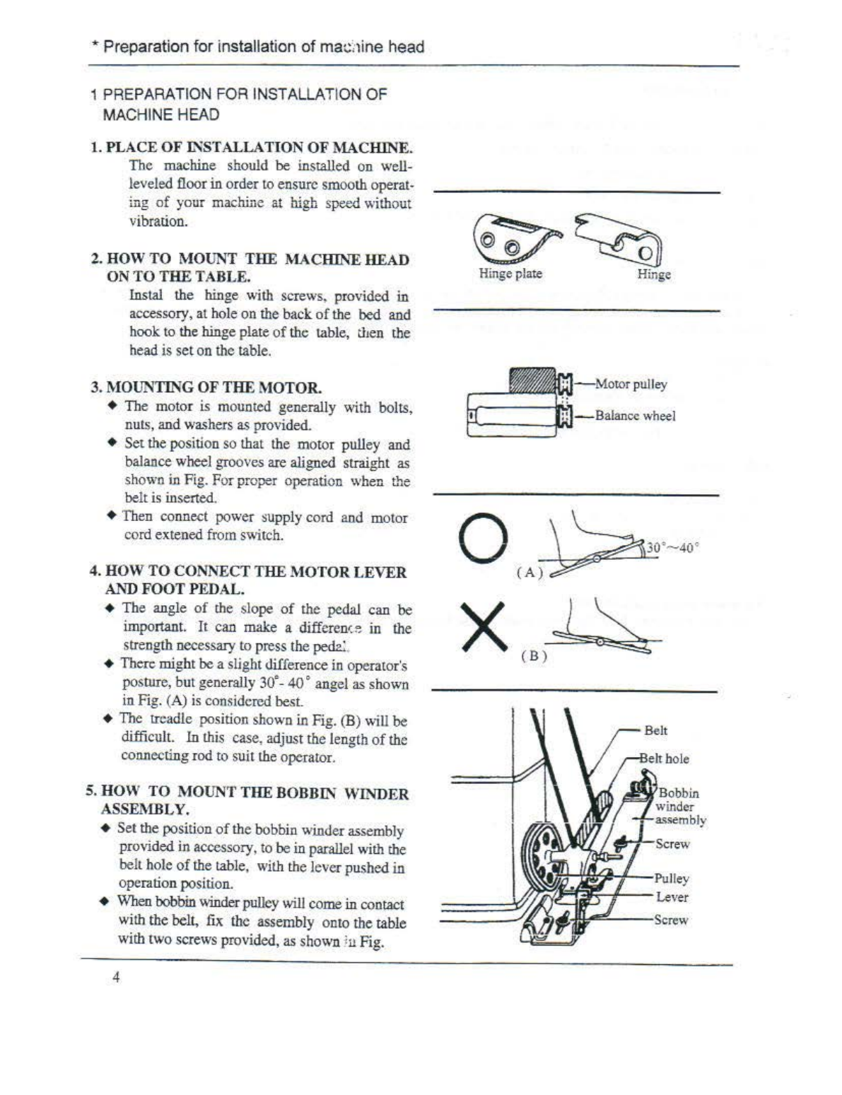
.How
to
mount the machine head
..
.
....•....
....
......
...
..
..
.......
..
...
,
......
.
.............
.
........
.
..
.
...
..
.4
3).
How
to
mount the motor..
.........
.
.........
..
..............
.
...........
.
...........
.......
.....................
.4
4). How
to
COillleet
the
motor
leverand
foot
pedal.••.•..•
.............•.
•••••.•.•.•.•.•..
.......•
••.•.•••••••...4
5). How to
moun
t the bobbin winder assembly
....
..
....
...
.....
...
....
.........
...
.......
..
............
..
....
.
.4
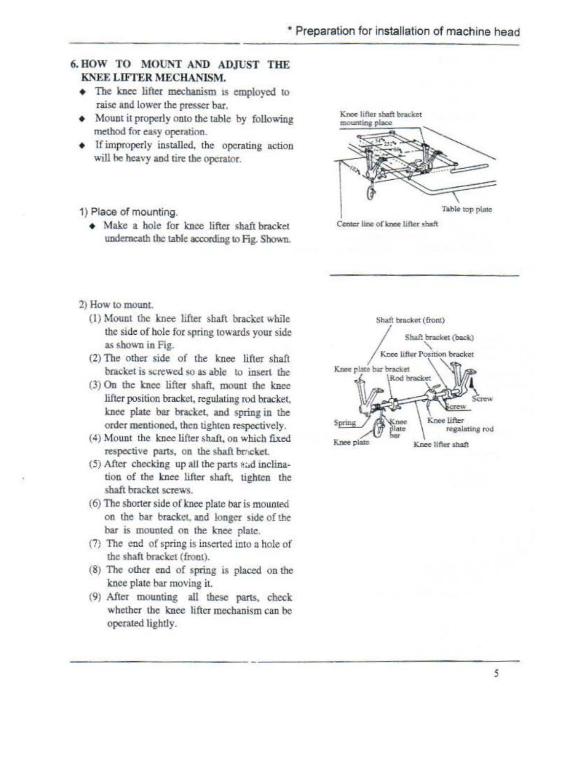
6).
!l
ow
to
mount
and
adjust
th
e knee lifter mechanism
..
.....
....
.........
...
..
.
...
....
.........
.....
...
......
.5
7).
How
to
mount
the
oil
pan.
..
...............................
.
..........
.
.....................
.
....•......
.
..........
6
8). How to mount the vibration
preventi.r.~
rubber
..
...
....
..
........
...
.........
..
.....
.
..
...
.......
..
..........
6
U.
Pr
eparation f
or
operation
..........................................................
.
...............................
7
I). Selection
of
thread
....
.
.........
...
.
..........
...
....
..
...
...
......
.........
....
........
....
.....
.
....
...
.....
7
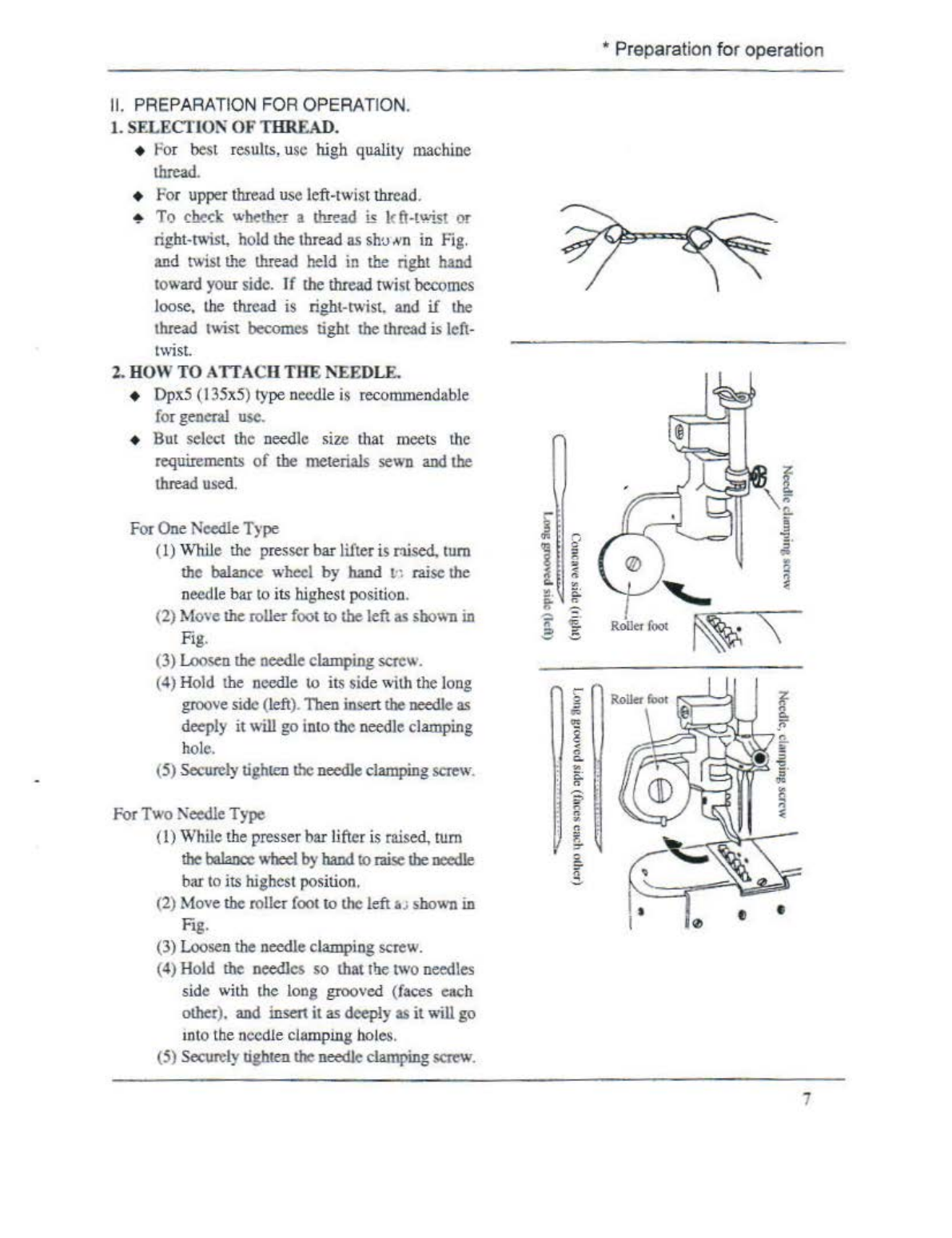
2). How
to
attach the
oc
:edle
............
......
...
.......
..
..
.....
.
.......
....
...
...
......
..
..
..................
.7
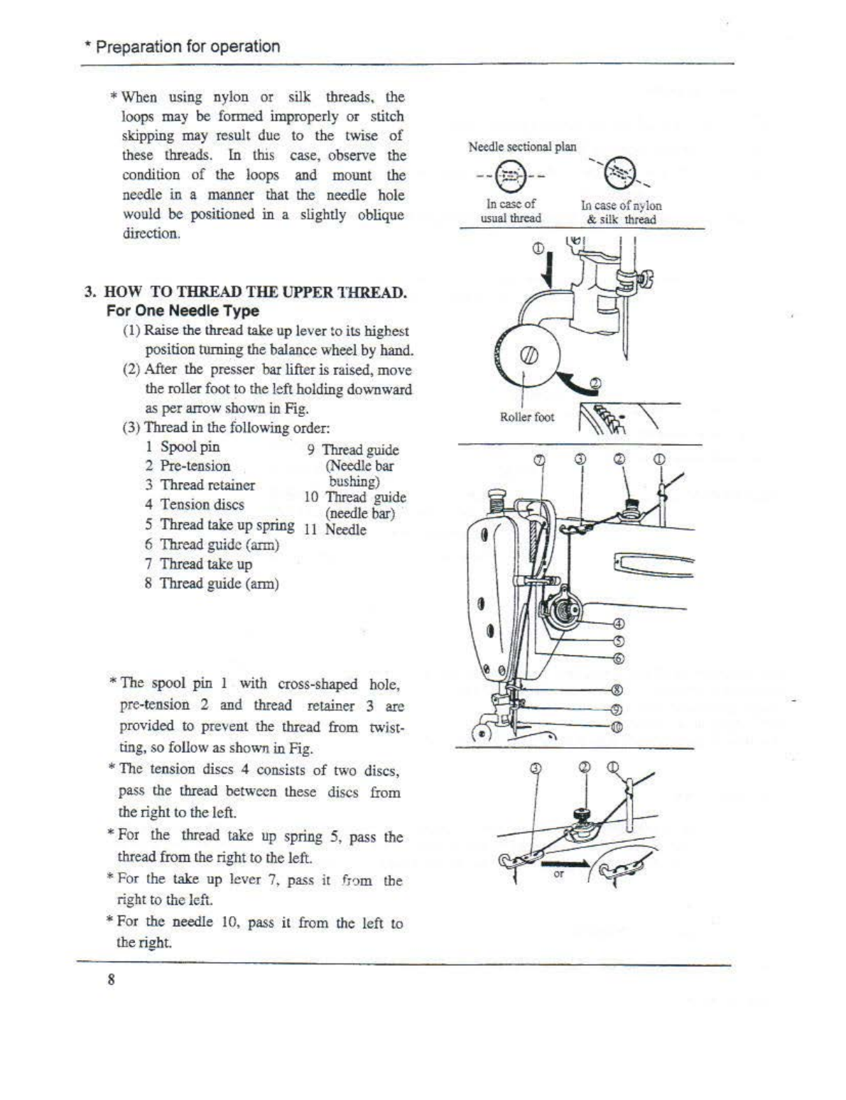
3
).
How
to
lead the upper thread
........
.
.....
.......
................
.......
.....
.....
...............
...
.........
8
4
).
How to wind
the
lower thread on the bobbin
..
.
......
.
................................
..
......
....
.
..
......
9
5).
How to adjust the bobbin winder asscmbly
...
..:
.........
....
............
.
.......
.
.......................
IO
6)
.
How
to place
the
bobbin into the hook
.....
...
...................
........
...............
.
...................
11
m.
Bow
to operate
.....
.......
...
....
......
.........
....
..
....
,
.......
...
..
.........
......
.......
.
......
..
..........
.
l3
1).
Starting
to
sewing
.................
...............
....
.......
.....
.....
........................................
13
2).
Sewing over
........
.
......
...
.........
...
................
.
......................
.........
..........
.
......
....
13
IV. Stitching adjustment
....
.....
...
......................
...............
........
............................
......
..
14
1
).
Adjustment
of
stitch length
.................
..
....................
..
...................
..
...........
..
......
14
2).
Forward and Reversestitching
....
.
...
........
....
.....
.......
.................
.....
.........
..
....
........
14
3).
Adjustment
of
thread !etlsion
...
...
........................................................................
!4
4). Adjustment
of{ccd
dog height and pressure of
pre.sse;-
on
materials
..............
.
..................
17
5). Propef ti
ming
between
th
e hook
and
needle.
......
...
..............
....
...
..
........
....
...
...
....
.
....
...
18
6). Proper timing between the book and opener
..........
.
...................................
..
.....
....
......
21
7). Proper timing between the
feed
dog
and
needle
...
....
..................................................
22
V.
Cleaning
and
Lubrication
.....................
...
.................
.
.............................................
23
1).
Oeaning
...........................
..
.................
.
................................................
..
........
23
2).
Lub
rication
...
....
...................
.....
.............
..
.....
.
.................................
,..,
.......
......
23
3).
Gr
ease
.
...............
.........
.....
..........
........
....
......
..................
...................
.....
....
....
24
From the library of: Superior Sewing Machine & Supply LLC