ZOJE ZJ1900DSS-3-04-V4-TP User manual


COMPUTER-CONTROLLED HIGH SPEED LOCKSTITCH BAR TACKING MACHINE
i
CONTENTS
I. EXPLANATION OF COMPUTER-CONTROLLED HIGH-SPEED LOCKSTITCH
BAR TACKING MACHINE
[1]SPECIFICATIONS..............................................................................................................................1
[2]CONFIGURSTION..............................................................................................................................2
1. Names of main unit................................................................................................................................2
[3]INSTALLATION..................................................................................................................................3
1. Attaching the connecting rod................................................................................................................3
2. Installing the head support rod..............................................................................................................3
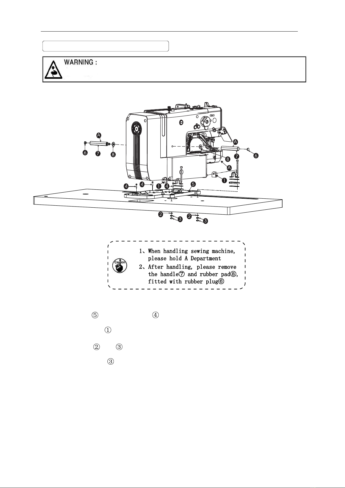
3. Installation of the sewing machine head..............................................................................................4
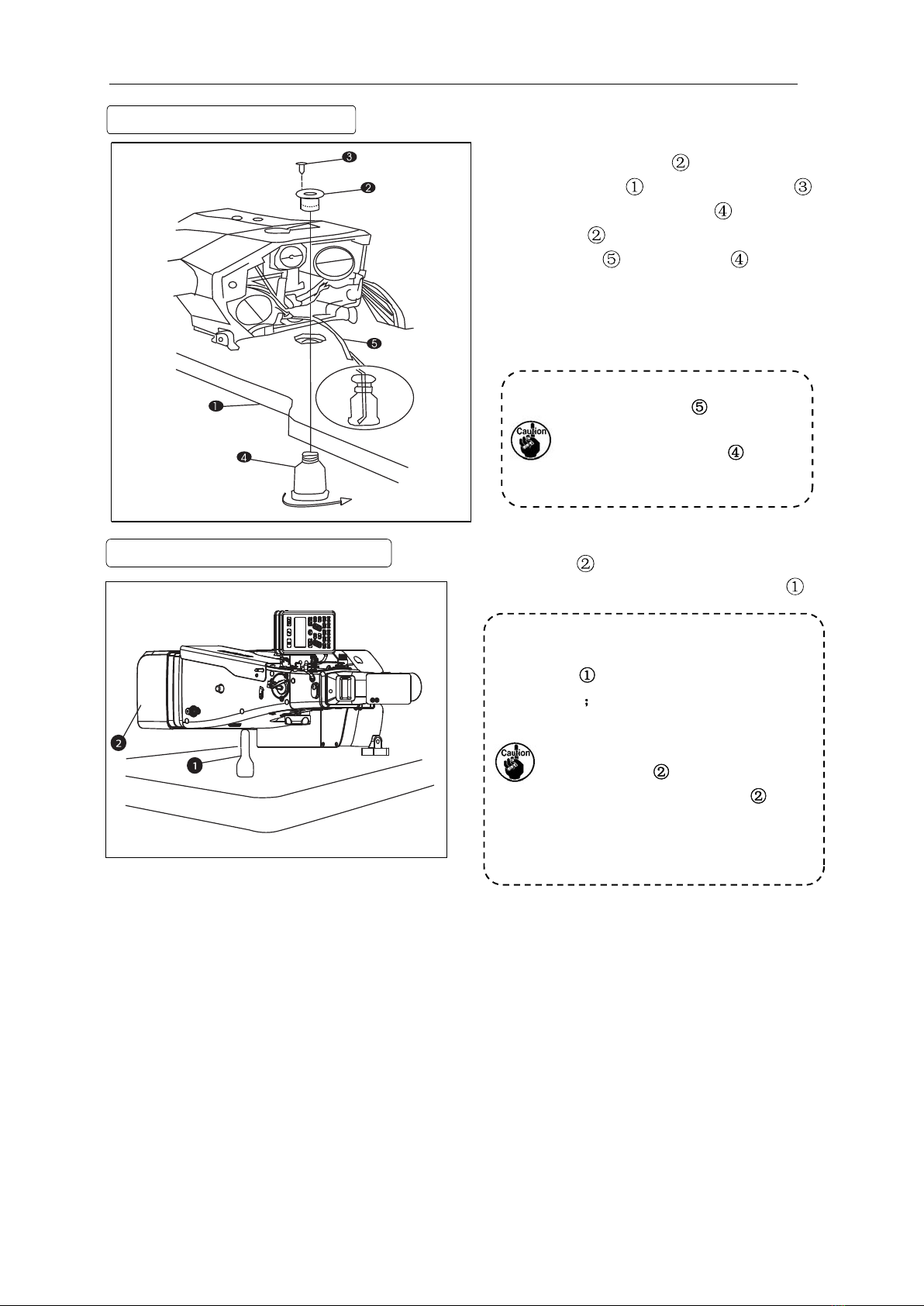
4. Installing the drain receiver...................................................................................................................5
5. Tilting the sewing machine head............................................................................................................5
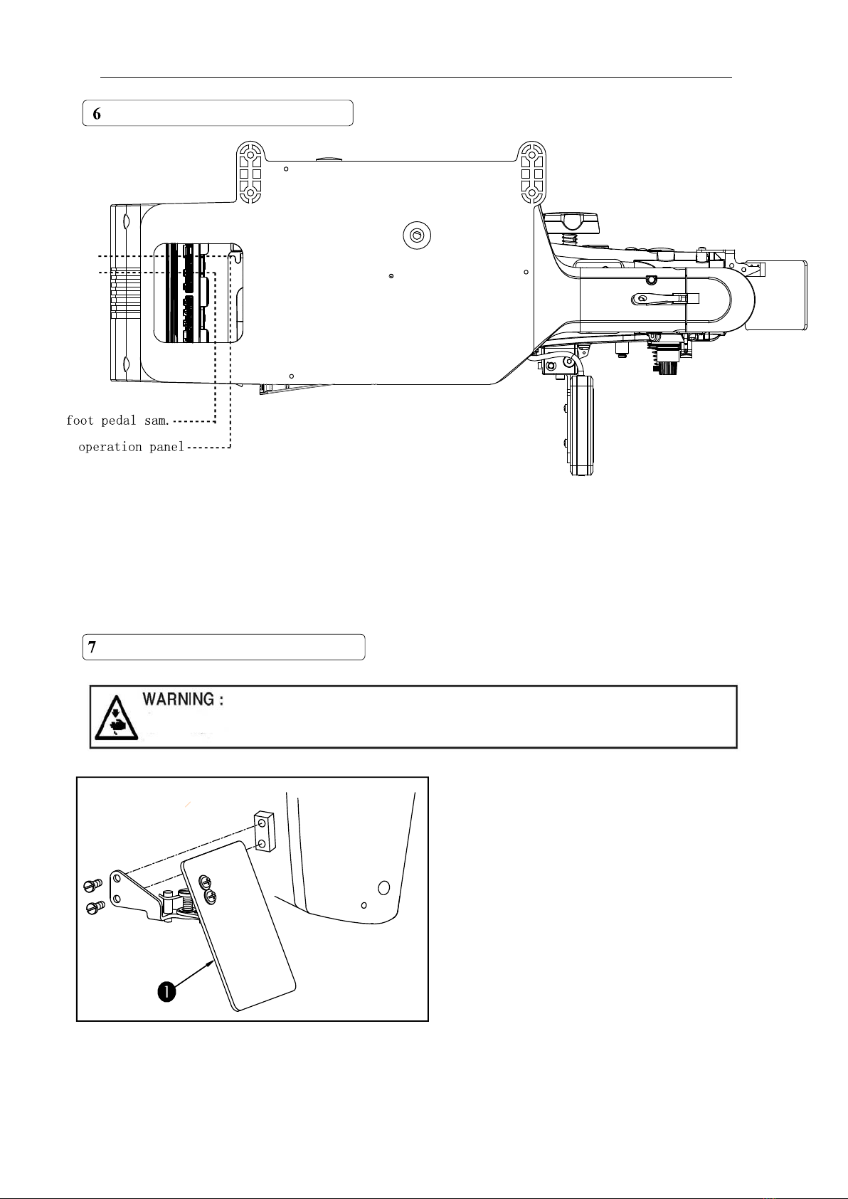
6.Connecting the operation panel..............................................................................................................6
7.Installing the eye protection cover..........................................................................................................6
8.Installing the thread stand.......................................................................................................................7
[4].OPERATION OF THE SEWING MACHINE...........................................................................7
1. Lubrication...............................................................................................................................................7
2. Attaching the needle................................................................................................................................8
3. Threading the machine head.................................................................................................................8
4. Installing and removing the bobbin case...............................................................................................9
5. Installing the bobbin................................................................................................................................9
6. Adjusting the thread tension..................................................................................................................10
7. Adjusting the thread take-up spring....................................................................................................10
[5]MAINTENANCE.................................................................................................................................11
1.Adjusting the height of the needle bar.......................................................................................11
2.Adjusting the needle-to-shuttle relation....................................................................................11
3.Adjusting the lift of the work clamp foot..................................................................................12
4.The moving knife and counter knife...........................................................................................13
5.Adjusting the wiper..........................................................................................................................14
6.Draining the waste oil......................................................................................................................14
7.Adjusting the amount of oil supplied to the hook...................................................................14
8.Replenishing the designed places with grease..........................................................................15
9.Adjusting the position of the shear driv pulley................................................................ 16
10.Position the wire- ing safety sensor and the wire- cam........................ 16
[6]Table of the standard patterns and standard clamp foot...............................................18
[7]Table of the optional parts ...........................................................................................................20
II.EXPLANATION OF COMPUTER-CONTROLLED HIGH-SPEED LOCKSTITCH
BUTTON SEWING MACHINE
[1] SPECIFICATIONS............................................................................................................................21

COMPUTER-CONTROLLED HIGH SPEED LOCKSTITCH BAR TACKING MACHINE
ii
[2]INSTALLATION OF THE SEWING MACHINE AND PREPARATION
OF THE OPERATION......................................................................................................................21
[3]NEEDLE AND THREAD..................................................................................................................21
[4]POSITION OF THE BUTTON CLAMP......................................................................................22
[5]ADJUSTING THE FEED PLATE..................................................................................................23
[6]ADJUSTING THE OPEN ANGLE OF THE BUTTON CLAMP JAW LEVER............23
[7]ADJUSTING THE LIFTING AMOUNT OF THE BUTTON CLAMP.............................24
[8]ADJUSTING THE PRESSURE OF THE WORK CLAMP FOOT.....................................24
[9]ADJUSTING THE WIPER SPING.................................................................................................25
[10]BUTTON SEWING SCOPE........................................................................................................25
III.TROUBLES AND CORRECTIVE MEASURES (SEWING CONDITIONS)....................26
IV.DRAWING OF THE TABLE..............................................................................................................29

COMPUTER-CONTROLLED HIGH SPEED LOCKSTITCH BAR TACKING MACHINE
- 1 -
.
1. Sewing area X lateral direction 40mm
Y longitudinal direction30mm
2. Max. Sewing speed 3200rpm
(when sewing pitches are less than 5mm in
X-direction and 3.5mm in Y-direction)
3. Stitch length 0.1-10mm (adjustable in 0.1mm step)
4. Feed motion of work clamp foot Intermittent feed (2-shaft drive by stepping motor)
5. Needle bar stroke 41.2mm
6. Needle DP×5 DP×17
7. Lift of work clamp foot 13mm (standard) Max.17mm
8. Shuttle standard semi-rotary hook oil wick lubrication
9. lubricating oil 10# (supplied by oiler)
10. Date recording EPROM
11. Enlarging/Reducing facility 20% to 200% (1% step) in X-direction
and Y-direction respectively
12. Enlarging/Reducing Patten enlargement/reduction can be done
by increasing/decreasing the stitch length
13. Max. Sewing speed limitation 400 to 3500rpm 100rpm
14. Pattern selection
15. Bobbin thread counter
16. Sewing machine motor
17. Dimensions
18. Weight
19. Power consumption
Specifying pattern No. type 1 to 00
UP/DOWN type 1-9999
550W Servo motor
W 1200mm L 540mm H 1100mm
Machine Kg
0. KW
20. Operating temperature range 5 to 35
21. Operating humidity range 35% to 85% No dew condensation
22. Line voltage Rated voltage ±10% 50-60Hz
EXPLANATION OF
1 SPECIFICATIONS

COMPUTER-CONTROLLED HIGH SPEED LOCKSTITCH BAR TACKING MACHINE
- 2 -
2 CONFIGURATION
1. Names of main unit
. Work clamp feet
. Machine head
. Thread stand
.
.
.
. Pedal switch
Power switch
Operation panel
Frame
1
2
5
6
4
7
7

COMPUTER-CONTROLLED HIGH SPEED LOCKSTITCH BAR TACKING MACHINE
- 3-
3 INSTALLATION
1.Attaching the connecting rod
FIX connecting rod to installing hole B
of pedal lever with nut . When
connecting rod is installed in installing
hole A, the depressing stroke go the pedal
is increased.
2.Installing the head support rod
Drive head support rod in hole
in the machine table.
1
2Secure the pedal with a wooden screw
in place.

COMPUTER-CONTROLLED HIGH SPEED LOCKSTITCH BAR TACKING MACHINE
- 4-
3. Installation of the swing machine head
(2).Fit hinge rubber to the hinge shaft, and fix the swing machine.
The flat pad , nut , followed by a fixed, pay attention
To prevent possible accidents caused by the full of the sewing machine,
p
erform the work b
y
two
p
ersons or more when the machine is
(3).
to the locking nut force, if twisted too tightly, then the shock result is
not satisfactory.
(1).The oil plate with wood screws fixed in the corresponding position of the platen.

COMPUTER-CONTROLLED HIGH SPEED LOCKSTITCH BAR TACKING MACHINE
- 5 -
4. Installing the drain receiver
Fix drain receiver in the installing
hole of table with four setscrews .
Screw in drain bin to drain
receiver . Insert sewing machine
drain pipe into drain bin .
Insert drain pipe until it will
go on further so that it does not
come off drain bin when
tilting the machine head
5. Tilting the sewing machine head turn head gently down , and leaning
the head on the head supporting bar at .
1. Before tilting the sewing machine
head, make sure that head support
rod is attached to the machine
table
2. When raising the sewing machine
head, do not raise it while holding
motor cover .It will be the cause
of breakage of motor cover .
3. Be sure to tilt the sewing machine
head on a flat place to prevent it
from falling.

COMPUTER-CONTROLLED HIGH SPEED LOCKSTITCH BAR TACKING MACHINE
- 6 -
. Installing the eye protection cover
The eye shield in the accessories
box should been installed in the
head on the left.
Be sure to attach this cover to protect the eyes from the disperse of needle
breakage.
Please let the operation panel line connect with the electronic control box according to
online identity, make sure the connection is correct.
Connecting the opera t ion panel
X7
X8

COMPUTER-CONTROLLED HIGH SPEED LOCKSTITCH BAR TACKING MACHINE
- 7 -
4OPERATION OF THE SEWING MACHINE
1. Lubrication
Check that the place between lower line Band
upper line A is filled with oil . Fill there with oil
using the oiler supplied with the machine as
accessories when oil is short.
*The oil tank which is filled with oil is only for
lubricating to the hook portion. It is possible to
reduce the oil amount when the number of
rotation used is low and the oil amount in the
hook portion is
(Refer to .
[ ]
1. DO not lubricate to the places other than the oil tank and the hook of Caution 2 below.
Trouble of components will be caused.
2. When using the sewing machine for the first time or after an extended period of disuse
use the machine after lubricating a small amount of oil to the hook portion.(Refer
to2.Adjusting the needle-to-shuttle relation of [7]MAINTENANCE
Turn of the power before starting the work so as to prevent accidents
caused by abrupt start of the sewing machine
8. Installing the thread stand
The line frame in the accessory
box should be installed in Table.

COMPUTER-CONTROLLED HIGH SPEED LOCKSTITCH BAR TACKING MACHINE
- 8 -
2. Attaching the needle
3. Threading the machine head
Pull out the thread by approximately 4cm from the needle after threading through the needle.
Install
Loosen setscrew and hold needle with
the long groove facing toward you. Then
fully insert it into the hole in the needle bar,
and tighten setscrew .
If the stitches are made as
shown in "A", attach the
needle facing to the direction
B" to a small extent.
Turn of the power before starting the work so as to prevent accidents
caused b
y
abru
p
t start of the sewin
g
machine
Turn of the power before starting the work so as to prevent accidents caused
by abrupt start of the sewing machine
1.When the silicon oil is used, thread through thread guide for silicon
2.For thick thread, pass the thread through one hole only of needle bar thread
guide

COMPUTER-CONTROLLED HIGH SPEED LOCKSTITCH BAR TACKING MACHINE
-- 9 --
5.Installing the bobbin
.Open hook cover
.Raise latch of bobbin case and
remove the bobbin case.
.When installing the bobbin case, fully
insert it into the shuttle shaft, and
close the latch.
Set the bobbin into bobbin case in the
direction shown in the figure.
Pass the thread through thread slit of
bobbin case and pull the thread as it is. By
so doing, the thread will pass under the tension
spring and be pulled out from thread hole .
Pass the thread through thread hole of
the horn section, and pull out the thread by
2.5cm from the thread hole.
Turn of the power before starting the work so as to prevent accidents
caused by abrupt start of the sewing machine.
Turn of the power before starting the work so as to prevent accidents
caused by abrupt start of the sewing machine
If it is not fully inserted, bobbin
case may slip off during sewing.
If the bobbin is installed in the bobbin case orienting the reverse direction, the
bobbin thread pulling out will result in an inconsistent state.
.Installing and removing the bobbin case

COMPUTER-CONTROLLED HIGH SPEED LOCKSTITCH BAR TACKING MACHINE
- 10 -
6. Adjusting the thread tension
7. Adjusting the thread take-up spring
If thread tension controller No.1 is turn
clockwise, the length of remaining thread on
the needle after thread trimming will be shorter.
If it turned counterclockwise, the length will be
longer.
Shorten the length to an extent that the thread is
not slipped off.
with to adjust the upper thread tension,
The standard stroke of thread take-up spring
is 8 to 10 mm, and the pressure at the start is
0.1 to 0.3N.
.Adjusting the stroke
Loosen setscrew and turn thread tension
asm. .Turning it clockwise will increase the
moving amount and the thread drawing amount
will increase.
.Adjusting the pressure
To change the pressure of the thread take-up
spring, insert a thin screwdriver into the slot of
thread tension post while screw is
tightened, and turn it. Turning it clockwise will
increase the pressure of the thread take-up
spring. Turning it counterclockwise will
decrease the pressure.
with to adjust the bottom line tension.

COMPUTER-CONTROLLED HIGH SPEED LOCKSTITCH BAR TACKING MACHINE
- -
MAINTENANCE
1. Adjusting the height of the needle bar
Turn OFF the power before starting the work so as to prevent
accidents cause by abrupt start of the sewing machine.
F type only
Bring needle bar to the lowest position of its stroke. Loosen needle bar connection
screw and adjust so that upper marker line engraved on the needle bar aligns with the
bottom end of needle bar bushing, lower . For F type only, adjust the needle bar to the
position where it is lowered by 0.8 mm to 1 mm from the center of upper marker line
engraved on the needle bar.
After the adjustment, make sure that there is no uneven torque. When stitch
skipping occurs in accordance with the sewing conditions, adjust the height of the
needle bar so as to lower it by 0.5 to 1 mm from the needle bar engraved line .
2. Adjusting the needle-to-shuttle relation
Turn OFF the power before starting the work so as to prevent
accidents cause by abrupt start of the sewing machine.
.Turn the hand wheel by hand. When
needle bar has gone up, adjust so that
lower marker line engraved on the needle
bar aligns with the bottom end of the needle
bar bushing , lower.

COMPUTER-CONTROLLED HIGH SPEED LOCKSTITCH BAR TACKING MACHINE
- -
.Loosen setscrew in the driver.
Open inner hook pressers to the
right and left, and remove inner hook
presser .
At this time, be careful not to let
inner hook come off and fall.
.Adjust so that the blade point of inner
hook aligns with the center of needle ,
and that a clearance of 0 mm is provided
between the front end of the driver and the
needle as the front end face of driver
receives the needle to prevent the needle
from being bent. Then tighten setscrew of
.Loosen setscrew of the shuttle, and
adjust the longitudinal position of the
shuttle. To do this adjustment, turn shuttle
race adjusting shaft clockwise or
counterclockwise to provide a 0.05 to 0.1
mm clearance between needle and the
blade point of inner hook .
.After adjusting the longitudinal position
of the shuttle, further adjust to provide a
7.5 mm clearance between the needle and
the shuttle by adjusting the rotating
direction. Then tighten setscrew of the
shuttle.
Apply a small amount of oil to race section and oil wick , and use the
sewing machine after an extended period of disuse or cleaning the
periphery of hook portion.
10
10
9
3. Adjusting the lift of the work clamp foot

COMPUTER-CONTROLLED HIGH SPEED LOCKSTITCH BAR TACKING MACHINE
- 13 -
4.The moving knife and counter knife
(2) . Remove six set screws of the top
cover, and take off top cover.
(3). Apply L-shaped wrench to socket
bolt of clamp , and loosen the
socket bolt.
(4). Push down L-shaped wrench to
increase the lift of the work clamp foot, or
pull it up to decrease the lift.
(5). After the adjustment, securely tighten
socket bolt .
(6). If the right and left work clamp feet
are not leveled, loosen fixing screw
and adjust the position of the work clamp
foot lever support plate to level them.
At this time, be careful not to cause work clamp foot lever support plate to
interfere with feed bracket .
If the work clamp foot lever support plate interferes with the wiper, readjust the
height of the wiper using setscrew in the wiper installing base.
Turn OFF the power before starting the work so as to prevent accidents
cause by abrupt start of the sewing machine.
.Loosen adjusting screw so that a
clearance of 18.5 mm is provided between
the front end of the throat plate and the top
end of thread trimmer lever, small . To
adjust, move the moving knife in the
direction of arrow.
.Loosen setscrew so that a clearance of
0.5 mm is provided between needle hole
guide and counter knife . To adjust,
move the counter knife.
Turn OFF the power before starting the work so as to prevent accidents
cause by abrupt start of the sewing machine.
(1) With the machine in stop mode,
remove two set screws of the right
decorative panel ,then remove the
decorative panel along the K direction.

COMPUTER-CONTROLLED HIGH SPEED LOCKSTITCH BAR TACKING MACHINE
- -
Loosen screw to adjust so that a
clearance of1.5 mm or more is
provided between the wiper and the
needle.
At this time, the standard of the
distance between the wiper and the
needle is 23 to 25 mm. By adjusting
the distance wide, the work clamp
foot can prevent stepping on needle
thread when it comes down.
Especially when the thin needle is
used, adjust the distance wide to
such an extent of 23 mm.
The position of the needle is
when the sewing machine has
stopped after the sewing finished.
6.Draining waste oil
7.A mount of oil supplied to the hook
When polyethylene oiler
becomes filled with oil, remove
polyethylene oiler and drain
the oil.
1) Loosen setscrew and remove
setscrew .
2) When screwing in adjustment
screw , the
amount of oil of oil pipe, left can
be reduced.
3) After the adjustment, screw in
setscrew and fix it.
1. The state of standard delivery is the position where is lightly screwed in and returned
by 4 turns.
2. When reducing the amount of oil, do not screw in the screw at once. Observe the state for
approximately half a day at the position where is screwed in and returned by2turns. If
reducing is excessive, worn-out of the hook will result.
5. Adjusting the wipper

COMPUTER-CONTROLLED HIGH SPEED LOCKSTITCH BAR TACKING MACHINE
- -
8.Replenishing the designated places with grease
When the sewing machine has been used for a certain number of times of sewing, error
code No. E221 is displayed on the operation panel at the time of turning ON the power. This
display informs the operator of the time of replenishing the designated places with oil. Be sure
to replenish the places with the oil below. Then call the memory switch No. 245 and set it to
"0" with the RESET key. Even after the display of the error No. E221, when the RESET key is
pressed, the error is released, and the sewing machine can be continuously used. Afterwards,
however, the error No. E221 is displayed every time the power is turned ON.
In addition, when the sewing machine is used further for a certain period of time after the
display of error No. E220, the error No. E221 is displayed and the sewing machine fails to
operate since the error cannot be released even when the RESET key is pressed.
When the error No. E221 is displayed, be sure to replenish the designated places below
with oil. Then start up the memory switch and set No. 245 to "0" with the RESET key.
.Outflow the residual oil in gearbox
.Lubricate the upper gearbox
After replenishing the places with oil, the error No. E220 or No. E221 is displayed again
unless the memory switch No. 245 is changed to "0".
Turn OFF the power before starting the work so as to prevent accidents
cause by abrupt start of the sewing machine.
1) Tilt the machine, remove the screws
and seal .
2) put back sewing machine, outflow the
residual oil in the gearbox.
3) tilt the machine again, put back the seals
and screws , then put sewing
machine back to the position.
1)
2)
When through the oil window , you can not
find oil outlet obviously, or it is without oil outlet,
you should add the oil into the wheel gear box.
Turn off the machine, you can take down the
screw and the rubber washer ,when it is
without oil outlet, please add 100ml 10# white
oil; when it is not oil outlet obviously, please
add 50-70ml.Please install back and parts,
turn on the machine and check whether it is
happened to oil outlet or not.
1
2
3

COMPUTER-CONTROLLED HIGH SPEED LOCKSTITCH BAR TACKING MACHINE
- -
positioning groove Keep the left end of the pulley
aligned with the right end of the positioning
groove that in the shear-driving shaft Then
tighten the screw on the pulley.
reference
plane
a b c
a
b
c

COMPUTER-CONTROLLED HIGH SPEED LOCKSTITCH BAR TACKING MACHINE
- -
Rotate the lift motor shaft to turn the lift cam to the lowest point of contact with the lift roller,this
moment the sc ew is facing directly above
Positioning reference plane of the trimming safety sensor chip horizontally upwards,and placing the
trimming safety sensor chip in the trimming safety sensor, then locking the screw to
fix the trimming safety sensor.
When the foot pedal is pressed for the first time,presser foot is pressed down, and the trimming safety
sensor chip does not enter the trimming safety sensor. When the foot pedal is pressed for the second time,
the machine starts to sew ,and if there is an alarm that the machine is trimming abnormality ,Please
loosen the screw and adjust the position of the trimming sensor chip in the clockwise direction.
Table of contents
Other ZOJE Sewing Machine manuals