Zumtobel DIMLITE User manual

DIMLITE
product handbook

2DIMLITE Installation and commissioning manual 4.0 |01.2014 |en

english

2DIMLITE Installation and commissioning manual 4.0 |01.2014 |en

DIMLITE Installation and commissioning manual 4.0 |01.2014 |en 1
2DIMLITE Installation and commissioning manual 4.0 |01.2014 |en
english
CONTENTS
Contents
Safety instructions. . . . . . . . . . . . . . . . . . . . . . . . . . . . . . . . . . . . . . . . . . . . . . . . . . . . . . . . . . . . . . . . . . 2
Introduction . . . . . . . . . . . . . . . . . . . . . . . . . . . . . . . . . . . . . . . . . . . . . . . . . . . . . . . . . . . . . . . . . . . . . . . 3
DIMLITE overview � � � � � � � � � � � � � � � � � � � � � � � � � � � � � � � � � � � � � � � � � � � � � � � � � � � � � � � � � � � � � � � � � � � � 3
Basic functions � � � � � � � � � � � � � � � � � � � � � � � � � � � � � � � � � � � � � � � � � � � � � � � � � � � � � � � � � � � � � � � � � � � � � � 4
Description of functions. . . . . . . . . . . . . . . . . . . . . . . . . . . . . . . . . . . . . . . . . . . . . . . . . . . . . . . . . . . . . . 5
Dimming/lighting scene � � � � � � � � � � � � � � � � � � � � � � � � � � � � � � � � � � � � � � � � � � � � � � � � � � � � � � � � � � � � � � � � 5
Presence-linked control � � � � � � � � � � � � � � � � � � � � � � � � � � � � � � � � � � � � � � � � � � � � � � � � � � � � � � � � � � � � � � � � 5
Stairwell function� � � � � � � � � � � � � � � � � � � � � � � � � � � � � � � � � � � � � � � � � � � � � � � � � � � � � � � � � � � � � � � � � � � � � 7
Daylight-linked control � � � � � � � � � � � � � � � � � � � � � � � � � � � � � � � � � � � � � � � � � � � � � � � � � � � � � � � � � � � � � � � � � 8
Operation � � � � � � � � � � � � � � � � � � � � � � � � � � � � � � � � � � � � � � � � � � � � � � � � � � � � � � � � � � � � � � � � � � � � � � � � � � 9
Type of operating devices� � � � � � � � � � � � � � � � � � � � � � � � � � � � � � � � � � � � � � � � � � � � � � � � � � � � � � � � � � � � � � 11
Mains disconnection � � � � � � � � � � � � � � � � � � � � � � � � � � � � � � � � � � � � � � � � � � � � � � � � � � � � � � � � � � � � � � � � � 11
Project design . . . . . . . . . . . . . . . . . . . . . . . . . . . . . . . . . . . . . . . . . . . . . . . . . . . . . . . . . . . . . . . . . . . . 12
Planning luminaire groups � � � � � � � � � � � � � � � � � � � � � � � � � � � � � � � � � � � � � � � � � � � � � � � � � � � � � � � � � � � � � 12
Planning operation � � � � � � � � � � � � � � � � � � � � � � � � � � � � � � � � � � � � � � � � � � � � � � � � � � � � � � � � � � � � � � � � � � 13
Arranging presence detectors/motion sensors � � � � � � � � � � � � � � � � � � � � � � � � � � � � � � � � � � � � � � � � � � � � � � � 18
Planning the stairwell function � � � � � � � � � � � � � � � � � � � � � � � � � � � � � � � � � � � � � � � � � � � � � � � � � � � � � � � � � � 19
Planning daylight-linked control � � � � � � � � � � � � � � � � � � � � � � � � � � � � � � � � � � � � � � � � � � � � � � � � � � � � � � � � � 19
Installation . . . . . . . . . . . . . . . . . . . . . . . . . . . . . . . . . . . . . . . . . . . . . . . . . . . . . . . . . . . . . . . . . . . . . . . 20
Wiring diagram � � � � � � � � � � � � � � � � � � � � � � � � � � � � � � � � � � � � � � � � � � � � � � � � � � � � � � � � � � � � � � � � � � � � � 21
Housing label � � � � � � � � � � � � � � � � � � � � � � � � � � � � � � � � � � � � � � � � � � � � � � � � � � � � � � � � � � � � � � � � � � � � � � 23
Commissioning � � � � � � � � � � � � � � � � � � � � � � � � � � � � � � � � � � � � � � � � � � � � � � � � � � � � � � � � � � � � � � � � � � � � � 24
Test key/Status LED� � � � � � � � � � � � � � � � � � � � � � � � � � � � � � � � � � � � � � � � � � � � � � � � � � � � � � � � � � � � � � � � � � 24
Carrying out an installation test � � � � � � � � � � � � � � � � � � � � � � � � � � � � � � � � � � � � � � � � � � � � � � � � � � � � � � � � � 26
Interruptions to the voltage supply at the DIMLITE control device� � � � � � � � � � � � � � � � � � � � � � � � � � � � � � � � � � 27
Configuration . . . . . . . . . . . . . . . . . . . . . . . . . . . . . . . . . . . . . . . . . . . . . . . . . . . . . . . . . . . . . . . . . . . . . 28
Setting the type of operating device � � � � � � � � � � � � � � � � � � � � � � � � � � � � � � � � � � � � � � � � � � � � � � � � � � � � � � 28
Setting/saving/changing lighting scenes � � � � � � � � � � � � � � � � � � � � � � � � � � � � � � � � � � � � � � � � � � � � � � � � � � � 29
Assigning an IRTOUCH remote control� � � � � � � � � � � � � � � � � � � � � � � � � � � � � � � � � � � � � � � � � � � � � � � � � � � � � 30
Configure presence-linked control � � � � � � � � � � � � � � � � � � � � � � � � � � � � � � � � � � � � � � � � � � � � � � � � � � � � � � � 31
Configuring stairwell function � � � � � � � � � � � � � � � � � � � � � � � � � � � � � � � � � � � � � � � � � � � � � � � � � � � � � � � � � � � 33
Configuring daylight-linked control � � � � � � � � � � � � � � � � � � � � � � � � � � � � � � � � � � � � � � � � � � � � � � � � � � � � � � � 33
Setting the fade time � � � � � � � � � � � � � � � � � � � � � � � � � � � � � � � � � � � � � � � � � � � � � � � � � � � � � � � � � � � � � � � � � 35
Locking and releasing configuration options � � � � � � � � � � � � � � � � � � � � � � � � � � � � � � � � � � � � � � � � � � � � � � � � 36
Restoring factory settings� � � � � � � � � � � � � � � � � � � � � � � � � � � � � � � � � � � � � � � � � � � � � � � � � � � � � � � � � � � � � � 37
Removing/adding/replacing devices � � � � � � � � � � � � � � � � � � � � � � � � � � � � � � � � � � � � � � � � � � � � � � � � � � � � � � 38
Technical data . . . . . . . . . . . . . . . . . . . . . . . . . . . . . . . . . . . . . . . . . . . . . . . . . . . . . . . . . . . . . . . . . . . . 39
Appendix . . . . . . . . . . . . . . . . . . . . . . . . . . . . . . . . . . . . . . . . . . . . . . . . . . . . . . . . . . . . . . . . . . . . . . . . 41
Questions and answers � � � � � � � � � � � � � � � � � � � � � � � � � � � � � � � � � � � � � � � � � � � � � � � � � � � � � � � � � � � � � � � 41
Extract from minimum illuminance according to EN 12464 � � � � � � � � � � � � � � � � � � � � � � � � � � � � � � � � � � � � � � 43
Disposal � � � � � � � � � � � � � � � � � � � � � � � � � � � � � � � � � � � � � � � � � � � � � � � � � � � � � � � � � � � � � � � � � � � � � � � � � � 44
CE conformity � � � � � � � � � � � � � � � � � � � � � � � � � � � � � � � � � � � � � � � � � � � � � � � � � � � � � � � � � � � � � � � � � � � � � � 44
Glossary � � � � � � � � � � � � � � � � � � � � � � � � � � � � � � � � � � � � � � � � � � � � � � � � � � � � � � � � � � � � � � � � � � � � � � � � � � 44

2DIMLITE Installation and commissioning manual 4.0 |01.2014 |en
SAFETY INSTRUCTIONS
Safety instructions
The instructions in this chapter have been compiled
to ensure that operators and users of the Zumtobel
DIMLITE lighting control are able to detect potential
risks in good time and take the necessary preventative
measures�
The operator must ensure that all users fully under-
stand these instructions and adhere to them� This
device may be installed and configured only by suitably
qualified personnel�
Use of system
Proper use
Control of indoor lighting systems�
The device may only be used for this intended purpose�
Improper use
Outdoor use�
Extensions and modifications to the product�
Use of third-party components and accessories that
have not been specifically approved by Zumtobel�
Warning
Improper use could result in injury, malfunction or da-
mage to property� The operator must inform all users of
the potential risks associated with the use of the equip-
ment and about protective countermeasures�
Surroundings
Not to be used in corrosive or explosive surroundings�
Dangers associated with
the operation of the system
Danger of death from power.
Countermeasures
Disconnect the power to the entire lighting system be-
fore working on the lighting system�
Risk of damage caused by condensation.
Countermeasures
Prior to commissioning the system, wait until the control
device is at room temperature and completely dry�
Risk of damage from humidity.
Countermeasures
Only use the control device in dry rooms and protect it
against humidity�
Electromagnetic compatibility (EMC)
Although the Zumtobel control device meets the strin-
gent requirements of the appropriate directives and
standards on electromagnetic compatibility, it could
potentially interfere with other devices under certain
circumstances�

DIMLITE Installation and commissioning manual 4.0 |01.2014 |en 3
2DIMLITE Installation and commissioning manual 4.0 |01.2014 |en
english
INTRODUCTION
Introduction
DIMLITE is an ideal introduction to the world of intelligent lighting control� The basic model provides a number of
convenient features to which extra functions can easily be added using supplementary components� It's as easy
as putting together a jigsaw: just choose the pieces that are right for you�
DIMLITE overview
DIMLITE multifunction 2ch
• Two outputs for two separate luminaire groups
• One output for mains disconnection of operating devices (energy-saving operation)
• Two inputs for direct connection of conventional 230/240 V, 50/60 Hz momentary-action switches for individual
dimming of the two luminaire groups
• One input for direct connection of a conventional 230/240 V, 50/60 Hz momentary-action switch for recalling
lighting scenes
• One input for connecting a conventional presence detector for 230/240 V, 50/60 Hz
• A universal, digital interface for connecting up to 8 devices with digital interfaces (CIRCLE control unit, light
sensor, input device for conventional momentary-action switches, multi-sensor for registering the presence/
absence of people and infrared signals from remote controls)
• Presence-linked control designed to meet individual requirements with three operating modes and ten adjus-
table run-on times
DIMLITE multifunction 4ch
Differences to DIMLITE multifunction 2ch:
• Four outputs for four separate luminaire groups
• Four inputs for direct connection of conventional 230/240 V, 50/60 Hz momentary-action switches for indivi-
dual dimming of the four luminaire groups
• One input for connection of a conventional 230/240 V, 50/60 Hz momentary-action switch for simultaneous
dimming of all luminaire groups
• One input for direct connection of a conventional 230/240 V, 50/60 Hz momentary-action switch for recalling
lighting scenes
• One input for connecting a conventional presence detector for 230/240 V, 50/60 Hz
• A universal, digital interface for connecting up to 8 devices with digital interfaces (CIRCLE control unit, light
sensor, input device for conventional momentary-action switches, multi-sensor for registering the presence/
absence of people and infrared signals from remote controls)
• Presence-linked control designed to meet individual requirements with three operating modes and ten adjus-
table run-on times

4DIMLITE Installation and commissioning manual 4.0 |01.2014 |en4DIMLITE Installation and commissioning manual 4.0 |01.2014 |en
Basic functions
Outputs for luminaire groups
DALI or DSI operating devices can be connected to the outputs� It is not possible to operate DALI and DSI opera-
ting devices on the same output simultaneously�
Output (Rel.)
The relay contact is used for the mains disconnection of operating devices (energy-saving operation)�
Inputs on the control device (T↑, T↓)
A separate input (Tx) is provided for dimming each luminaire group�
One connection (T↑or T↓) is provided on each input for dimming up and down (holding down the momentary-
action switch)� This connection can optionally be used for single momentary-action switch control� If the lighting
is switched off manually, briefly pressing the momentary-action switch recalls the last value set for the luminaire
group in question� Multiple conventional 230/240 V, 50/60 Hz momentary-action switches can be connected to
the inputs in parallel�
Input on the control device (T all)
This input is intended for dimming all luminaire groups up or down simultaneously� If the lighting is switched
off manually, briefly pressing the key calls up the last value set for all luminaire groups� Multiple conventional
230/240 V, 50/60 Hz momentary-action switches can be connected to the input in parallel�
Input on the control device (Sc1)
This input is designed to recall lighting scene 1 or switch off the lighting� Multiple conventional 230/240 V,
50/60Hz momentary-action switches can be connected to the input in parallel�
Input on the control device (PD/T)
Multiple conventional 230/240 V, 50/60 Hz motion sensors can be connected to the input in parallel� The motion
sensors act on all outputs simultaneously�
Universal, digital interface (Contr.IN)
Up to 8 devices (ED-Cxx, ED-SxED, ED-SENS, ED-EYE, ED-IR) can be connected to the interface� In principle,
multiple devices of the same type may be connected� The only exception is the ED-EYE light sensor: it may only
be connected once�
Presence-linked control
The DIMLITE control device enables lighting to be controlled by the presence/absence of people� Presence detec-
tors/motion sensors are required in addition to the DIMLITE control device�
Stairwell function
The DIMLITE control device enables the lighting to be automatically switched off after a run-on time has expired�
A momentary-action switch is required in addition to the DIMLITE control device�
Daylight-linked control
The DIMLITE control device enables lighting to be controlled by the level of daylight entering the room� A light
sensor is required in addition to the DIMLITE control device� Each output can be controlled individually�
INTRODUCTION

DIMLITE Installation and commissioning manual 4.0 |01.2014 |en 5
DESCRIPTION OF FUNCTIONS
4DIMLITE Installation and commissioning manual 4.0 |01.2014 |en
english
4DIMLITE Installation and commissioning manual 4.0 |01.2014 |en
ON/OFF
only
OFF
no
funct.
ON/corr
ON/OFF
only
OFF
no
funct.
ON/corr
Mode ON/OFF (recall lighting scene and switch off lighting)
If a person enters the detection range of the presence detector, the most
recently activated lighting scene will be recalled� If no one is located in
the detection range, the lighting is switched off once the run-on time has
expired and the fade time (64 s) has passed�
If multiple presence detectors are used: The lighting is only switched off
once all presence detectors register that the area is empty, and the last
run-on time has expired and the fade time has passed�
Mode only OFF (switch off lighting)
A lighting scene is recalled manually� If no one is located in the detection
range of the presence detector, the lighting is switched off once the run-
on time has expired and the fade time (64 s) has passed�
If multiple presence detectors are used: The lighting is only switched off
once all presence detectors register that the area is empty, and the last
run-on time has expired and the fade time has passed�
Description of functions
Dimming/lighting scene
Dimming is the variable adjustment of the level of brightness provided by the lighting� The DIMLITE control device
enables the user to dim the lighting manually at any time� The luminaire groups can be dimmed individually or
jointly�
A lighting scene is a configurable brightness setting for a specific activity or task� A lighting scene can be recalled
manually (e�g� by pressing a momentary-action switch) or automatically (e�g� using presence-linked control)�
Two rotary selector switches (Mode, Run-On) can be used to set the switching behaviour and run-on time for the
DIMLITE control device�
Presence-linked control
The most expensive light is a light that is left on in unused rooms and working areas� The DIMLITE control device
enables lighting to operated in an energy-saving way by turning lights off when nobody is present�
A further advantage of presence-linked control is that the lighting is immediately switched on again as soon as
someone enters the detection range of the presence detector/motion sensor�
Mode
Mode

ON/OFF
only
OFF
no
funct.
ON/corr
0
15
20 10
530
1
45
0,5
60
Run-On
min
DESCRIPTION OF FUNCTIONS
6DIMLITE Installation and commissioning manual 4.0 |01.2014 |en
Note:
! If at least one ED-SENS multi-sensor is connected to the universal, digital Contr.IN interface, the
PD/T input is not active.
! All presence detectors/motion sensors connected to the PD/T input or the universal, digital Contr�IN interface use
the settings (Mode, Run-On) made on the DIMLITE control device�
! The presence detectors connected to the universal digital Contr�IN interface can be assigned to individual
luminaire groups (see the section "Assigning an ED-SENS multi-sensor to one or more luminaire groups",
page31)�
! If no ED-SENS multi-sensor is connected to the universal digital Contr�IN interface, and no motion sensor for
presence-linked control or no momentary-action switch for stairwell function is connected to the PD/T input, the
rotary selector switch mode must be set to "no funct�"
Mode
Run-On
Mode no funct.
Presence-linked control is not operational�
Run-on time for the modes ON/OFF, only OFF und ON/corr Available
settings: 0 min, 0�5 min, 1 min, 5 min, 10 min, 15 min, 20 min, 30 min,
45min and 60 min�
ON/OFF
only
OFF
no
funct.
ON/corr
Mode ON/corr (recall lighting scene and change to corridor
lighting scene)
A lighting scene is recalled when a person enters the detection range
of the presence detector� If no one is located in the detection range, a
corridor lighting scene is recalled once the run-on time has expired� The
brightness for the corridor lighting scene is fixed at 10% (for all luminaire
groups)�
If multiple presence detectors are used: The corridor lighting scene is only
recalled once all presence detectors register that the area is empty, and
the last run-on time has expired and the fade time has passed�
Mode

DIMLITE Installation and commissioning manual 4.0 |01.2014 |en 7
DESCRIPTION OF FUNCTIONS
6DIMLITE Installation and commissioning manual 4.0 |01.2014 |en
english
ON/OFF
only
OFF
no
funct.
ON/corr
ON/OFF
only
OFF
no
funct.
ON/corr
Mode
Mode
Mode ON/OFF (switch on lighting and delay switch-off of lighting)
Briefly pressing the momentary-action switch recalls the last active ligh-
ting scene� Once the run-on time has expired, the lighting switches off
with a fade time of 64 seconds� If the momentary-action switch is pressed
again before the run-on time has expired, the run-on time starts again�
Mode ON/corr (switch on lighting and delay change to corridor
lighting scene)
Briefly pressing the momentary-action switch recalls the last active ligh-
ting scene� Once the run-on time has expired the corridor lighting scene is
recalled� If the momentary-action switch is pressed again before the run-
on time has expired, the run-on time starts again�
Stairwell function
Note:
!If at least one ED-SENS multi-sensor is connected to the universal digital Contr�IN interface, the PD/T input is
not active�
! If no ED-SENS multi-sensor is connected to the universal digital Contr�IN interface, and no motion sensor for
presence-linked control or no momentary-action switch for stairwell function is connected to the PD/T input,
the rotary selector switch mode must be set to "no funct�"
0
15
20 10
530
1
45
0,5
60
0
15
20 10
530
1
45
0,5
60
The DIMLITE control device allows for optimal energy-saving operation of lighting, in that the lighting (e�g� in a
stairwell) is switched on by pressing a momentary-action switch and automatically switched off after a set
run-on time has expired� This stairwell function is implemented by momentary-action switches connected to the
PD/T input�
min
min
Run-On
Run-On
Mode no funct., Mode only OFF
Corridor function is disabled�

DESCRIPTION OF FUNCTIONS
8DIMLITE Installation and commissioning manual 4.0 |01.2014 |en
Daylight-linked control
Optimal lighting conditions promote a feeling of wellbeing and boost motivation� And the best light of all is natural
daylight� However, if daylight is not available in sufficient quantity or quality, it is necessary to supplement it with
artificial light� Throughout the day, the DIMLITE control device automatically balances the level of artificial light in
a room against the amount of daylight�
Example of daylight-linked control
Day
Twilight
Minimum illuminance
Daylight Artificial light
Minimum illuminance
Daylight Artificial light
If a large amount of daylight is en-
tering the room, the first luminaire
group (Grp1) next to the window is
dimmed down� The luminaires in
the luminaire groups (Grp1, Grp2,
Grp3) are dimmed up to provide the
required minimum illuminance�
If the level of daylight in the room
falls, the luminaires in the other
groups (Grp2, Grp3) are dimmed up
accordingly to provide the required
minimum illuminance�
Note:
! All luminaire groups are designed for daylight-linked control�
! For information on project design, see the section "Planning daylight-linked control", page 19�
! For information on configuration, see the section "Configuring daylight-linked control", page 33"�

DIMLITE Installation and commissioning manual 4.0 |01.2014 |en 9
DESCRIPTION OF FUNCTIONS
8DIMLITE Installation and commissioning manual 4.0 |01.2014 |en
english
Remote control (IRTOUCH)
On/off key:
The on/off key is used to recall the last active lighting scene or switch off
the lighting�
Scene keys:
The scene keys are used to recall lighting scenes�
Scene key 1 recalls lighting scene 1, scene key 2 recalls lighting scene
2 and scene key 3 recalls lighting scene 3� The scene keys are also used
to save the lighting scene settings and the day and twilight points for
daylight-linked control�
Preset key:
The preset keys are used to select a luminaire group which is then
dimmed using the dimming rocker key or switched on/off using the on/off
key� The preset keys A-D correspond to luminaire groups Grp1–Grp4�
Dimming rocker key:
The dimming rocker keys are used to dim the luminaires� If a luminaire group has not been selected with the
preset keys A-D, all luminaires are dimmed simultaneously� If a luminaire group has been selected, only the lumi-
naires in this group are dimmed�
Operation
E
On/off key
Dimming
rocker key
Preset keys Dimming rocker keys
CIRCLE control unit (ED-Cxx)
On/off key:
The on/off key is used to recall the last active lighting scene� If the lighting
is switched off, the ring of light around the on-off key turns red to enable
the control unit to be found in the dark�
Scene keys:
The scene keys are used to recall lighting scenes� Scene key 1 recalls
lighting scene 1 (daylight-linked control, if required), scene key 2 recalls
lighting scene 2 and scene key 3 recalls lighting scene 3� The active
lighting scene is identified by an illuminated green circle section next to
the relevant scene key� The scene keys are also used to save the lighting
scene settings and the day and twilight points for daylight-linked control�
Dimming rocker keys:
The dimming rocker keys are used to manually dim the luminaires from luminaire group 1 or 2� Briefly pressing
the upper area of the dimming rocker key recalls the last value set for the luminaire group in question� Briefly
pressing the lower area of the dimming rocker key switches off the lighting for the luminaire group in question�
Holding a finger down on the upper or lower area of the dimming rocker key dims the associated luminaire group
between 1% and 100%�
On/off key
Scene keys Dimming rocker keys

DESCRIPTION OF FUNCTIONS
10 DIMLITE Installation and commissioning manual 4.0 |01.2014 |en
Conventional momentary-action switches
Momentary-action switches can be connected directly to the inputs on the DIMLITE control device and on the
ED-SxED input device connected to the control device at input Contr�IN�
Connected directly to the DIMLITE control device:
Lighting scenes are called up and the lighting is switched off using
conventional 230/240 V, 50/60 Hz momentary-action switches (short
press)� Luminaire groups can also be dimmed (long press)� If the lighting
has been switched off manually, a short press calls up the last value set
for the luminaire group in question�
Inputs T1, T2, T3, T4 and T all
Single momentary-action switch control:
Briefly pressing the momentary-action switch alternates between recalling the last value set for the luminaire
group in question and switching off the lighting� Holding down the momentary-action switch dims the associated
luminaire group up or down alternately between 1% and 100%�
Double momentary-action switch control:
Briefly pressing the momentary-action switch connected to Tx ↑ recalls the last value set for the luminaire
group in question� Briefly pressing the momentary-action switch connected to Tx ↓switches off the lighting for
the luminaire group in question� Holding down the appropriate momentary-action switch dims the associated
luminaire group between 1% and 100%�
Connected to ED-SxED
Rotary selector switch on ED-SxED set to 0:
Briefly pressing the momentary-action switch alternates between recalling the last value set for the luminaire
group in question and switching off the lighting� Holding down the momentary-action switch smoothly adjusts the
associated luminaire group up or down alternately between 1% and 100%�
Rotary selector switch on ED-SxED set to 1:
Lighting scenes 1-3 are recalled or the lighting is switched off�

DIMLITE Installation and commissioning manual 4.0 |01.2014 |en 11
DESCRIPTION OF FUNCTIONS
10 DIMLITE Installation and commissioning manual 4.0 |01.2014 |en
english
Daylight-linked control
Daylight linking can only be used to control the lighting when an ED-EYE light sensor is connected at input
Contr�IN�
Starting daylight-linked control
Daylight-linked control only starts when lighting scene 1 is recalled�
Lighting scene 1 can be directly recalled by pressing the keys on the ED-Cxx and IRTOUCH or by pressing
momentary-action switches on the ED-SxED and input Sc1� Lighting scene 1 can also be recalled by motion
sensors and momentary-action switches on input T all or PD/T if it was the last lighting scene active� If lighting
scene 1 was active before the lighting was switched off, lighting scene 1 is recalled when individual luminaire
groups are switched on and thus daylight-linked control is started for these luminaire groups�
If daylight-linked control has been stopped for a luminaire group by smooth adjustment, it is restarted when the
luminaire group is switched on or after 4 hours of non-operation�
Stopping daylight-linked control
Daylight-linked control is stopped by recalling lighting scene 2 or 3 or by switching off the lighting� If lighting
scene 1 is active and the luminaire groups are brightened or dimmed, daylight-linked control is only stopped for
these luminaire groups�
Note:
! The circle section illuminating green for the scene key on the CIRCLE control unit ED-Cxx indicates which
lighting scene is active�
Type of operating devices
The DIMLITE control device can be used to control DALI-compliant operating devices and DSI operating devices�
The type of operating device configured for the outputs can be preset or automatically detected and set by the
control device� All outputs Grp1 – Grp4 are set to control only DALI-compliant operating devices as standard��
Note:
! It is not possible to control DALI-compliant and DSI operating devices on the same output simultaneously�
However, it is possible to control DALI-compliant operating devices on one output (e�g� Grp1) and DSI operating
devices on a different output (e�g� Grp2)�
! If an operating device has both a DALI and DSI interface,, the outputs are automatically set to DALI-compliant
operating devices� However, this setting can be changed using the test key (see the section "Setting the type
of operating device", page 28)� The set type of operating device is retained even if the voltage supply is
interrupted�
Mains disconnection
This function helps to lower energy costs and increase energy efficiency� For this function to work, the phase for
the power supply of the operating devices must be passed through the relay contact (Rel�) If all connected lumi-
naires are switched off, the relay contact (Rel�) switches off power to the operating devices after 30 minutes�

PROJECT DESIGN
12 DIMLITE Installation and commissioning manual 4.0 |01.2014 |en
Note:
!DALI and DSI operating devices may not be connected to the same output simultaneously�
!A luminaire is allocated to a luminaire group by connecting the DALI/DSI control line to an output� Therefore
you must first determine which luminaires are to be located in which luminaire groups and plan the associ-
ated cabling�
!If you are planning daylight-linked control, you must take into account that each luminaire group will be
controlled individually� When planning the luminaire groups, consider the different directions in which day-
light enters the room see the section "Example of daylight-linked control", page 8� Plan the cabling
accordingly�
!If planning presence-linked control, take into account that, in principle, all luminaire groups will be controlled
together� However, separate luminaire groups can be controlled individually using the ED-SENS multi-sensor�
The IRTOUCH remote control is required for this configuration�
! If you are planning a mains disconnection (energy-saving mode), pass the phase for supplying power to
the operating devices through the relay contact (Rel�) In doing so, observe the maximum switching current
(max�16 A ohmic load) of the relay contact� If the maximum switching current is exceeded by the connected
operating devices, incorporate a sufficiently designed contactor�
!For details about cabling options (DALI/DSI control lines) and installation materials, see the section "DALI/DSI,
Contr�IN control lines", page 20�
Project design
Recommended procedure
1� Ascertain the customer's needs and requirements
2� Select a suitable control device (DIMLITE multifunction 2ch or DIMLITE multifunction 4ch)
3� Planning luminaire groups and mains disconnection
4� Plan the operation
5� Arrange presence detectors/motion sensors
6� Planning the stairwell function
7� Plan daylight-linked control
Planning luminaire groups
DIMLITE multifunction 2ch or DIMLITE multifunction 4ch:
The outputs are used to control two or four luminaire groups individually�
Luminaires within a luminaire group cannot be controlled individually�
Number of operating devices that can be connected:
Outputs Grp1 Grp2 Grp3 Grp4
DALI operating devices only 25 25 25 25
DSI operating devices only 50 50 50 50
DALI and DSI operating
devices
25 DALI or 25 DSI
operating devices
25 DALI or 25 DSI
operating devices
25 DALI or 25 DSI
operating devices
25 DALI or 25 DSI
operating devices

DIMLITE Installation and commissioning manual 4.0 |01.2014 |en 13
PROJECT DESIGN
12 DIMLITE Installation and commissioning manual 4.0 |01.2014 |en
english
Note:
! The ED-Cxx control unit is available in different models (different covers, colours, etc�)�
! The power for the ED-Cxx control unit is supplied via the Contr�IN control line�
! Up to 8 devices (ED-Cxx, ED-SxED, ED-SENS, ED-EYE, ED-IR) can be connected to the Contr�IN control line�
! The ED-Cxx control unit is installed in a single recessed European socket, DIN 0606 (ø 60 mm, depth 42 mm)
or a UK metal backbox (not included in supply)�
!The values associated with lighting scenes 1 to 3 are managed in the DIMLITE control device� Irrespective of
the control unit (ED-Cxx, ED-SxED, momentary-action switch connected to input Sc1) used to call up one of
the lighting scenes, the value that has been specified for the particular lighting scene is always activated�
!The two dimming rocker keys on CIRCLE control unit ED-Cxx cannot be allocated to luminaire groups 3 and 4�
Planning operation
A total of three lighting scenes can be set with the DIMLITE control device� They can be called up individually by
the relevant control units�
CIRCLE control unit (ED-Cxx)
CIRCLE control unit ED-Cxx is a wall-mounted control unit that can be used to call up three different lighting
scenes� It also includes two dimming rocker keys that can be used to dim luminaire groups 1 and 2 temporarily
while a lighting scene is active�
Contr
.IN (DA, DA)
DA DA
ED-Cxx
DA DA
ED-Cxx

PROJECT DESIGN
14 DIMLITE Installation and commissioning manual 4.0 |01.2014 |en
Input device ED-SxED
The ED-SxED input device has 4 separate inputs (T1–T4) to which conventional momentary-action switches can
be connected� The momentary-action switches are used to recall lighting scenes or dim luminaire groups�
The momentary-action switch inputs are configured as follows:
Rotary selector switch position 0:
5
6
0
14
2
3
8
7
9
Contr
.IN (DA, DA)
DA
DA
ED-SxED
Momentary-action
switch input
Effect
T1 Switch off all lighting
T2 Recall lighting scene 1
T3 Recall lighting scene 2
T4 Recall lighting scene 3
Momentary-action
switch input
Effect
T1 Luminaire group 1: Recall last set value; brighten
and dim lighting; switch off lighting
T2 Luminaire group 2: Recall last set value; brighten
and dim lighting; switch off lighting
T3 Luminaire group 3: Recall last set value; brighten
and dim lighting; switch off lighting
T4 Luminaire group 4: Recall last set value; brighten
and dim lighting; switch off lighting
Single momentary-action switch control
Rotary selector switch position 1:
5
6
0
14
2
3
8
7
9

DIMLITE Installation and commissioning manual 4.0 |01.2014 |en 15
PROJECT DESIGN
14 DIMLITE Installation and commissioning manual 4.0 |01.2014 |en
english
Note:
! Do not use momentary-action switches fitted with integrated glow lamps, RC elements or switching thyristors
because they are not recognised by the ED-SxED input device�
! The lines between the ED-SxED input device and the momentary-action switches must not exceed 30 cm�
! The voltage supply for the ED-SxED input device is provided via the Contr�IN control line�
! Up to 8 devices (ED-Cxx, ED-SxED, ED-SENS, ED-EYE, ED-IR) can be connected to the Contr�IN control line�
! The ED-SxED input device is installed in a single recessed European socket, DIN 0606 (ø 60 mm, depth
61 mm) or a UK metal backbox (not included in supply)�
Remote control (IRTOUCH)
The IRTOUCH remote control can be used to recall three lighting scenes or switch off the lighting� It also enables
up to 4 luminaire groups to be dimmed individually� The infrared signal is received by either the ED-SENS multi-
sensor or the ED-IR infrared receiver�
Contr
.IN (DA, DA)
DA DA
ED-SENS
IRTOUCH
DA DA
ED-IR
IRTOUCH
Note:
!The range of the IRTOUCH remote control depends on the conditions in the room: the infrared signal is
influenced by surfaces that are reflective (e�g� light walls, furnishings and floors) or absorbent (e�g� dark walls)�
!Devices that emit infrared light (such as laptops, PDAs or mobile phones with active infrared interfaces, as
well as plasma screens) can also influence the infrared signal emitted by the IRTOUCH remote control�
!Only one infrared emission code from the IRTOUCH remote control can be effective for each DIMLITE system�
If you u se more than one DIMLITE system, you can operate each system separately by assigning a dedicated
infrared emission code (up to a maximum of three different infrared emission codes can be allocated for each
ED-SENS multi-sensor or ER-IR infrared receiver)� To set the IRTOUCH infrared emission code, use the multi-
switch (0-2) in the battery compartment see the section "Assigning an IRTOUCH remote control", page 30 �

PROJECT DESIGN
16 DIMLITE Installation and commissioning manual 4.0 |01.2014 |en
L
Beispiel: Doppeltastersteuerung
T2
T1 T3 T4
Inputs T1, T2, T3, T4
L
Beispiel: Eintastersteuerung
T2
T1 T3 T4
Momentary-action switches on the DIMLITE control device
The DIMLITE control device has 2 or 4 inputs to which conventional momentary-action switches can be con-
nected� Briefly pressing the momentary-action switches connected to inputs T1 – T4 and T all recalls the last
value set for the luminaire groups in question or switches off the lighting� Holding down the momentary-action
switches dims or brightens the luminaire groups in question� A momentary-action switch connected to the
Sc1 input recalls lighting scene 1 or switches off the lighting� For a description of operating options, see the
section "Conventional momentary-action switches", page 10�
Example: single momentary-action switch
control
Example: double momentary-action switch
control
Example: single momentary-action switch control
Outputs Grp3 and Grp4 are not used.
Example: double momentary-action switch control
Outputs Grp3 and Grp4 are not used.
Contr.
IN
Rel.
L N
DA
DA
PIR
Sc1
Grp4
T4T3
Grp3Grp2Grp1
T2
T1
T all
Status Test
DIMLITE 4ch
Art.-Nr. 22 161 824
Ta: 0...50°C
230/240 V AC 50/60 Hz
LUXMATE
Lighting Management
L
Run-On
Mode
ON/OFF
only
OFF
no
funct.
ON/Corr
0
15
20
10
5
30
1
45
0,5
60
min
Contr.
IN
Rel.
L N
DA
DA
PIR
Sc1
L
Grp4
T4T3
Grp3Grp2Grp1
T2
T1
T all
Status Test
DIMLITE 4ch
Art.-Nr. 22 161 824
Ta: 0...50°C
230/240 V AC 50/60 Hz
LUXMATE
Lighting Management
Run-On
Mode
PIR ON/OFF
only
OFF
no
funct.
ON/Corr
0
15
20
10
5
30
1
45
0,5
60
min
Note:
! Any number of momentary-action switches can be connected to an input (T1, T2, T3, T4, T all, Sc1) in parallel�
!The phase (L) adjacent to the inputs must be the same as the phase used to supply power to the DIMLITE
control device�
!Loop-through wiring of the momentary-action switches to other DIMLITE control devices is not permitted�
Note:
! If an output is not used, the associated input (e�g� T3↓) must be electrically connected to another input
(e�g�T2↓) to which a momentary-action switch is connected� This connection method makes the switched-off
state of the unused outputs clear, which is necessary for mains disconnection, for example� In this case, the
relay contact (Rel�) only opens when all outputs are switched off�
Table of contents
Other Zumtobel Lighting Equipment manuals

Zumtobel
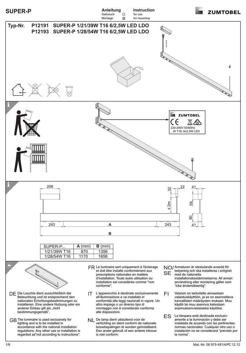
Zumtobel SUPER-P Series User manual

Zumtobel
Zumtobel EINGIESSGEH 344 ST Series User manual

Zumtobel
Zumtobel KXB Series User manual

Zumtobel
Zumtobel ONLITE central CPS K User manual

Zumtobel
Zumtobel SensControl User manual

Zumtobel
Zumtobel KXB S EVG ZONE2/22 BODY User manual

Zumtobel
Zumtobel KXA-2 Series User manual

Zumtobel
Zumtobel ONLITE central User manual

Zumtobel
Zumtobel LM-4UAS User manual

Zumtobel
Zumtobel ALVA User manual