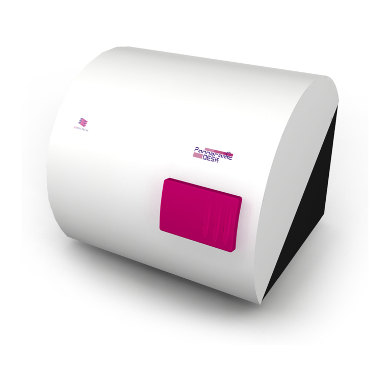
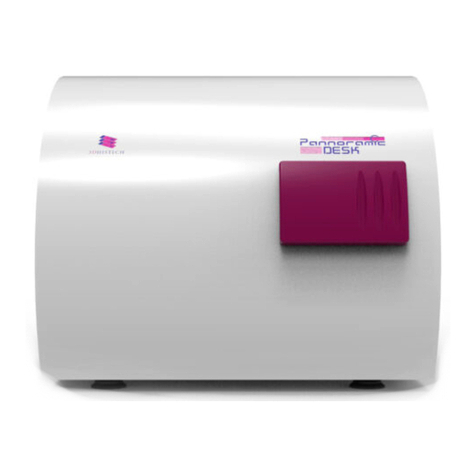
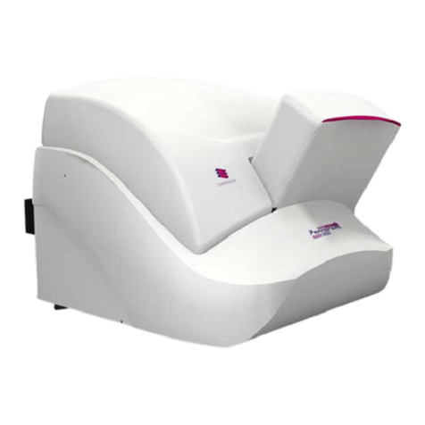
3D Histech Pannoramic 250 FLASH II User manual

Pannoramic 250 FLASH II
1.18.1
User’s Guide
May 29, 2014
Rev. 1

Pannoramic 250 FLASH II 1.18.1 User’s Guide
Contents
Disc aimer....................................................................................................................... 5
Character Formats and Symbo s....................................................................................... 7
Dec aration of Conformity............................................................................................... 8
Notes Regarding Operationa Safety................................................................................9
Notes on Warranty........................................................................................................ 11
Terms and Abbreviations...............................................................................................12
1 Product Description.................................................................................................... 13
1.1 Product Overview....................................................................................................................13
1.1.1 Intended Use..................................................................................................................................................13
1.1.2 Features and Bene its.....................................................................................................................................13
1.1.3 Warning and In ormation Labels....................................................................................................................15
1.1.4 Main parts o the Base Unit...........................................................................................................................16
1.2 System Overview......................................................................................................................17
1.2.1 Pannoramic 250 FLASH II system....................................................................................................................17
1.2.2 Hardware Options..........................................................................................................................................18
1.2.3 Control So tware............................................................................................................................................22
2 Insta ation................................................................................................................. 24
2.1 Control computer ports...........................................................................................................24
2.2 Connectors and cables.............................................................................................................25
2.3 Mounting the Lumencor Spectra unit......................................................................................26
3 Operating S ides and Magazines.................................................................................. 29
3.1 Preparing Slides and Magazines..............................................................................................29
3.2 A ixing Barcode Stickers to Slides...........................................................................................30
3.3 Inserting and Removing Slides.................................................................................................31
3.3.1 Insert slides into a magazine..........................................................................................................................31
3.3.2 Insert and remove magazines........................................................................................................................32
3.3.3 Opening/Closing the FL protective cover.......................................................................................................35
4 Software Description.................................................................................................. 36
4.1 Starting / Exiting the Pannoramic Scanner So tware...............................................................36
4.1.1 Starting the so tware......................................................................................................................................36
4.1.2 Exiting the so tware........................................................................................................................................37
4.2 Options.....................................................................................................................................37
4.2.1 Barcode Settings.............................................................................................................................................38
4.2.2 Image Compensation.....................................................................................................................................40
May 29 2014 – Rev. 1 3DHISTECH Ltd. 2(137)

Pannoramic 250 FLASH II 1.18.1 User’s Guide
4.2.3 Microscope Settings.......................................................................................................................................43
4.2.4 Event Call Settings..........................................................................................................................................48
4.3 Using Bright ield Manual Mode...............................................................................................50
4.3.1 Routine work panel........................................................................................................................................52
4.3.2 Scan Options window.....................................................................................................................................54
4.3.3 Preview panel.................................................................................................................................................57
4.3.4 Preview area scanned by preview camera.....................................................................................................60
4.3.5 Focus panel.....................................................................................................................................................66
4.3.6 Service panel..................................................................................................................................................68
4.3.7 Display ield and toolbar or live images........................................................................................................69
4.3.8 Start Scan........................................................................................................................................................71
4.4 Using Bright ield Automatic Mode..........................................................................................71
4.4.1 Routine work panel........................................................................................................................................71
4.4.2 Barcodes panel...............................................................................................................................................73
4.4.3 Preview panel.................................................................................................................................................77
4.4.4 Focus panel.....................................................................................................................................................78
4.4.5 Service panel..................................................................................................................................................79
4.4.6 Start Scan........................................................................................................................................................80
4.5 Using Fluorescent Manual Mode.............................................................................................81
4.5.1 Routine work panel........................................................................................................................................81
4.5.2 Scan Options...................................................................................................................................................86
4.5.3 Preview panel.................................................................................................................................................90
4.5.4 Hardware panel..............................................................................................................................................94
4.5.5 Service panel..................................................................................................................................................97
4.6 Using Fluorescent Automatic Mode........................................................................................98
4.6.1 Routine work panel........................................................................................................................................98
4.6.2 Barcodes panel.............................................................................................................................................103
4.6.3 Preview panel...............................................................................................................................................106
4.6.4 Focus panel...................................................................................................................................................107
4.6.5 Service panel................................................................................................................................................107
4.7 Scan To Server........................................................................................................................108
4.8 Using Pro iles.........................................................................................................................114
5 Troub eshooting and Maintenance............................................................................116
5.1 Sa ety In ormation.................................................................................................................116
5.1.1 Cleaning the device......................................................................................................................................117
5.1.2 Cleaning the magazine.................................................................................................................................117
5.1.3 Preventive maintenance...............................................................................................................................117
5.2 Troubleshooting.....................................................................................................................118
5.2.1 Fluorescent Applications (optional).............................................................................................................120
5.3 Maintenance..........................................................................................................................121
5.3.1 Opening the protective cover.......................................................................................................................121
5.3.2 Replacing uses o the main power switch...................................................................................................122
5.3.3 Replacing the HXP 120 Lamp Module ( or Fluorescent Option)..................................................................123
5.3.4 Removing a jammed or broken slide............................................................................................................125
May 29 2014 – Rev. 1 3DHISTECH Ltd. 3(137)
Pannoramic 250 FLASH II 1.18.1 User’s Guide
5.3.5 Installing and Removing the Filter Module (Fluorescent Option)................................................................127
5.3.6 Removing a Magazine rom the Transporting System..................................................................................128
5.3.7 Transporting.................................................................................................................................................130
6 Technica Data........................................................................................................... 132
Index........................................................................................................................... 136
May 29 2014 – Rev. 1 3DHISTECH Ltd. 4(137)

Pannoramic 250 FLASH II 1.18.1 User’s Guide
Disc aimer
Copyright © 2001-2014 3DHISTECH Ltd.
All rights reserved.
Intellectual property related to the 3DHISTECH products are as ollows:
EP 1,789,831; US 7,663,078; EP 2,024,772; JP 2009-512685; US 12/301,781; EP 1,644,767; JP 2007-
516451; US7,327,515; EP 1,994,398; JP 2008-557835; US 12/281,566; U0700210; US 6,246,785;
HU0900142; HU0700404; PCT/HU2007/000065; EP 08762668.5; US 12/663,537;
PCT/AT2006/000492; JP 2008-542552; EP 06817469; US 12/095,545; PCT/AT2006/000493; EP
06817470.5; US 12/095,596; HU0900741; US 61/264,732; US 11/826,752; P0401870;
PCT/IB2005/050344; US 11/662,976; HU0700409; US 12/042,050; US 77/636,144 and 007502032.
The above mentioned granted patents, granted utility model, registered trademarks, pending
international and national patent applications and the other corresponding IP are the sole properties
o the 3DHISTECH Ltd.
3DHISTECH Ltd. is not iab e for damage of whatever nature (inc uding, but not imited to, genera
or specific damage, indirect damage, consequentia damage or incidenta damage, inc uding the
resu ts of the ana ysis of the digitized s ides, for examp e, change of hea th status re ated to
erroneous diagnosis from the digitized s ide(s)) that stems from or is associated with use of
Product, digitized s ides, qua ity of staining, qua ity of stained s ides, qua ity of used method of
staining. 3DHISTECH Ltd. assumes no responsibi ity for the functiona ity and fau t-free condition of
your “app ication programs” (Workf ows, VBA macros, Commander scripts).
CAUTION
This product has not been approved or cleared as a medical device by the U.S. Food and Drug
Administration.
Do not use this device in close proximity to sources o strong electromagnetic radiation (e.g.
unshielded intentional RF sources), as these may inter ere with the proper operation.
Third-Party Disc aimer (LibTIFF – TIFF Library and Uti ities)
3DHISTECH Ltd. is not liable or damage o whatever nature (including, but not limited to, general or
speci ic damage, indirect damage, consequential damage or incidental damage, including damage
resulting rom lost pro its, interruption o business, loss o business in ormation, pecuniary loss or
similar damage) that stems rom or is associated with the incorporated part o this Product that is
made by Silicon Graphics Inc.
May 29 2014 – Rev. 1 3DHISTECH Ltd. 5(137)

Pannoramic 250 FLASH II 1.18.1 User’s Guide
THE SOFTWARE IS PROVIDED “AS IS” AND WITHOUT WARRANTY OF ANY KIND, EXPRESSED,
IMPLIED OR OTHERWISE, INCLUDING WITHOUT LIMITATION, ANY WARRANTY OF
MERCHANTABILITY OR FITNESS FOR A PARTICULAR PURPOSE.
IN NO EVENT SHALL SAM LEFFLER OR SILICON GRAPHICS BE LIABLE FOR ANY SPECIAL, INCIDENTAL,
INDIRECT OR CONSEQUENTIAL DAMAGES OF ANY KIND, OR FOR ANY DAMAGES WHATSOEVER
RESULTING FROM LOSS OF USE, DATA OR PROFITS, WHETHER OR NOT ADVISED OF THE POSSIBILITY
OF DAMAGE, AND ON ANY THEORY OF LIABILITY, ARISING OUT OF OR IN CONNECTION WITH THE
USE OR PERFORMANCE OF THIS SOFTWARE.
Further Information
For the latest in ormation on 3DHISTECH products and services, please visit our website at the
ollowing URL: http ://www.3dhistech.com.
Company Address: 29-33 Konkoly-Thege Miklos street, Building 6
1121 Budapest – HUNGARY
May 29 2014 – Rev. 1 3DHISTECH Ltd. 6(137)

Pannoramic 250 FLASH II 1.18.1 User’s Guide Character Formats and Symbols
Character Formats and Symbo s
Examp e Words or characters that appear on the screen. These include ield names, screen
and window titles, push-buttons and menu names, paths or options.
Keys on the keyboard. For example, unction keys (such as F11) or the Ctr +M key
combination.
Example Cross-re erences within this document or to other documents.
Warning! It might cause irreversible damage or harm to the user o the product or the
product itsel i this instruction is not ollowed.
Caution! It might cause the product not to work properly i this instruction is not ollowed.
Note: Calls attention to some important eatures.
May 29 2014 – Rev. 1 3DHISTECH Ltd. 7(137)

Pannoramic 250 FLASH II 1.18.1 User’s Guide Declaration of Conformity
Dec aration of Conformity
3DHISTECH Ltd. declares that the product Pannoramic 250 FLASH II slide scanner is designed and
produced with consideration o speci ied requirements according to the ISO 13485:2003 and IEC
61326-2-6:2005 standards, and con orms to the directives and other standards listed below:
IEC 61010-1:2001 (ed. 2), “Sa ety requirements or electrical equipment or measurement, control,
and laboratory use – Part 1: General requirements”
IEC 61010-2-101:2002 (ed. 1), “Sa ety requirements or electrical equipment or measurement,
control and laboratory use – Part 2-101: Particular requirements or in vitro diagnostic (IVD) medical
equipment”
EN 55011:1998, Group 1, Class A, “Limits and methods o measurement o radio disturbance
characteristics o industrial, scienti ic, and medical (ISM) radio- requency equipment”
This product has been tested to the requirements o CAN/CSA-C22.2 No. 61010-1, second
edition, including Amendment 1, or a later version o the same standard incorporating the same level
o testing requirements.
Con ormity with Directive 98/79/EC is marked by on the Pannoramic 250 FLASH II device.
Con ormity with Directive IEC 61010-2-101:2002 (ed. 1) is marked by on the product
labeling.
Further in ormation may be obtained rom the manu acturer:
3DHISTECH Ltd.
29-33 Konkoly-Thege Miklos street, Building 6
1121 Budapest – HUNGARY
May 29 2014 – Rev. 1 3DHISTECH Ltd. 8(137)

Pannoramic 250 FLASH II 1.18.1 User’s Guide Notes Regarding Operational Safety
Notes Regarding Operationa Safety
The below section o this User’s Guide contains in ormation and warnings o a kind that must be
ollowed by owner/operator personnel.
Warning and advisory symbols which are used on the base unit o the Pannoramic 250 FLASH II and in
the section 1.1.3 Warning and Information Labels have the ollowing meanings:
CAUTION
Disconnect mains plug be ore any kind o intervention into the device!
CAUTION
Crush hazard!
The Pannoramic 250 FLASH II, including any o its original accessory components, should not be
operated in any other way than described in section 1.1.1 Intended Use.
Any o the ollowing notes should be strictly observed:
Caution!
In the event o any non-con orming type o use, including non-con orming use
o assemblies or single parts, no liability will be assumed by the Manu acturer.
This shall also apply to service or repair work o any kind, which is per ormed by
other than duly authorized service personnel. All claims or warranty and
warranty services will be null and void in any such case.
Warning!
Insert the power cord plugs only into a grounding outlet. The protective action
must not be rendered ine ective by extension cables without protective
conductor. The Pannoramic 250 FLASH II has a built-in protection which must
not be rendered ine ective by extension cables without protective (earth-
ground) conductor.
Warning! The operation o the instrument in explosion-risk environments is not allowed.
Warning!
I protective devices are ound to be ine ective, the Pannoramic 250 FLASH II
must be shut down and precautions must be taken to prevent unintended
usage. For necessary repair work or work to restore proper operating condition,
you should contact the 3DHISTECH Customer Service.
Note:
Electric power to the Pannoramic 250 FLASH II is supplied via an internal mains
power supply unit. It allows or operation at line voltages in the range o 100 V
to 240 V ±10%, 50/60 Hz, without any extra acilities required or voltage
trans ormation.
Warning! Check that your local line voltage is compatible with Pannoramic 250 FLASH II
speci ications be ore you turn power on.
Disconnect p ug! Remember to unplug the power cord be ore you open the Pannoramic 250
FLASH II or replace a use!
May 29 2014 – Rev. 1 3DHISTECH Ltd. 9(137)

Pannoramic 250 FLASH II 1.18.1 User’s Guide Notes Regarding Operational Safety
Warning! Use only electric uses which are rated or the speci ied nominal current. You
are prohibited rom using makeshi t uses or short-circuiting o a use holder.
Warning!
The Pannoramic 250 FLASH II does not include any special acilities to protect
rom samples with an etching, potentially in ectious, toxic, radioactive or other
health-damaging e ect. You are under obligation to comply with all currently
binding legislation, notably, national accident prevention rules when handling
samples o this kind.
Caution!
Dirt or dust may adversely impact the operating capability o the Pannoramic
250 FLASH II. For this reason, measures must be taken to eliminate such
in luences to a maximum possible degree. During periods o non-use, the
Pannoramic 250 FLASH II must be protected with a dust cover. Check that power
is turned o be ore you put the cover on.
Crush hazard!
There is crush hazard in the movement area o the slide insert during operation.
Please note that the digitizing process has to be interrupted and the insert
moved via so tware to the output position be ore removing the insert.
Warning!
Clogged or covered ventilation slots may result in a heat build-up with a
damaging e ect or the Pannoramic 250 FLASH II. In extreme cases, this may
also cause ire. Keep the ventilation slots always unobstructed and re rain rom
inserting or dropping objects into a ventilation slot.
Warning! A de ective Pannoramic 250 FLASH II is not classi ied as domestic waste. It must
be properly disposed in accordance with currently valid legal requirements.
Warning!
The Pannoramic 250 FLASH II may not be operated by other than properly
instructed persons. Operating personnel must be ully aware o the potential
dangers which a particular ield o application involves. The Pannoramic 250
FLASH II is a precision instrument which may su er a signi icant reduction in
operational unctions or even physical destruction ollowing intervention
per ormed in any noncon orming manner.
Warning! I an HXP 120 illumination unit is used, the corresponding warnings included in
the manu acturer’s operating manual have to be observed.
May 29 2014 – Rev. 1 3DHISTECH Ltd. 10(137)

Pannoramic 250 FLASH II 1.18.1 User’s Guide Notes Regarding Operational Safety
Notes on Warranty
3DHISTECH Ltd. – as the Product Manu acturer – warrants the Pannoramic 250 FLASH II to be ree
rom aults in material and workmanship at the moment o installation. De ects must be noti ied
immediately on identi ication and maximum e orts must be undertaken in order to the amount o
damage as small as possible. On receiving notice o a ault, the Product Manu acturer will be under
obligation to remove the ault, at his own option, either by providing adequate repair services or by
delivering a aultless product or replacement. No warranty will be accepted in cases o natural wear
(notably, wear and tear parts) or improper product handling.
The Product Manu acturer will re use any liability in the event o damage resulting rom aulty
operation, negligence or unauthorized intervention into the product, notably, rom the replacement
o product parts or the usage o accessory parts rom other manu acturers. Any such case will void
the user’s claim or warranty.
Except or action which is explicitly described in this User’s Guide, you are prohibited rom
per orming any kind o maintenance or repair work at the Pannoramic 250 FLASH II. Only 3DHISTECH
Service personnel or speci ically authorized representatives are allowed to handle repair work. In
case o mal unction, contact the 3DHISTECH Service Support irst.
May 29 2014 – Rev. 1 3DHISTECH Ltd. 11(137)

Pannoramic 250 FLASH II 1.18.1 User’s Guide Notes Regarding Operational Safety
Terms and Abbreviations
CSV Comma Separated Value
FOV Field o View
NA Numerical Aperture
Photob eaching A phenomenon that leads to a dramatic loss o luorescence emission intensity
(a luorophore permanently loses the ability to luoresce) due to photon-induced
chemical damage and covalent modi ication, there ore luorescent signals cannot
be properly detected.
SWAP A ile that is used as a temporary location on the computer to store in ormation
that is not currently used by the RAM.
Virtua S ide / S ide A digital image o a thin glass plate on which specimens are mounted or
microscopic study:
a dynamic, interactive image that you can manage, save, magni y, zoom, name,
evaluate, annotate, mark and comment, send to a colleague electronically or co-
operation or advice, and so on.
May 29 2014 – Rev. 1 3DHISTECH Ltd. 12(137)

Pannoramic 250 FLASH II 1.18.1 User’s Guide 1 Product Description
1 Product Description
1.1 Product Overview
1.1.1 Intended Use
Pannoramic 250 FLASH II is designed to use transmitted light and re lected light luorescence to
digitize biological samples and specimens (typically histological sections). The target users o the
product can work or example, in education, research, industry or medical sectors.
Warning!
A ter each scanning make sure to inspect the digital slide or over-exposed
areas. I the slide is scanned based on improperly set parameters, it can
highly a ect the diagnostic result because o in ormation loss.
Warning!
Any modi ication to a hardware or so tware component o the PC will highly
a ect the unctionality o the scanner program.
1.1.2 Features and Benefits
The Pannoramic 250 FLASH II o ers world class bright ield and luorescent whole slide scanning on up
to 9 channels. An outstanding 0.19 µm/pixel (in Bright ield) and 0.16 µm/pixel (in Fluorescent)
resolution is achieved with a 40×/0.95 NA (equivalent to 52× magni ication in Bright ield and 62×
magni ication in Fluorescent modes) Carl Zeiss Plan-Apochromat objective.
The key eatures o the Pannoramic 250 FLASH II Scanner are as ollows:
•Extreme ast bright ield scanning mode:
•Continuously moving stage during scanning
•Bright ield camera with a rame rate o 130 ps
•Xenon lash lamp as light source
May 29 2014 – Rev. 1 3DHISTECH Ltd. 13(137)

Pannoramic 250 FLASH II 1.18.1 User’s Guide 1 Product Description
•Fluorescent scanning mode:
•High-end luorescent illumination device – Lumencor Spectra Light Engine 6
•3 times aster and more silent ilter change
•Multiband ilter support
•FL scanning with a low noise, 16-bit scienti ic CMOS pco.edge 4.2 camera
•So tware-aimed lat- ield correction compensation method to create homogenous
slide image
•Magazine stack cover to protect luorescent slides against photo bleaching
•Image quality:
•Image sharpening (both or Fluorescence and Bright ield) eature which improve the
visual appearance o digital slides
•Focus algorithm inds the ocus which is most appealing to the human eye
•Motorized camera changer or color camera or bright ield, and a cooled monochrome CCD
camera or a scienti ic CMOS camera or luorescence
•Motorized Objective changer or two objectives (Plan-Apochromat 0.8 NA or 0.95 NA)
•3MP camera or barcode reading and preview image
•Compact design:
•Cameras are placed inside the unit
•Built-in power supply
•250 slide automatic loading and scanning
This device is recommended or customers, who need high quality and high throughput granted by
the biggest loading capacity o 250 slides.
May 29 2014 – Rev. 1 3DHISTECH Ltd. 14(137)

Pannoramic 250 FLASH II 1.18.1 User’s Guide 1 Product Description
1.1.3 Warning and Information Labe s
The ollowing igure contains the labels used on the Pannoramic 250 FLASH II main unit and the HXP
120 luorescent illumination unit.
Figure 1 – Warning and information labels
May 29 2014 – Rev. 1 3DHISTECH Ltd. 15(137)

Pannoramic 250 FLASH II 1.18.1 User’s Guide 1 Product Description
1.1.4 Main parts of the Base Unit
The ollowing igures show the main parts o the base unit.
Figure 2 – Main parts of base unit
1. Protective FL cover
2. Input and output stack or magazines
3. Cover release hole
4. Power supply switch
5. USB port
6. Main power switch
7. Power supply cable connector
May 29 2014 – Rev. 1 3DHISTECH Ltd. 16(137)

Pannoramic 250 FLASH II 1.18.1 User’s Guide 1 Product Description
1.2 System Overview
The standard scope o delivery o the product includes the ollowing hardware and so tware
components.
1.2.1 Pannoramic 250 FLASH II system
The ollowing igure shows the main parts o the Pannoramic 250 FLASH II system.
Figure 3 – Pannoramic 250 FLAS II system overview
1. Pannoramic 250 FLASH II base unit
2. Monitor
3. Mouse
4. Control computer
5. Keyboard
6. Slide magazine with cover
7. HXP 120 iber-coupled luorescent illumination unit (optional, used with AxioCam MRm
Rev3)
8. Lumencor Spectra Light Engine illumination unit (optional, used with pco.edge 4.2 camera)
May 29 2014 – Rev. 1 3DHISTECH Ltd. 17(137)

Pannoramic 250 FLASH II 1.18.1 User’s Guide 1 Product Description
1.2.2 Hardware Options
The con iguration o the control computer and monitor can vary depending on the product order.
Cameras
AxioCam MRm Rev 3
1 CCD scienti ic, cooled, monochrome camera or
high quality, sensitive luorescent applications.
CIS VCC-FC60FR19CL
1 CMOS camera or high-quality bright ield
applications allowing ultra- ast scanning up to
135 ps.
pco.edge 4.2
Equipped with a high-quality sCMOS image sensor
or luorescent applications allowing ast scanning
and an outstanding low read out noise. High
quantum e iciency, cooled with Peltier element.
Camera adapters
1x adapter 1.6x adapter
May 29 2014 – Rev. 1 3DHISTECH Ltd. 18(137)

Pannoramic 250 FLASH II 1.18.1 User’s Guide 1 Product Description
Motorized camera changer
Figure 4 – Motorized camera changer
You can it two cameras into the Pannoramic 250 FLASH II on the irst adapter (1) ( luorescent
position) and the second adapter (2) (bright ield position) at the same time. They are set and
switched by the so tware automatically, without any human assistance.
This system also enables switching between bright ield and luorescent scanning by one click.
Warning!
The installation o the cameras in Pannoramic 250 FLASH II must be
carried out by trained pro essionals!
In any other case the warranty will be automatically voided.
Supplier/Distributor is not liable or any damages caused by an
installation not carried out by pro essional person.
May 29 2014 – Rev. 1 3DHISTECH Ltd. 19(137)

Pannoramic 250 FLASH II 1.18.1 User’s Guide 1 Product Description
Objectives
Figure 5 – Objective changer
You can select two di erent objectives to be equipped with the Pannoramic 250 FLASH II, the irst
objective (1) and the second objective (2).
20x/NA 0.80 and 40x/NA 0.95 objectives can be used. You can change between the objectives with
one click. This helps you to select the magni ication and resolution that is the most suitable or your
requirements.
Important!
Note, that higher resolution results in slower digitization process.
May 29 2014 – Rev. 1 3DHISTECH Ltd. 20(137)
This manual suits for next models
1
Table of contents
Other 3D Histech Laboratory Equipment manuals

3D Histech
3D Histech Pannoramic DESK User manual

3D Histech
3D Histech PANNORAMIC MIDI RX 1.0 User manual

3D Histech
3D Histech Pannoramic MIDI User manual

3D Histech
3D Histech P1000 User manual

3D Histech
3D Histech TMA Grand Master 2.6 User manual

3D Histech
3D Histech Pannoramic 250 User manual

3D Histech
3D Histech TMA Grand Master 2.0 User manual

3D Histech
3D Histech Pannoramic SCAN 150 User manual

3D Histech
3D Histech TMA Grand Master 3.2 User manual

3D Histech
3D Histech PANNORAMIC DESK DW II 3.0.4 User manual